Page 5600 of 6020

Cruise Control – HFV6 Page 8C–22
3.3 Stop Lamp Switch Assembly
Remove
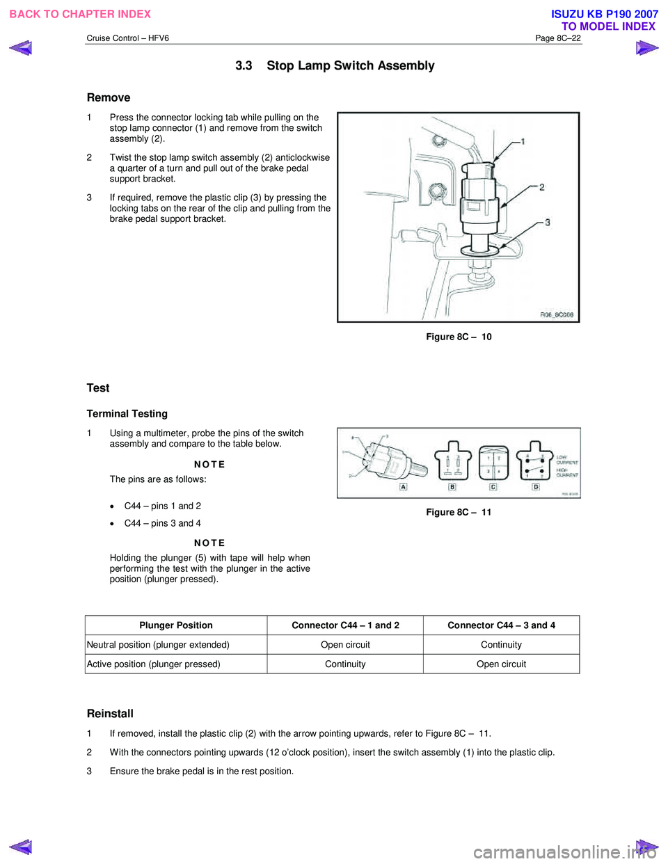
1 Press the connector locking tab while pulling on the
stop lamp connector (1) and remove from the switch
assembly (2).
2 Twist the stop lamp switch assembly (2) anticlockwise a quarter of a turn and pull out of the brake pedal
support bracket.
3 If required, remove the plastic clip (3) by pressing the locking tabs on the rear of the clip and pulling from the
brake pedal support bracket.
Figure 8C – 10
Test
Terminal Testing
1 Using a multimeter, probe the pins of the switch assembly and compare to the table below.
NOTE
The pins are as follows:
• C44 – pins 1 and 2
• C44 – pins 3 and 4
NOTE
Holding the plunger (5) with tape will help when
performing the test with the plunger in the active
position (plunger pressed).
Figure 8C – 11
Plunger Position Connector C44 – 1 and 2 Connector C44 – 3 and 4
Neutral position (plunger extended) Open circuit Continuity
Active position (plunger pressed) Continuity Open circuit
Reinstall
1 If removed, install the plastic clip (2) with the arrow pointing upwards, refer to Figure 8C – 11.
2 With the connectors pointing upwards (12 o’clock position), insert the switch assembly (1) into the plastic clip.
3 Ensure the brake pedal is in the rest position.
BACK TO CHAPTER INDEX TO MODEL INDEXISUZU KB P190 2007
Page 5601 of 6020
Cruise Control – HFV6 Page 8C–23
4 Push the switch assembly (1) so the plunger is
pressed and the end switch barrel is against the brake
pedal (2).
5 Twist the switch assembly clockwise to lock into place. The distance between the brake pedal and the switch
barrel should be 0.7 ± 0.5 mm.
6 Install the wiring connector to the switch assembly.
Figure 8C – 12
BACK TO CHAPTER INDEX TO MODEL INDEXISUZU KB P190 2007
Page 5787 of 6020
CAB 10-29
Important Operations
1. Front Console Assembly • Refer to Floor Consol in this section.
RTW 6A0SH000101
2. Glove Box
• Remove 2 fixing screws and pull on the handle.
RTW 6A0SH000201
3. Instrument Panel Driver Lower Cover Assembly
1) Remove the engine hood opener 2 fixing screws.
2) Remove the lower cover one fixing screw.
3) Pull out the cover (Stick type parking brake only).
4) Pull out the lower cover assembly.
4. Driver Knee Bolster Assembly
• Remove 4 fixing bolts.
Caution:
For precautions on installation or removal of the SRS-air
bag system, refer to section 9 “Supplemental Restraint
System (SRS) - AIR BAG”
5. Driver Air Bag
6. Steering Wheel/Steering Cowl • Refer to Section 3B “STEERING COLUMN” for steering
lock assembly removal steps.
7. Meter Cluster Assembly
• Pull out the 4 clip positions.
BACK TO CHAPTER INDEX TO MODEL INDEX
ISUZU KB P190 2007
Page 5788 of 6020
10-30 CAB
RUW 5A0SH002701
12. Instrument Panel Assembly & Cross Beam
1) Remove the two bolts fixing the steering column to the cross beam and the two bolts fixing the brake pedal
bracket to the cross beam.
2) Remove the two bolts fixing the parking brake bracket to
the cross beam (Stick type parking brake only).
3) Disconnect the control cables at the blower unit and vent
unit.
4) Remove the fasteners fixing the instrument panel and cross beam assembly and the body panel.
5) Disconnect the instrument harness connectors.
This illustration is based on RHD model
RTW 7A0SF000201
BACK TO CHAPTER INDEX TO MODEL INDEX
ISUZU KB P190 2007
Page 5792 of 6020
10-34 CAB
Important Operations
17. Instrument Panel Assembly & Cross Beam 1) Tighten the 4 bolts fixing the cross beam and body panel to the specified torque.
Torque N ⋅m (kgf ⋅m/lb ⋅ft)
19 (1.9/14)
RUW 5A0SH002801
2) A Bolt: Steering Column to Cross Beam
Torque N ⋅m (kgf ⋅m/lb ⋅ft)
20 (2.0/14)
B Bolt: Pedal Bracket to Cross Beam
Torque N ⋅m (kgf ⋅m/lb ⋅ft)
15 (1.5/11)
3) C Bolt: Parking Brake Bracket to Cross Beam
Torque N ⋅m (kgf ⋅m/lb ⋅ft)
15 (1.5/11)
23. Steering Wheel/Steering Cowl • Tighten the steering wheel fixing nut to the specified
torque.
Torque N ⋅m (kgf ⋅m/lb ⋅ft)
34 (3.5/25)
BACK TO CHAPTER INDEX TO MODEL INDEX
ISUZU KB P190 2007