2007 ISUZU KB P190 brake
[x] Cancel search: brakePage 3978 of 6020
7A2-12 TRANSMISSION CONTROL SYSTEM (AW30–40LE)
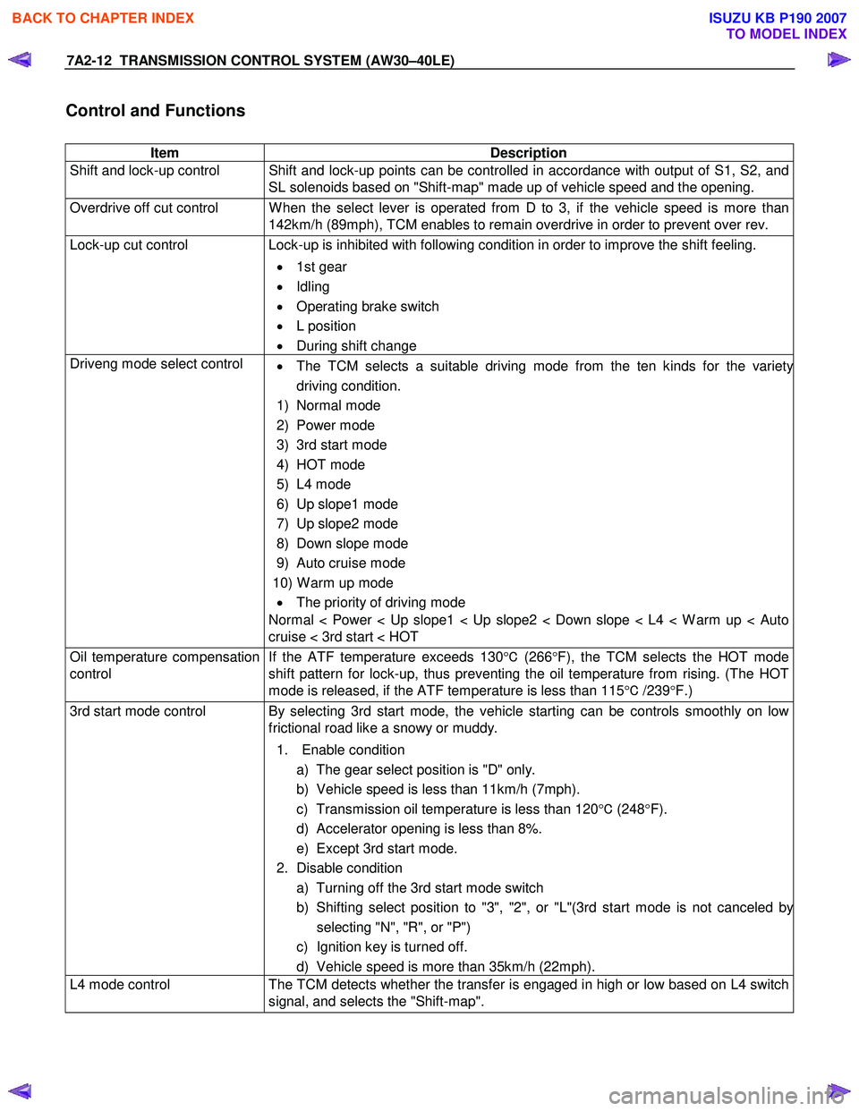
Control and Functions
Item Description
Shift and lock-up control Shift and lock-up points can be controlled in accordance with output of S1, S2, and SL solenoids based on "Shift-map" made up of vehicle speed and the opening.
Overdrive off cut control W hen the select lever is operated from D to 3, if the vehicle speed is more than 142km/h (89mph), TCM enables to remain overdrive in order to prevent over rev.
Lock-up cut control Lock-up is inhibited with following condition in order to improve the shift feeling.
• 1st gear
• Idling
• Operating brake switch
• L position
• During shift change
Driveng mode select control
• The TCM selects a suitable driving mode from the ten kinds for the variety
driving condition.
1) Normal mode
2) Power mode
3) 3rd start mode
4) HOT mode
5) L4 mode
6) Up slope1 mode
7) Up slope2 mode
8) Down slope mode
9) Auto cruise mode
10) W arm up mode • The priority of driving mode
Normal < Power < Up slope1 < Up slope2 < Down slope < L4 < W arm up < Auto
cruise < 3rd start < HOT
Oil temperature compensation
control If the ATF temperature exceeds 130
°C (266 °F), the TCM selects the HOT mode
shift pattern for lock-up, thus preventing the oil temperature from rising. (The HOT
mode is released, if the ATF temperature is less than 115 °C /239 °F.)
3rd start mode control By selecting 3rd start mode, the vehicle starting can be controls smoothly on low
frictional road like a snowy or muddy.
1. Enable condition a) The gear select position is "D" only.
b) Vehicle speed is less than 11km/h (7mph).
c) Transmission oil temperature is less than 120 °C (248 °F).
d) Accelerator opening is less than 8%.
e) Except 3rd start mode.
2. Disable condition a) Turning off the 3rd start mode switch
b) Shifting select position to "3", "2", or "L"(3rd start mode is not canceled b
y
selecting "N", "R", or "P")
c) Ignition key is turned off.
d) Vehicle speed is more than 35km/h (22mph).
L4 mode control The TCM detects whether the transfer is engaged in high or low based on L4 switch
signal, and selects the "Shift-map".
BACK TO CHAPTER INDEX
TO MODEL INDEX
ISUZU KB P190 2007
Page 3979 of 6020
TRANSMISSION CONTROL SYSTEM (AW30–40LE) 7A2-13
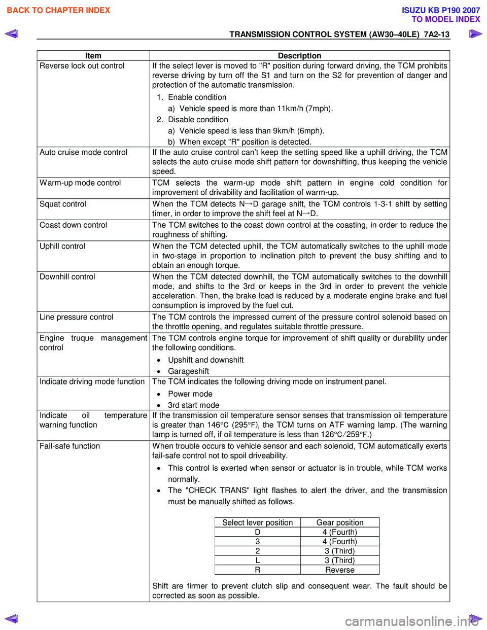
Item Description
Reverse lock out control If the select lever is moved to "R" position during forward driving, the TCM prohibits
reverse driving by turn off the S1 and turn on the S2 for prevention of danger and
protection of the automatic transmission.
1. Enable condition a) Vehicle speed is more than 11km/h (7mph).
2. Disable condition a) Vehicle speed is less than 9km/h (6mph).
b) W hen except "R" position is detected.
Auto cruise mode control If the auto cruise control can’t keep the setting speed like a uphill driving, the TCM selects the auto cruise mode shift pattern for downshifting, thus keeping the vehicle
speed.
W arm-up mode control TCM selects the warm-up mode shift pattern in engine cold condition for improvement of drivability and facilitation of warm-up.
Squat control W hen the TCM detects N→D garage shift, the TCM controls 1-3-1 shift by setting
timer, in order to improve the shift feel at N →D.
Coast down control The TCM switches to the coast down control at the coasting, in order to reduce the
roughness of shifting.
Uphill control W hen the TCM detected uphill, the TCM automatically switches to the uphill mode
in two-stage in proportion to inclination pitch to prevent the busy shifting and to
obtain an enough torque.
Downhill control W hen the TCM detected downhill, the TCM automatically switches to the downhill
mode, and shifts to the 3rd or keeps in the 3rd in order to prevent the vehicle
acceleration. Then, the brake load is reduced by a moderate engine brake and fuel
consumption is improved by the fuel cut.
Line pressure control The TCM controls the impressed current of the pressure control solenoid based on the throttle opening, and regulates suitable throttle pressure.
Engine truque management
control The TCM controls engine torque for improvement of shift quality or durability under
the following conditions.
• Upshift and downshift
• Garageshift
Indicate driving mode function The TCM indicates the following driving mode on instrument panel.
• Power mode
• 3rd start mode
Indicate oil temperature
warning function If the transmission oil temperature sensor senses that transmission oil temperature
is greater than 146 °C (295 °F) , the TCM turns on ATF warning lamp. (The warning
lamp is turned off, if oil temperature is less than 126 °C/ 259 °F .)
Fail-safe function W hen trouble occurs to vehicle sensor and each solenoid, TCM automatically exerts
fail-safe control not to spoil driveability.
• This control is exerted when sensor or actuator is in trouble, while TCM works
normally.
• The "CHECK TRANS" light flashes to alert the driver, and the transmission
must be manually shifted as follows.
Select lever position Gear position
D 4 (Fourth)
3 4 (Fourth)
2 3 (Third)
L 3 (Third)
R Reverse
Shift are firmer to prevent clutch slip and consequent wear. The fault should be
corrected as soon as possible.
BACK TO CHAPTER INDEX
TO MODEL INDEX
ISUZU KB P190 2007
Page 3990 of 6020
7A2-24 TRANSMISSION CONTROL SYSTEM (AW30–40LE)
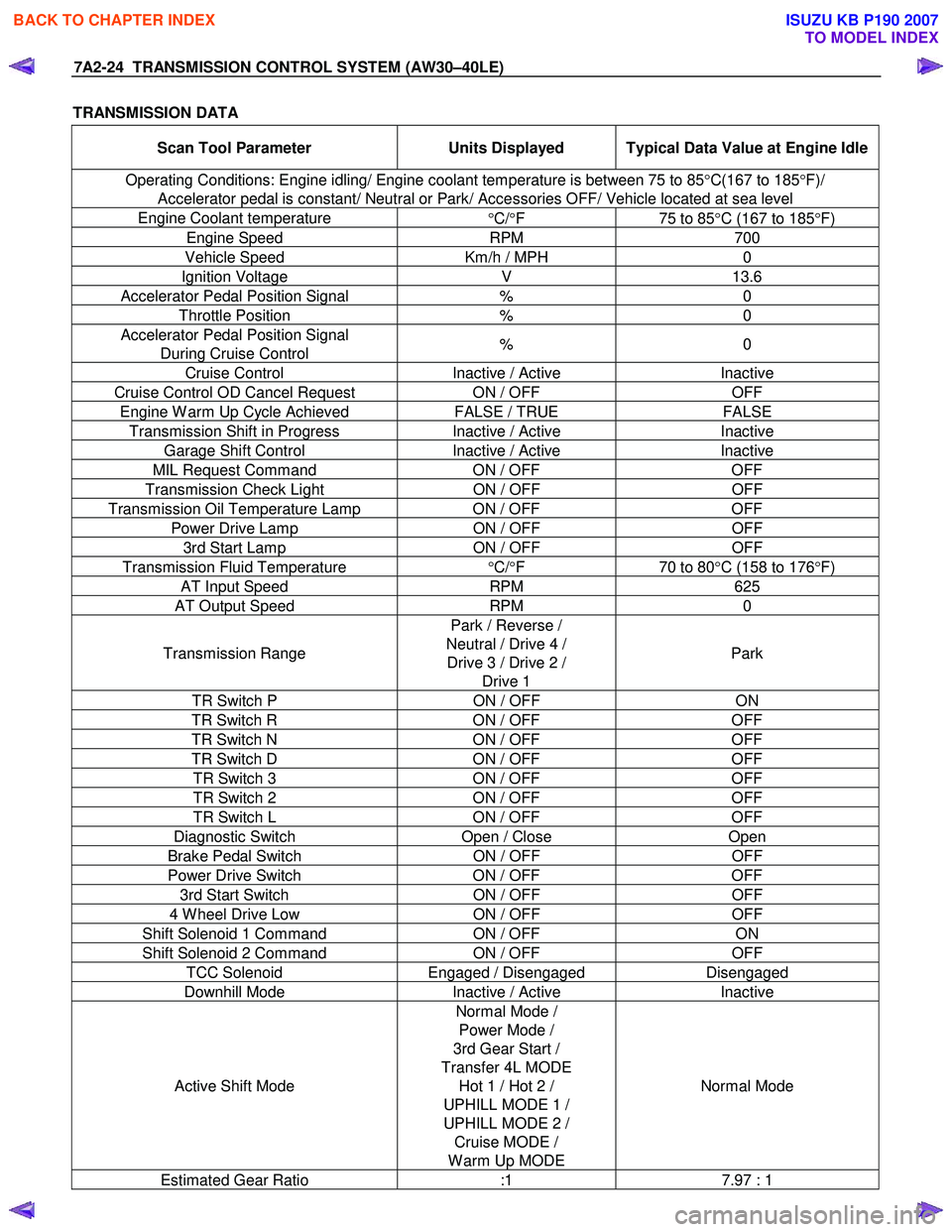
TRANSMISSION DATA
Scan Tool Parameter Units Displayed Typical Data Value at Engine Idle
Operating Conditions: Engine idling/ Engine coolant temperature is between 75 to 85 °C(167 to 185 °F)/
Accelerator pedal is constant/ Neutral or Park/ Accessories OFF/ Vehicle located at sea level
Engine Coolant temperature °C/ °F 75 to 85°C (167 to 185 °F)
Engine Speed RPM 700
Vehicle Speed Km/h / MPH 0
Ignition Voltage V 13.6
Accelerator Pedal Position Signal % 0
Throttle Position % 0
Accelerator Pedal Position Signal
During Cruise Control % 0
Cruise Control
Inactive / Active Inactive
Cruise Control OD Cancel Request ON / OFF OFF
Engine W arm Up Cycle Achieved FALSE / TRUE FALSE
Transmission Shift in Progress Inactive / Active Inactive
Garage Shift Control Inactive / Active Inactive
MIL Request Command ON / OFF OFF
Transmission Check Light ON / OFF OFF
Transmission Oil Temperature Lamp ON / OFF OFF
Power Drive Lamp ON / OFF OFF
3rd Start Lamp ON / OFF OFF
Transmission Fluid Temperature
°C/ °F 70 to 80°C (158 to 176 °F)
AT Input Speed RPM 625
AT Output Speed RPM 0
Transmission Range Park / Reverse /
Neutral / Drive 4 / Drive 3 / Drive 2 / Drive 1 Park
TR Switch P
ON / OFF ON
TR Switch R ON / OFF OFF
TR Switch N ON / OFF OFF
TR Switch D ON / OFF OFF
TR Switch 3 ON / OFF OFF
TR Switch 2 ON / OFF OFF
TR Switch L ON / OFF OFF
Diagnostic Switch Open / Close Open
Brake Pedal Switch ON / OFF OFF
Power Drive Switch ON / OFF OFF
3rd Start Switch ON / OFF OFF
4 W heel Drive Low ON / OFF OFF
Shift Solenoid 1 Command ON / OFF ON
Shift Solenoid 2 Command ON / OFF OFF
TCC Solenoid Engaged / Disengaged Disengaged
Downhill Mode Inactive / Active Inactive
Active Shift Mode Normal Mode /
Power Mode /
3rd Gear Start /
Transfer 4L MODE Hot 1 / Hot 2 /
UPHILL MODE 1 /
UPHILL MODE 2 / Cruise MODE /
W arm Up MODE Normal Mode
Estimated Gear Ratio
:1 7.97 : 1
BACK TO CHAPTER INDEX
TO MODEL INDEX
ISUZU KB P190 2007
Page 4060 of 6020
7A2-94 TRANSMISSION CONTROL SYSTEM (AW30–40LE)
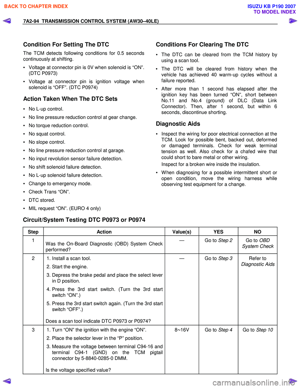
Condition For Setting The DTC
The TCM detects following conditions for 0.5 seconds
continuously at shifting.
• Voltage at connector pin is 0V when solenoid is “ON”.
(DTC P0973)
• Voltage at connector pin is ignition voltage when
solenoid is “OFF”. (DTC P0974)
Action Taken When The DTC Sets
• No L-up control.
• No line pressure reduction control at gear change.
• No torque reduction control.
• No squat control.
• No slope control.
• No line pressure reduction control at garage.
• No input revolution sensor failure detection.
• No shift solenoid failure detection.
• No L-up solenoid failure detection.
• Change to emergency mode.
• Check Trans “ON”.
• DTC stored.
• MIL request “ON”. (EURO 4 only)
Conditions For Clearing The DTC
•
The DTC can be cleared from the TCM history by
using a scan tool.
• The DTC will be cleared from history when the
vehicle has achieved 40 warm-up cycles without a
failure reported.
•
After more than 1 second has elapsed after the
ignition key has been turned “ON”, short between
No.11 and No.4 (ground) of DLC (Data Link
Connector). Then, after 1 second, but within 6
seconds, discontinue shorting.
Diagnostic Aids
• Inspect the wiring for poor electrical connection at the
TCM. Look for possible bent, backed out, deformed
or damaged terminals. Check for weak terminal
tension as well. Also check for a chafed wire that
could short to bare metal or other wiring.
Inspect for a broken wire inside the insulation.
• W hen diagnosing for a possible intermittent short o
r
open condition, move the wiring harness while
observing test equipment for a change.
Circuit/System Testing DTC P0973 or P0974
Step Action Value(s) YES NO
1
W as the On-Board Diagnostic (OBD) System Check
performed? — Go to
Step 2 Go to OBD
System Check
2 1. Install a scan tool.
2. Start the engine.
3. Depress the brake pedal and place the select lever in D position.
4. Press the 3rd start switch. (Turn the 3rd start switch “ON”.)
5. Press the 3rd start switch again. (Turn the 3rd start switch “OFF”.)
Does a scan tool indicate DTC P0973 or P0974? — Go to
Step 3 Refer to
Diagnostic Aids
3 1. Turn “ON” the ignition with the engine “ON”.
2. Place the selector lever in the “P” position.
3. Measure the voltage between terminal C94-16 and terminal C94-1 (GND) on the TCM pigtail
connector by 5-8840-0285-0 DMM.
Is the voltage specified value? 8∼16V Go to
Step 4 Go to Step 10
BACK TO CHAPTER INDEX
TO MODEL INDEX
ISUZU KB P190 2007
Page 4064 of 6020
7A2-98 TRANSMISSION CONTROL SYSTEM (AW30–40LE)
Condition For Setting The DTC
The TCM detects following conditions for 0.5 seconds
continuously at shifting.
• Voltage at connector pin is 0V when solenoid is “ON”.
(DTC P0976)
• Voltage at connector pin is ignition voltage when
solenoid is “OFF”. (DTC P0977)
Action Taken When The DTC Sets
• No L-up control.
• No line pressure reduction control at gear change.
• No torque reduction control.
• No squat control.
• No slope control (keep mode).
• No line pressure reduction control at garage.
• No input revolution sensor failure detection.
• No shift solenoid failure detection.
• No L-up solenoid failure detection.
• Change to emergency mode.
• Check Trans “ON”.
• DTC stored.
• MIL request “ON”. (EURO 4 only)
Conditions For Clearing The DTC
•
The DTC can be cleared from the TCM history by
using a scan tool.
• The DTC will be cleared from history when the vehicle has achieved 40 warm-up cycles without a
failure reported.
•
After more than 1 second has elapsed after the
ignition key has been turned “ON”, short between
No.11 and No.4 (ground) of DLC (Data Link
Connector). Then, after 1 second, but within 6
seconds, discontinue shorting.
Diagnostic Aids
• Inspect the wiring for poor electrical connection at the
TCM. Look for possible bent, backed out, deformed
or damaged terminals. Check for weak terminal
tension as well. Also check for a chafed wire that
could short to bare metal or other wiring.
Inspect for a broken wire inside the insulation.
• W hen diagnosing for a possible intermittent short o
r
open condition, move the wiring harness while
observing test equipment for a change.
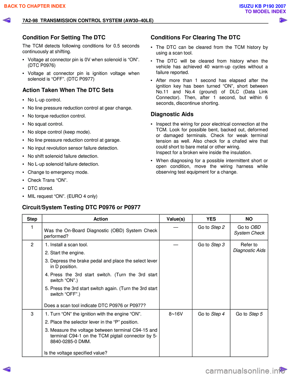
Circuit/System Testing DTC P0976 or P0977
Step Action Value(s) YES NO
1
W as the On-Board Diagnostic (OBD) System Check
performed? — Go to
Step 2 Go to OBD
System Check
2 1. Install a scan tool.
2. Start the engine.
3. Depress the brake pedal and place the select lever in D position.
4. Press the 3rd start switch. (Turn the 3rd start switch “ON”.)
5. Press the 3rd start switch again. (Turn the 3rd start switch “OFF”.)
Does a scan tool indicate DTC P0976 or P0977? — Go to
Step 3 Refer to
Diagnostic Aids
3 1. Turn “ON” the ignition with the engine “ON”.
2. Place the selector lever in the “P” position.
3. Measure the voltage between terminal C94-15 and terminal C94-1 on the TCM pigtail connector by 5-
8840-0285-0 DMM.
Is the voltage specified value? 8∼16V Go to
Step 4 Go to Step 5
BACK TO CHAPTER INDEX
TO MODEL INDEX
ISUZU KB P190 2007
Page 4086 of 6020
ON-VEHICLE SERVICE (AW30–40LE) 7A3-1
SECTION 7A3
ON-VEHICLE SERVICE (AW30–40LE)
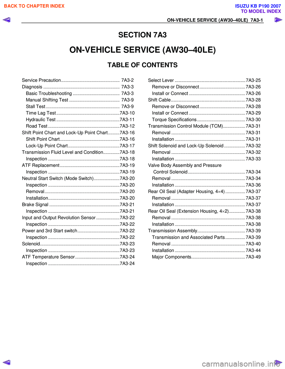
TABLE OF CONTENTS
Service Precaution .................................................. 7A3-2
Diagnosis ................................................................. 7A3-3
Basic Troubleshooting ........................................ 7A3-3
Manual Shifting Test ........................................... 7A3-9
Stall Test ............................................................... 7A3-9
Time Lag Test ...................................................... 7A3-10
Hydraulic Test ...................................................... 7A3-11
Road Test ............................................................. 7A3-12
Shift Point Chart and Lock-Up Point Chart ..........7A3-16
Shift Point Chart ................................................... 7A3-16
Lock-Up Point Chart ............................................ 7A3-17
Transmission Fluid Level and Condition ..............7A3-18
Inspection ............................................................. 7A3-18
ATF Replacement ................................................... 7A3-19
Inspection ............................................................. 7A3-19
Neutral Start Switch (Mode Switch) ......................7A3-20
Inspection ............................................................. 7A3-20
Removal ................................................................ 7A3-20
Installation ............................................................. 7A3-20
Brake Signal ............................................................ 7A3-21
Inspection ............................................................. 7A3-21
Input and Output Revolution Sensor ....................7A3-22
Inspection ............................................................. 7A3-22
Power and 3rd Start switch ....................................7A3-22
Inspection ............................................................. 7A3-22
Solenoid .................................................................... 7A3-23
Inspection ............................................................. 7A3-23
ATF Temperature Sensor ......................................7A3-24
Inspection ............................................................. 7A3-24
Select Lever ....................................................... 7A3-25 Remove or Disconnect .......................................7A3-26
Install or Connect ................................................ 7A3-26
Shift Cable .......................................................... 7A3-28 Remove or Disconnect .......................................7A3-28
Install or Connect ................................................ 7A3-29
Torque Specifications ......................................... 7A3-30
Transmission Control Module (TCM) ...................7A3-31
Removal ............................................................... 7A3-31
Installation ............................................................ 7A3-31
Shift Solenoid and Lock-Up Solenoid ..................7A3-32
Removal ............................................................... 7A3-32
Installation ............................................................ 7A3-33
Valve Body Assembly and Pressure Control Solenoid ................................................. 7A3-34
Removal ............................................................... 7A3-34
Installation ............................................................ 7A3-36
Rear Oil Seal (Adapter Housing, 4 ×4) ................. 7A3-37
Removal ............................................................... 7A3-37
Installation ............................................................ 7A3-37
Rear Oil Seal (Extension Housing, 4 ×2) .............. 7A3-38
Removal ............................................................... 7A3-38
Installation ............................................................ 7A3-38
Transmission Assembly .........................................7A3-39
Transmission and Associated Parts .................7A3-39
Removal ............................................................... 7A3-40
Installation ............................................................ 7A3-44
Major Components .............................................. 7A3-49
BACK TO CHAPTER INDEX
TO MODEL INDEX
ISUZU KB P190 2007
Page 4095 of 6020
7A3-10 ON-VEHICLE SERVICE (AW30–40LE)
Measure Stall Speed
1. Chock the four wheels.
2. Mount an engine tachometer.
3. Fully apply the parking brake.
4. Step down strongly on the brake pedal with your left foot. (Keep the state until the test is completed)
5. Start the engine.
6. Turn off the A/C.
7. Select into the “D" position. Step all the way down on the accelerator pedal with your right foot. Quickl
y
record the highest speed as soon as the engine
speed gets stabilized.
8. Select into the “N” position and maintain the engine
idling condition more than 1 minute.
Stall speed: 2300 ±
±±
±
200 rpm *
* Ambient temperature to be between roughly 10 °C
(50 °F) and 40 °C (104 °F).
Evaluation
1. If the engine speed is the same for both positions
but lower than the specified value:
• Engine output is insufficient.
• Stator one-way clutch is not operating properly.
NOTE: If more than 600 rpm below the specified value,
the torque converter could be faulty.
2. If the stall speed in “D" position is higher than
specified:
• Line pressure too low
• Forward clutch slipping
• No.2 one-way clutch not operating properly
3. If the stall speed in “R" position is higher than
specified:
• Line pressure too low
• Direct clutch slipping
• No.3 brake slipping
4. If the stall speed in the “R" and “D" positions are
higher than specified:
• Line pressure too low
• Improper fluid level
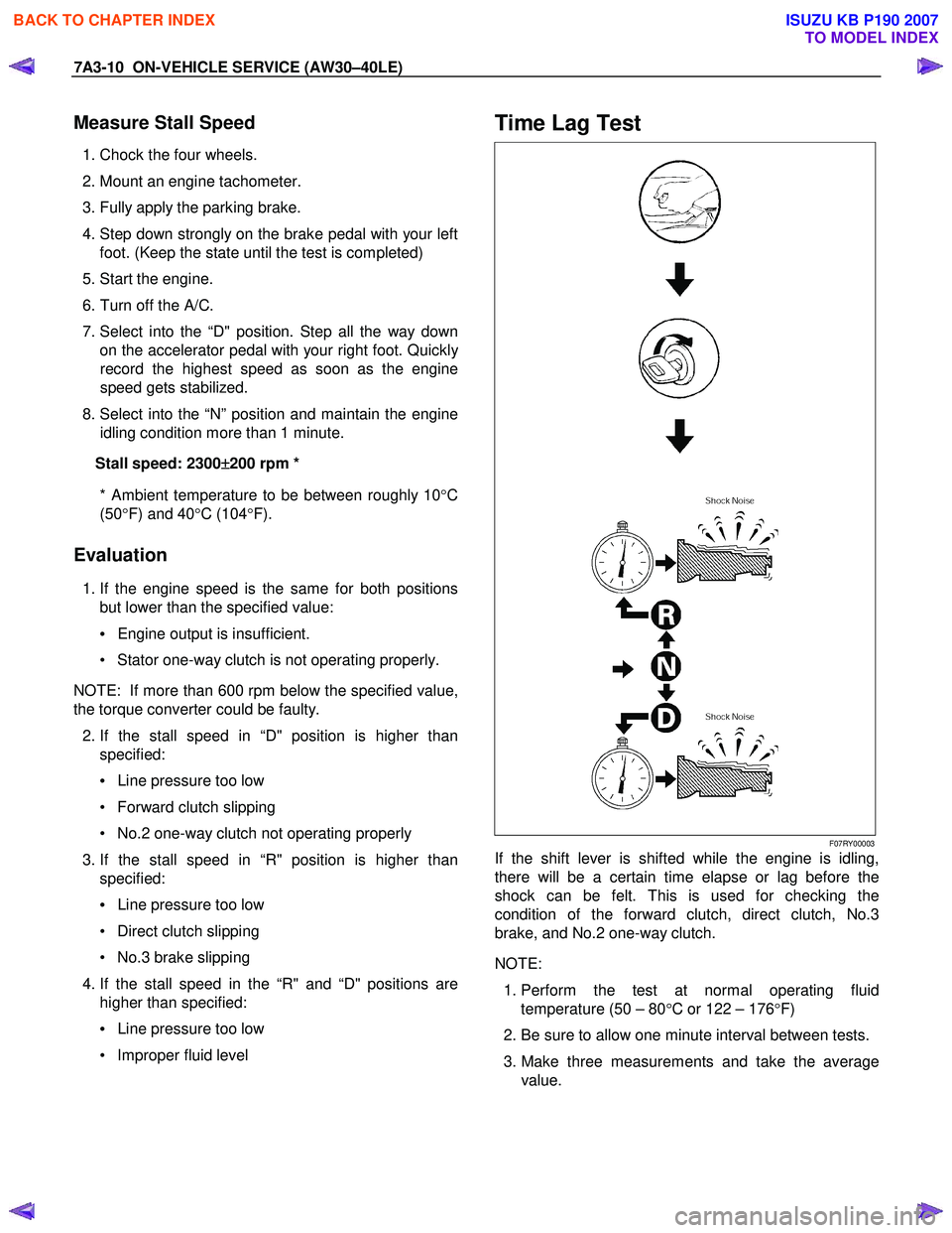
Time Lag Test
F07RY00003
If the shift lever is shifted while the engine is idling,
there will be a certain time elapse or lag before the
shock can be felt. This is used for checking the
condition of the forward clutch, direct clutch, No.3
brake, and No.2 one-way clutch.
NOTE:
1. Perform the test at normal operating fluid
temperature (50 – 80 °C or 122 – 176 °F)
2. Be sure to allow one minute interval between tests.
3. Make three measurements and take the average value.
BACK TO CHAPTER INDEX
TO MODEL INDEX
ISUZU KB P190 2007
Page 4096 of 6020
ON-VEHICLE SERVICE (AW30–40LE) 7A3-11
Measure Time Lag
1. Fully apply the parking brake.
2. Start the engine. Check idling speed (A/C OFF).
3. Operate the select lever from “N" to “D" position.
Using a stopwatch, measure the time it takes from
shifting the lever until the shock is felt.
Time lag: Less than 0.7 seconds
4. In same manner, measure the time lag for “N" →
“R".
Time lag: Less than 1.2 seconds
Evaluation
1. If “N" → “D" time lag is longer than specified:
• Line pressure too low
• Forward clutch malfunction
• No.2 one-way clutch not operating properly
2. If “N" → “R" time lag is longer than specified:
• Line pressure too low
• Direct clutch malfunction
• First and Reverse brake malfunction
3. If both time lag is longer than specified:
• Line pressure too low
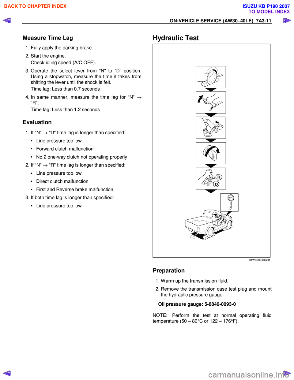
Hydraulic Test
RTW 67ALH000201
Preparation
1. W arm up the transmission fluid.
2. Remove the transmission case test plug and mount the hydraulic pressure gauge.
Oil pressure gauge: 5-8840-0093-0
NOTE: Perform the test at normal operating fluid
temperature (50 – 80 °C or 122 – 176 °F).
BACK TO CHAPTER INDEX
TO MODEL INDEX
ISUZU KB P190 2007