2007 ISUZU KB P190 brake
[x] Cancel search: brakePage 3843 of 6020
Automatic Transmission – 4L60E – Electrical Diagnosis Page 7C2–57
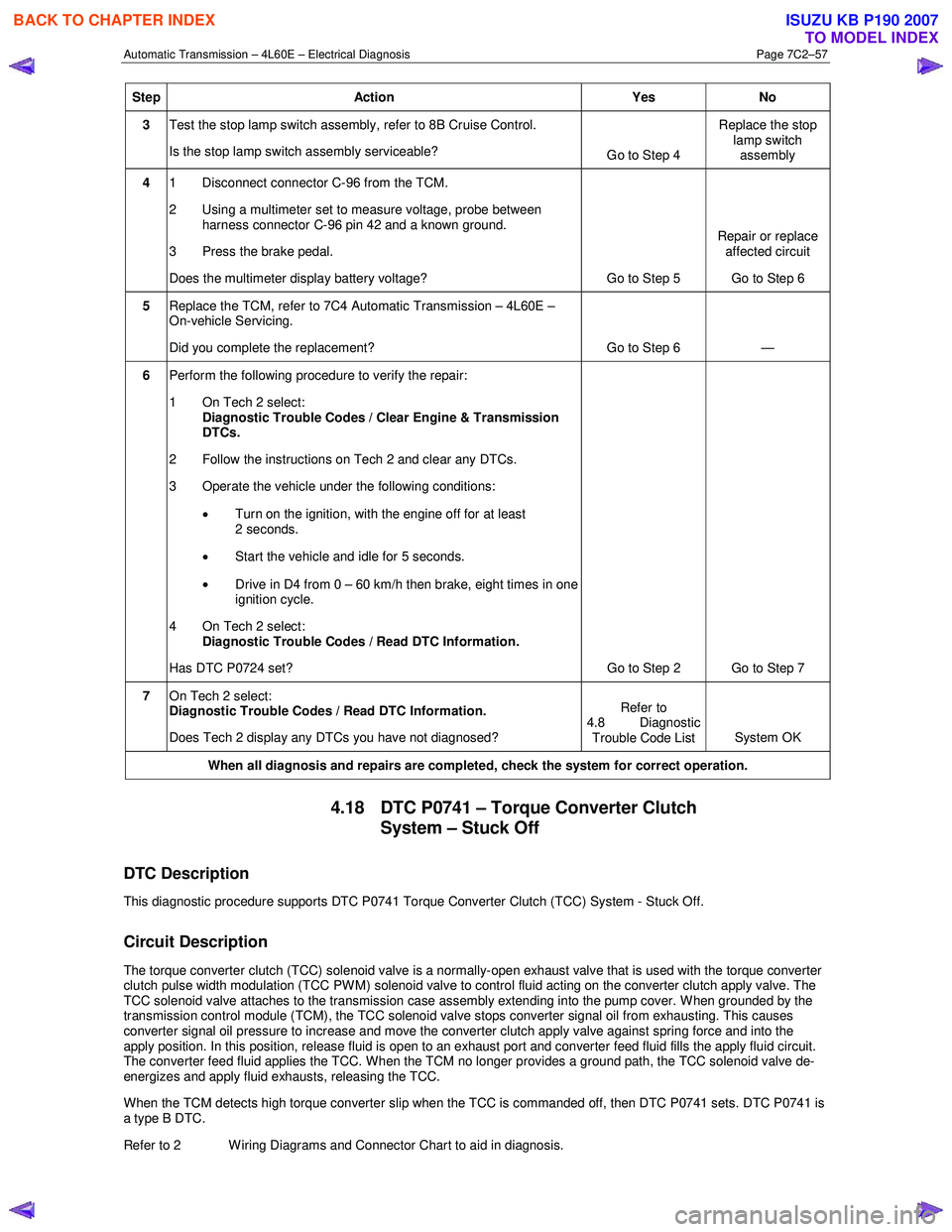
Step Action Yes No
3 Test the stop lamp switch assembly, refer to 8B Cruise Control.
Is the stop lamp switch assembly serviceable? Go to Step 4 Replace the stop
lamp switch assembly
4 1 Disconnect connector C-96 from the TCM.
2 Using a multimeter set to measure voltage, probe between harness connector C-96 pin 42 and a known ground.
3 Press the brake pedal.
Does the multimeter display battery voltage? Go to Step 5 Repair or replace
affected circuit
Go to Step 6
5 Replace the TCM, refer to 7C4 Automatic Transmission – 4L60E –
On-vehicle Servicing.
Did you complete the replacement? Go to Step 6 —
6 Perform the following procedure to verify the repair:
1 On Tech 2 select: Diagnostic Trouble Codes / Clear Engine & Transmission
DTCs.
2 Follow the instructions on Tech 2 and clear any DTCs.
3 Operate the vehicle under the following conditions:
• Turn on the ignition, with the engine off for at least
2 seconds.
• Start the vehicle and idle for 5 seconds.
• Drive in D4 from 0 – 60 km/h then brake, eight times in one
ignition cycle.
4 On Tech 2 select:
Diagnostic Trouble Codes / Read DTC Information.
Has DTC P0724 set? Go to Step 2 Go to Step 7
7 On Tech 2 select:
Diagnostic Trouble Codes / Read DTC Information.
Does Tech 2 display any DTCs you have not diagnosed? Refer to
4.8 Diagnostic Trouble Code List System OK
When all diagnosis and repairs are completed, check the
system for correct operation.
4.18 DTC P0741 – Torque Converter Clutch
System – Stuck Off
DTC Description
This diagnostic procedure supports DTC P0741 Torque Converter Clutch (TCC) System - Stuck Off.
Circuit Description
The torque converter clutch (TCC) solenoid valve is a normally-open exhaust valve that is used with the torque converter
clutch pulse width modulation (TCC PWM) solenoid valve to control fluid acting on the converter clutch apply valve. The
TCC solenoid valve attaches to the transmission case assembly extending into the pump cover. W hen grounded by the
transmission control module (TCM), the TCC solenoid valve stops converter signal oil from exhausting. This causes
converter signal oil pressure to increase and move the converter clutch apply valve against spring force and into the
apply position. In this position, release fluid is open to an exhaust port and converter feed fluid fills the apply fluid circu it.
The converter feed fluid applies the TCC. When the TCM no longer provides a ground path, the TCC solenoid valve de-
energizes and apply fluid exhausts, releasing the TCC.
When the TCM detects high torque converter slip when the TCC is commanded off, then DTC P0741 sets. DTC P0741 is
a type B DTC.
Refer to 2 W iring Diagrams and Connector Chart to aid in diagnosis.
BACK TO CHAPTER INDEX
TO MODEL INDEX
ISUZU KB P190 2007
Page 3847 of 6020
Automatic Transmission – 4L60E – Electrical Diagnosis Page 7C2–61
• The vehicle speed is greater than 15 km/h.
• TCC is commanded off.
Conditions for Setting the DTC
The following conditions occur four times in one ignition cycle:
• The TCM commands the TCC off.
• The TCC slip is -15 – +15 r.p.m. for greater than 3 seconds.
Action Taken When the DTC Sets
•
The TCM requests the ECM to illuminate the MIL during the second consecutive drive trip in which the conditions
for setting the DTC are met.
• The TCM commands maximum line pressure.
• The TCM freezes transmission adaptive functions.
• At the time of the first failure, the TCM records the operating conditions when the conditions for setting the DTC are
met. The TCM stores this information as a Failure Record.
• At the time of the second failure, the ECM records the operating conditions when the conditions for setting the DTC
are met. The ECM stores this information as a Freeze Frame.
• The TCM stores DTC P0742 in TCM history.
Conditions for Clearing the DTC
• The ECM turns off the MIL after the sixth consecutive drive trip in which the TCM does not send a MIL illumination
request.
• Tech 2 can clear the DTC.
• The TCM clears the DTC from TCM history if the vehicle completes 40 warm-up cycles without a non-emission
related diagnostic fault occurring.
• The TCM cancels the default actions when the ignition is off long enough to power down the TCM.
Diagnostic Aids
The TCC fluid hydraulically applies the TCC, possibly causing an engine stall, under the following conditions:
• The TCC is hydraulically stuck in the on position
• The parking brake is applied.
• Any gear range is selected.
• Contamination may cause the TCC apply valve to intermittently stick in the valve body.
• Internal damage in the torque converter may cause no TCC apply.
Test Description
The following numbers refer to the step numbers in the diagnostic table:
2 This step tests the hydraulic state of the TCC. W hen the TCM commands the TCC solenoid valve off, the slip speed should increase.
3 Checks the mechanical components that cause the DTC and their state.
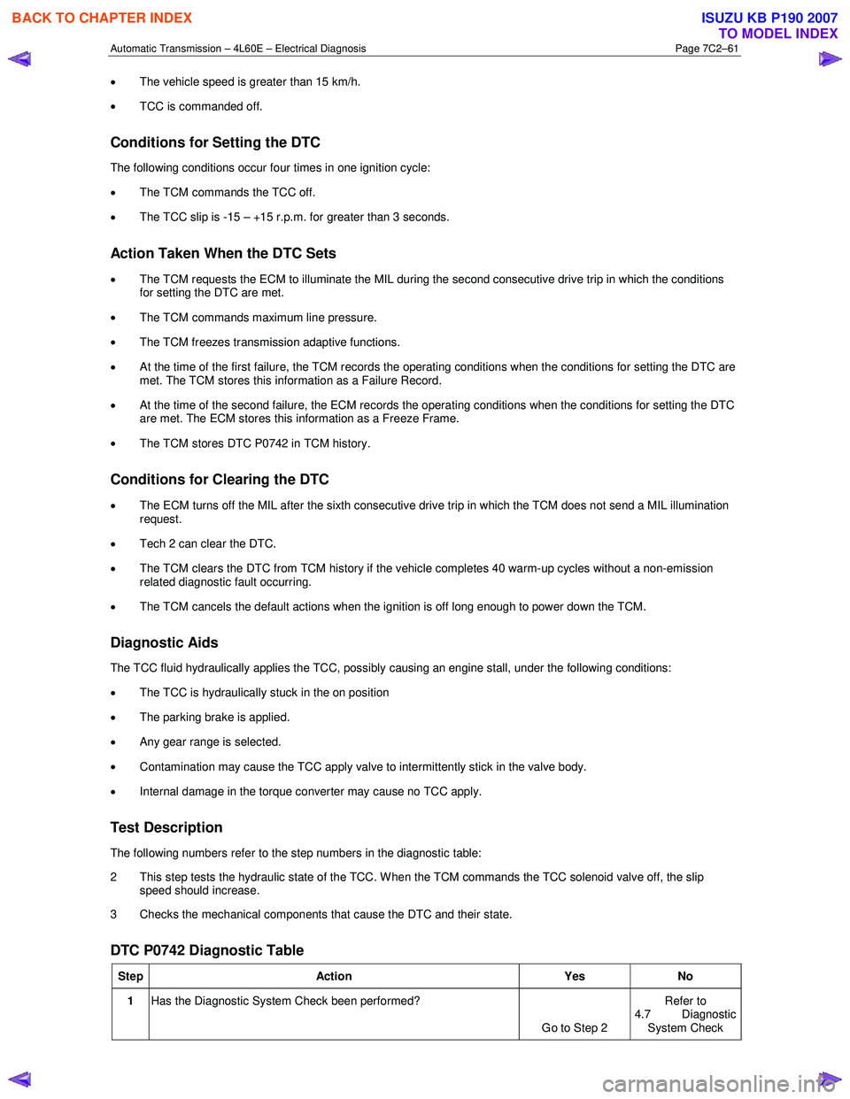
DTC P0742 Diagnostic Table
Step Action Yes No
1 Has the Diagnostic System Check been performed?
Go to Step 2 Refer to
4.7 Diagnostic
System Check
BACK TO CHAPTER INDEX
TO MODEL INDEX
ISUZU KB P190 2007
Page 3892 of 6020
Automatic Transmission – 4L60E – Electrical Diagnosis Page 7C2–106
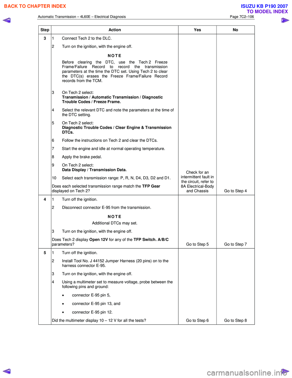
Step Action Yes No
3 1 Connect Tech 2 to the DLC.
2 Turn on the ignition, with the engine off.
NOTE
Before clearing the DTC, use the Tech 2 Freeze
Frame/Failure Record to record the transmission
parameters at the time the DTC set. Using Tech 2 to clear
the DTC(s) erases the Freeze Frame/Failure Record
records from the TCM.
3 On Tech 2 select: Transmission / Automatic Transmission / Diagnostic
Trouble Codes / Freeze Frame.
4 Select the relevant DTC and note the parameters at the time of the DTC setting.
5 On Tech 2 select:
Diagnostic Trouble Codes / Clear Engine & Transmission
DTCs.
6 Follow the instructions on Tech 2 and clear the DTCs.
7 Start the engine and idle at normal operating temperature.
8 Apply the brake pedal.
9 On Tech 2 select: Data Display / Transmission Data.
10 Select each transmission range: P, R, N, D4, D3, D2 and D1.
Does each selected transmission range match the TFP Gear
displayed on Tech 2? Check for an
intermittent fault in
the circuit, refer to
8A Electrical-Body and Chassis Go to Step 4
4 1 Turn off the ignition.
2 Disconnect connector E-95 from the transmission.
NOTE
Additional DTCs may set.
3 Turn on the ignition, with the engine off.
Does Tech 2 display Open 12V for any of the TFP Switch. A/B/C
parameters? Go to Step 5 Go to Step 7
5 1 Turn off the ignition.
2 Install Tool No. J 44152 Jumper Harness (20 pins) on to the harness connector E-95.
3 Turn on the ignition, with the engine off.
4 Using a multimeter set to measure voltage, probe between the following pins and ground:
• connector E-95 pin 5,
• connector E-95 pin 13, and
• connector E-95 pin 12.
Did the multimeter display 10 – 12 V for all the tests? Go to Step 6 Go to Step 8
BACK TO CHAPTER INDEX
TO MODEL INDEX
ISUZU KB P190 2007
Page 3918 of 6020
Automatic Transmission – 4L60E – On-vehicle Servicing Page 7C4–5
2 Maintenance Operations
2.1 Transmission Fluid
When adding or changing the transmission fluid, use only the recommended automatic transmission fluid, refer to
0B Maintenance and Lubrication.
For the automatic transmission fluid diagnosis, refer to 7C3 Automatic Transmission – 4L60E – Hydraulic and
Mechanical Diagnosis.
Transmission Fluid Colour
New transmission fluid is red in colour due to a dye that is added to the fluid so it can be distinguished from other oils and
lubricants. The red dye is not permanent and as such, is not an indicator of the quality of the fluid.
As the vehicle is driven the transmission fluid will quickly look darker in colour and appear to be a light brown. A dark
brown colour with a distinctively burnt odour may indicate fluid deterioration and the need for fluid replacement.
NOTE
A dark brown fluid colour observed, coupled with
a reported delayed shift pattern may only indicate
that fluid replacement is required. This is not a
definite indication of a potential transmission
failure.
Transmission Fluid Level
NOTE
Carry out this operation with the transmission at
normal operating temperature (82 – 94°C), as the
temperature greatly affects the fluid level.
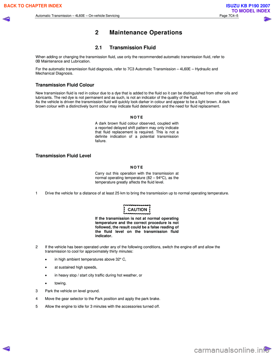
1 Drive the vehicle for a distance of at least 25 km to bring the transmission up to normal operating temperature.
If the transmission is not at normal operating
temperature and the correct procedure is not
followed, the result could be a false reading of
the fluid level on the transmission fluid
indicator.
2 If the vehicle has been operated under any of the following conditions, switch the engine off and allow the transmission to cool for approximately thirty minutes:
• in high ambient temperatures above 32° C,
• at sustained high speeds,
• in heavy stop / start city traffic during hot weather, or
• towing.
3 Park the vehicle on level ground.
4 Move the gear selector to the Park position and apply the park brake.
5 Allow the engine to idle for 3 minutes with the accessories turned off.
BACK TO CHAPTER INDEX
TO MODEL INDEX
ISUZU KB P190 2007
Page 3968 of 6020
7A2-2 TRANSMISSION CONTROL SYSTEM (AW30–40LE)
Service Precaution
WARNING: THIS VEHICLE HAS A SUPPLEMENTAL
RESTRAINT SYSTEM (SRS). REFER TO THE SRS
COMPONENT AND WIRING LOCATION VIEW IN
ORDER TO DETERMINE WHETHER YOU ARE
PERFORMING SERVICE ON OR NEAR THE SRS
COMPONENTS OR THE SRS WIRING. WHEN YOU
ARE PERFORMING SERVICE ON OR NEAR THE
SRS COMPONENTS OR THE SRS WIRING, REFER
TO THE SRS SERVICE INFORMATION. FAILURE TO
FOLLOW WARNINGS COULD RESULT IN
POSSIBLE AIR BAG DEPLOYMENT, PERSONAL
INJURY, OR OTHERWISE UNNEEDED SRS SYSTEM
REPAIRS.
CAUTION: Always use the correct fastener in the
proper location. When you replace a fastener, use
ONLY the exact part number for that application.
ISUZU will call out those fasteners that require a
replacement after removal. ISUZU will also call out
the fasteners that require thread lockers or thread
sealant. UNLESS OTHERWISE SPECIFIED, do not
use supplemental coatings (Paints, greases, o
r
other corrosion inhibitors) on threaded fasteners or
fastener joint interfaces. Generally, such coatings
adversely affect the fastener torque and the joint
clamping force, and may damage the fastener.
When you install fasteners, use the correct
tightening sequence and specifications. Following
these instructions can help you avoid damage to
parts and systems.
General Description
The AW 30-40LE is a 4–speed fully electronically
controlled automatic transmission. It uses a
microcomputer as a control unit to judge driving
conditions including throttle opening rate and vehicle
speed, then it sets the shifting point in the optimum
timing so that best driving performance can be
achieved.
In addition, the built–in driving mode select function can
select three driving modes according to the driver's
preference:
• Normal mode –Normal shift pattern.
• 3rd Start mode –Starts in 3rd gear to reduce slippage
on mud, ice or snow.
• Power mode –Delays upshift timing when more
powerful acceleration is required.
Also, the built–in fail–safe function (“emergency mode")
assures driving performance even if the vehicle speed
sensor, throttle signal or any solenoid fails.
Further, the self–diagnostic function conducts diagnosis
in a short time when the control system fails, thus
improving serviceability.
The major features of AW 30-40LE are as follows:
•
A compact structure consisting of 2 sets of planetary
gears and flat torque converter.
• Electronic control selects the optimum driving mode according to the driving conditions.
• Electronic control maintains the optimum hydraulic
pressure for clutch, band brake as well as
transmission so that shift feeling is improved.
• W ide gear ratio and high torque rate of torque
converter provide excellent starting performance.
• Optimum Lock-up control of each driving mode can
have it both ways driving performance and fuel
economy.
• Excellent shift quality can be achieved by the torque
management control through the CAN
communication with the engine.
BACK TO CHAPTER INDEX
TO MODEL INDEX
ISUZU KB P190 2007
Page 3969 of 6020
TRANSMISSION CONTROL SYSTEM (AW30–40LE) 7A2-3
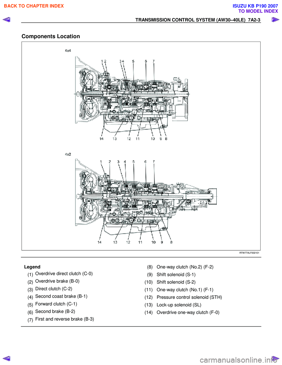
Components Location
RTW 77ALF002101
Legend (8) One-way clutch (No.2) (F-2)
(1) Overdrive direct clutch (C-0)
(9) Shift solenoid (S-1)
(2) Overdrive brake (B-0)
(10) Shift solenoid (S-2)
(3) Direct clutch (C-2)
(11) One-way clutch (No.1) (F-1)
(4) Second coast brake (B-1)
(12) Pressure control solenoid (STH)
(5) Forward clutch (C-1)
(13) Lock-up solenoid (SL)
(6) Second brake (B-2)
(14) Overdrive one-way clutch (F-0)
(7) First and reverse brake (B-3)
BACK TO CHAPTER INDEX
TO MODEL INDEX
ISUZU KB P190 2007
Page 3974 of 6020
7A2-8 TRANSMISSION CONTROL SYSTEM (AW30–40LE)
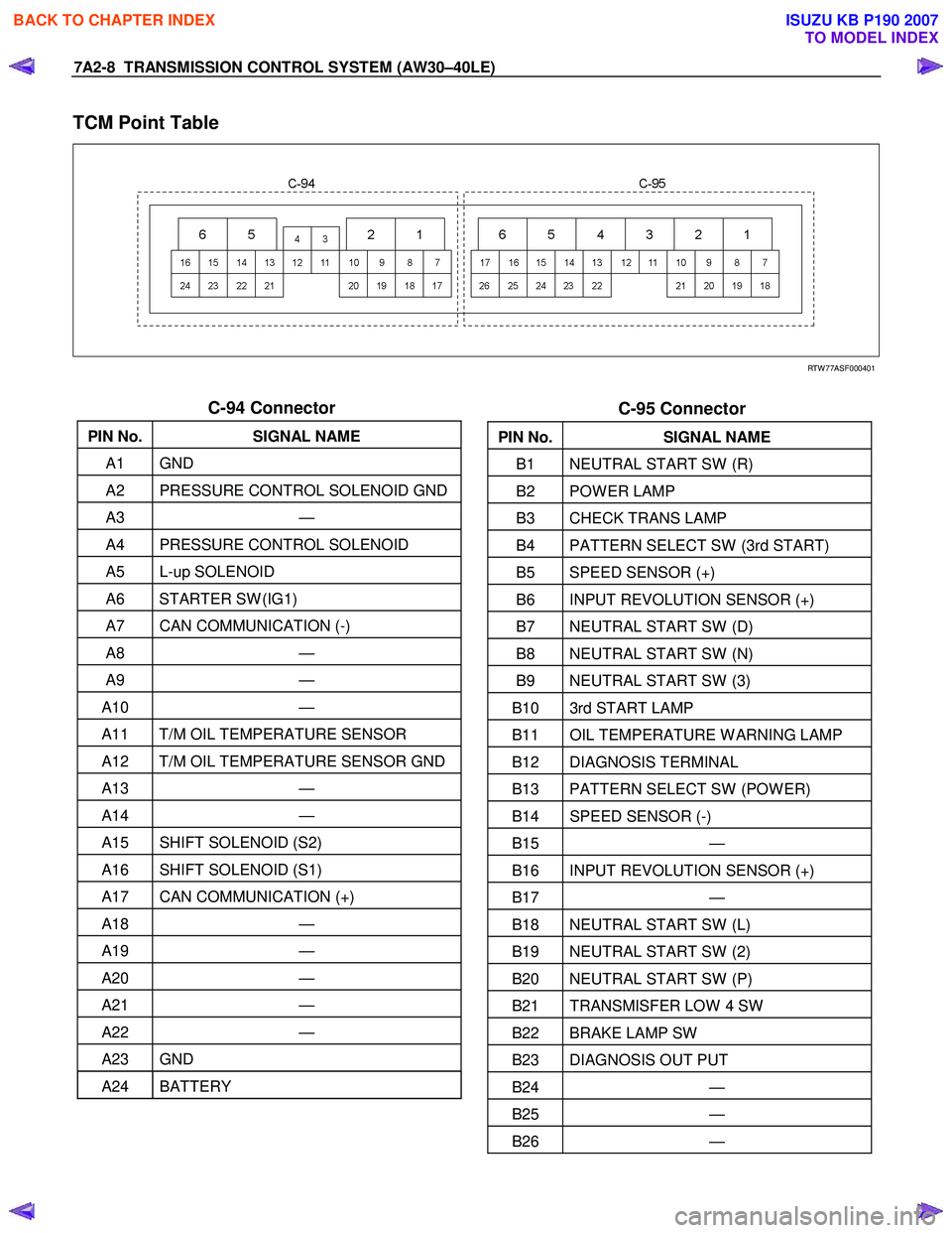
TCM Point Table
RTW 77ASF000401
C-94 Connector
PIN No. SIGNAL NAME
A1 GND
A2 PRESSURE CONTROL SOLENOID GND
A3 —
A4 PRESSURE CONTROL SOLENOID
A5 L-up SOLENOID
A6 STARTER SW (IG1)
A7 CAN COMMUNICATION (-)
A8 —
A9 —
A10 —
A11 T/M OIL TEMPERATURE SENSOR
A12 T/M OIL TEMPERATURE SENSOR GND
A13 —
A14 —
A15 SHIFT SOLENOID (S2)
A16 SHIFT SOLENOID (S1)
A17 CAN COMMUNICATION (+)
A18 —
A19 —
A20 —
A21 —
A22 —
A23 GND
A24 BATTERY
C-95 Connector
PIN No. SIGNAL NAME
B1 NEUTRAL START SW (R)
B2 POW ER LAMP
B3 CHECK TRANS LAMP
B4 PATTERN SELECT SW (3rd START)
B5 SPEED SENSOR (+)
B6 INPUT REVOLUTION SENSOR (+)
B7 NEUTRAL START SW (D)
B8 NEUTRAL START SW (N)
B9 NEUTRAL START SW (3)
B10 3rd START LAMP
B11 OIL TEMPERATURE W ARNING LAMP
B12 DIAGNOSIS TERMINAL
B13 PATTERN SELECT SW (POW ER)
B14 SPEED SENSOR (-)
B15 —
B16 INPUT REVOLUTION SENSOR (+)
B17 —
B18 NEUTRAL START SW (L)
B19 NEUTRAL START SW (2)
B20 NEUTRAL START SW (P)
B21 TRANSMISFER LOW 4 SW
B22 BRAKE LAMP SW
B23 DIAGNOSIS OUT PUT
B24 —
B25 —
B26 —
BACK TO CHAPTER INDEX
TO MODEL INDEX
ISUZU KB P190 2007
Page 3975 of 6020
TRANSMISSION CONTROL SYSTEM (AW30–40LE) 7A2-9
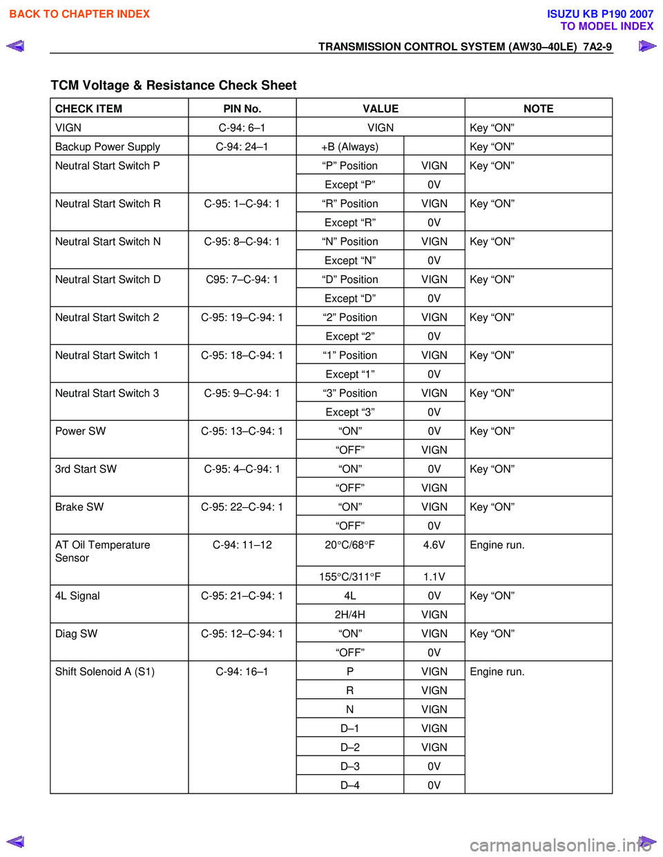
TCM Voltage & Resistance Check Sheet
CHECK ITEM PIN No. VALUE NOTE
VIGN C-94: 6–1 VIGN Key “ON”
Backup Power Supply C-94: 24–1 +B (Always) Key “ON”
Neutral Start Switch P “P” Position VIGN Key “ON”
Except “P” 0V
Neutral Start Switch R C-95: 1–C-94: 1 “R” Position VIGN Key “ON”
Except “R” 0V
Neutral Start Switch N C-95: 8–C-94: 1 “N” Position VIGN Key “ON”
Except “N” 0V
Neutral Start Switch D C95: 7–C-94: 1 “D” Position VIGN Key “ON”
Except “D” 0V
Neutral Start Switch 2 C-95: 19–C-94: 1 “2” Position VIGN Key “ON”
Except “2” 0V
Neutral Start Switch 1 C-95: 18–C-94: 1 “1” Position VIGN Key “ON”
Except “1” 0V
Neutral Start Switch 3 C-95: 9–C-94: 1 “3” Position VIGN Key “ON”
Except “3” 0V
Power SW C-95: 13–C-94: 1 “ON” 0V Key “ON”
“OFF” VIGN
3rd Start SW C-95: 4–C-94: 1 “ON” 0V Key “ON”
“OFF” VIGN
Brake SW C-95: 22–C-94: 1 “ON” VIGN Key “ON”
“OFF” 0V
AT Oil Temperature
Sensor C-94: 11–12 20
°C/68 °F 4.6V Engine run.
155°C/311 °F 1.1V
4L Signal C-95: 21–C-94: 1 4L 0V Key “ON”
2H/4H VIGN
Diag SW C-95: 12–C-94: 1 “ON” VIGN Key “ON”
“OFF” 0V
Shift Solenoid A (S1) C-94: 16–1 P VIGN Engine run.
R VIGN
N VIGN
D–1 VIGN
D–2 VIGN
D–3 0V
D–4 0V
BACK TO CHAPTER INDEX
TO MODEL INDEX
ISUZU KB P190 2007