2007 ISUZU KB P190 brake
[x] Cancel search: brakePage 3383 of 6020
Engine Management – V6 – Diagnostics Page 6C1-2–105
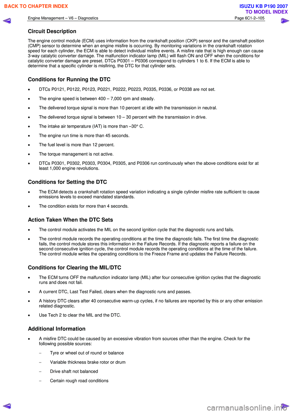
Circuit Description
The engine control module (ECM) uses information from the crankshaft position (CKP) sensor and the camshaft position
(CMP) sensor to determine when an engine misfire is occurring. By monitoring variations in the crankshaft rotation
speed for each cylinder, the ECM is able to detect individual misfire events. A misfire rate that is high enough can cause
3-way catalytic converter damage. The malfunction indicator lamp (MIL) will flash ON and OFF when the conditions for
catalytic converter damage are preset. DTCs P0301 – P0306 correspond to cylinders 1 to 6. If the ECM is able to
determine that a specific cylinder is misfiring, the DTC for that cylinder sets.
Conditions for Running the DTC
• DTCs P0121, P0122, P0123, P0221, P0222, P0223, P0335, P0336, or P0338 are not set.
• The engine speed is between 400 – 7,000 rpm and steady.
• The delivered torque signal is more than 10 percent at idle with the transmission in neutral.
• The delivered torque signal is between 10 – 30 percent with the transmission in drive.
• The intake air temperature (IAT) is more than –30° C.
• The engine run time is more than 45 seconds.
• The fuel level is more than 12 percent.
• The torque management is not active.
• DTCs P0301, P0302, P0303, P0304, P0305, and P0306 run continuously when the above conditions exist for at
least 1,000 engine revolutions.
Conditions for Setting the DTC
• The ECM detects a crankshaft rotation speed variation indicating a single cylinder misfire rate sufficient to cause
emissions levels to exceed mandated standards.
• The condition exists for more than 4 seconds.
Action Taken When the DTC Sets
• The control module activates the MIL on the second ignition cycle that the diagnostic runs and fails.
• The control module records the operating conditions at the time the diagnostic fails. The first time the diagnostic
fails, the control module stores this information in the Failure Records. If the diagnostic reports a failure on the
second consecutive ignition cycle, the control module records the operating conditions at the time of the failure.
The control module writes the operating conditions to the Freeze Frame and updates the Failure Records.
Conditions for Clearing the MIL/DTC
• The ECM turns OFF the malfunction indicator lamp (MIL) after four consecutive ignition cycles that the diagnostic
runs and does not fail.
• A current DTC, Last Test Failed, clears when the diagnostic runs and passes.
• A history DTC clears after 40 consecutive warm-up cycles, if no failures are reported by this or any other emission
related diagnostic.
• Use Tech 2 to clear the MIL and the DTC.
Additional Information
• A misfire DTC could be caused by an excessive vibration from sources other than the engine. Check for the
following possible sources:
− Tyre or wheel out of round or balance
− Variable thickness brake rotor or drum
− Drive shaft not balanced
− Certain rough road conditions
BACK TO CHAPTER INDEX
TO MODEL INDEX
ISUZU KB P190 2007
Page 3411 of 6020
Engine Management – V6 – Diagnostics Page 6C1-2–133
Step Action Yes No
13 Using Tech 2, select the DTC display function.
Are there any DTCs displayed? Go to the
appropriate DTC
Table in this Section System OK
When all diagnosis and repairs are completed, check the system for correct operation.
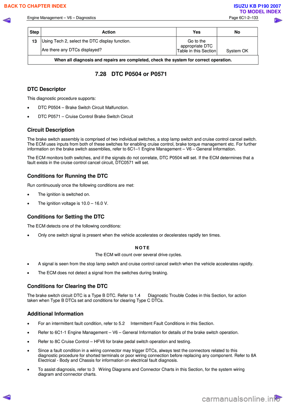
7.28 DTC P0504 or P0571
DTC Descriptor
This diagnostic procedure supports:
• DTC P0504 – Brake Switch Circuit Malfunction.
• DTC P0571 – Cruise Control Brake Switch Circuit
Circuit Description
The brake switch assembly is comprised of two individual switches, a stop lamp switch and cruise control cancel switch.
The ECM uses inputs from both of these switches for enabling cruise control, brake torque management etc. For further
information on the brake switch assemblies, refer to 6C1–1 Engine Management – V6 – General Information.
The ECM monitors both switches, and if the signals do not correlate, DTC P0504 will set. If the ECM determines that a
fault exists in the cruise control cancel circuit, DTC0571 will set.
Conditions for Running the DTC
Run continuously once the following conditions are met:
• The ignition is switched on.
• The ignition voltage is 10.0 – 16.0 V.
Conditions for Setting the DTC
The ECM detects one of the following conditions:
• Only one switch signal is present when the vehicle accelerates or decelerates rapidly ten times.
NOTE
The ECM will count over several drive cycles.
• A signal is seen from the stop lamp switch and cruise control cancel switch when the vehicle accelerates rapidly.
• The ECM does not detect a signal from the switches during braking.
Conditions for Clearing the DTC
The brake switch circuit DTC is a Type B DTC. Refer to 1.4 Diagnostic Trouble Codes in this Section, for action
taken when Type B DTCs set and conditions for clearing Type C DTCs.
Additional Information
• For an intermittent fault condition, refer to 5.2 Intermittent Fault Conditions in this Section.
• Refer to 6C1-1 Engine Management – V6 – General Information for details of the brake switch operation.
• Refer to 8C Cruise Control – HFV6 for brake pedal switch operation and testing.
• Since a fault condition in a wiring connector may trigger DTCs, always test the connectors related to this
diagnostic procedure for shorted terminals or poor wiring connection before replacing any component. Refer to 8A
Electrical - Body and Chassis for information on electrical fault diagnosis.
• To assist diagnosis, refer to 3 W iring Diagrams and Connector Charts in this Section, for the system wiring
diagram and connector charts.
BACK TO CHAPTER INDEX
TO MODEL INDEX
ISUZU KB P190 2007
Page 3412 of 6020
Engine Management – V6 – Diagnostics Page 6C1-2–134
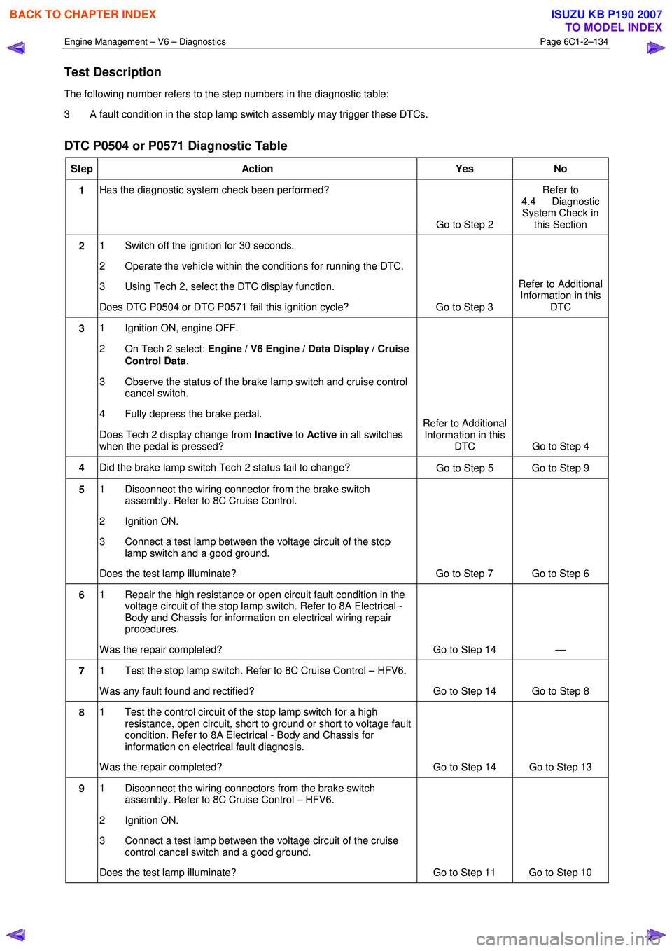
Test Description
The following number refers to the step numbers in the diagnostic table:
3 A fault condition in the stop lamp switch assembly may trigger these DTCs.
DTC P0504 or P0571 Diagnostic Table
Step Action Yes No
1 Has the diagnostic system check been performed?
Go to Step 2 Refer to
4.4 Diagnostic System Check in this Section
2 1 Switch off the ignition for 30 seconds.
2 Operate the vehicle within the conditions for running the DTC.
3 Using Tech 2, select the DTC display function.
Does DTC P0504 or DTC P0571 fail this ignition cycle? Go to Step 3 Refer to Additional
Information in this DTC
3 1 Ignition ON, engine OFF.
2 On Tech 2 select: Engine / V6 Engine / Data Display / Cruise
Control Data .
3 Observe the status of the brake lamp switch and cruise control cancel switch.
4 Fully depress the brake pedal.
Does Tech 2 display change from Inactive to Active in all switches
when the pedal is pressed? Refer to Additional
Information in this DTC Go to Step 4
4 Did the brake lamp switch Tech 2 status fail to change?
Go to Step 5 Go to Step 9
5 1 Disconnect the wiring connector from the brake switch
assembly. Refer to 8C Cruise Control.
2 Ignition ON.
3 Connect a test lamp between the voltage circuit of the stop lamp switch and a good ground.
Does the test lamp illuminate? Go to Step 7 Go to Step 6
6 1 Repair the high resistance or open circuit fault condition in the
voltage circuit of the stop lamp switch. Refer to 8A Electrical -
Body and Chassis for information on electrical wiring repair
procedures.
W as the repair completed? Go to Step 14 —
7 1 Test the stop lamp switch. Refer to 8C Cruise Control – HFV6.
W as any fault found and rectified? Go to Step 14 Go to Step 8
8 1 Test the control circuit of the stop lamp switch for a high
resistance, open circuit, short to ground or short to voltage fault
condition. Refer to 8A Electrical - Body and Chassis for
information on electrical fault diagnosis.
W as the repair completed? Go to Step 14 Go to Step 13
9 1 Disconnect the wiring connectors from the brake switch
assembly. Refer to 8C Cruise Control – HFV6.
2 Ignition ON.
3 Connect a test lamp between the voltage circuit of the cruise control cancel switch and a good ground.
Does the test lamp illuminate? Go to Step 11 Go to Step 10
BACK TO CHAPTER INDEX
TO MODEL INDEX
ISUZU KB P190 2007
Page 3439 of 6020
Engine Management – V6 – Diagnostics Page 6C1-2–161
Conditions for Clearing the DTC
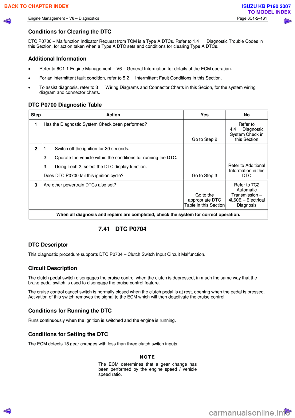
DTC P0700 – Malfunction Indicator Request from TCM is a Type A DTCs. Refer to 1.4 Diagnostic Trouble Codes in
this Section, for action taken when a Type A DTC sets and conditions for clearing Type A DTCs.
Additional Information
• Refer to 6C1-1 Engine Management – V6 – General Information for details of the ECM operation.
• For an intermittent fault condition, refer to 5.2 Intermittent Fault Conditions in this Section.
• To assist diagnosis, refer to 3 W iring Diagrams and Connector Charts in this Secion, for the system wiring
diagram and connector charts.
DTC P0700 Diagnostic Table
Step Action Yes No
1 Has the Diagnostic System Check been performed?
Go to Step 2 Refer to
4.4 Diagnostic
System Check in this Section
2 1 Switch off the ignition for 30 seconds.
2 Operate the vehicle within the conditions for running the DTC.
3 Using Tech 2, select the DTC display function.
Does DTC P0700 fail this ignition cycle? Go to Step 3 Refer to Additional
Information in this DTC
3 Are other powertrain DTCs also set?
Go to the
appropriate DTC
Table in this Section Refer to 7C2
Automatic
Transmission –
4L60E – Electrical Diagnosis
When all diagnosis and repairs are completed, check the system for correct operation.
7.41 DTC P0704
DTC Descriptor
This diagnostic procedure supports DTC P0704 – Clutch Switch Input Circuit Malfunction.
Circuit Description
The clutch pedal switch disengages the cruise control when the clutch is depressed, in much the same way that the
brake pedal switch is used to disengage the cruise control feature.
The cruise control cancel switch is normally closed when the clutch pedal is at rest, opening when the pedal is pressed.
Activation of this switch removes the signal to the ECM which will then deactivate the cruise control.
Conditions for Running the DTC
Runs continuously when the ignition is switched and the engine is running.
Conditions for Setting the DTC
The ECM detects 15 gear changes with less than three clutch switch inputs.
NOTE
The ECM determines that a gear change has
been performed by the engine speed / vehicle
speed ratio.
BACK TO CHAPTER INDEX
TO MODEL INDEX
ISUZU KB P190 2007
Page 3502 of 6020
Engine Management – V6 – Diagnostics Page 6C1-2–224
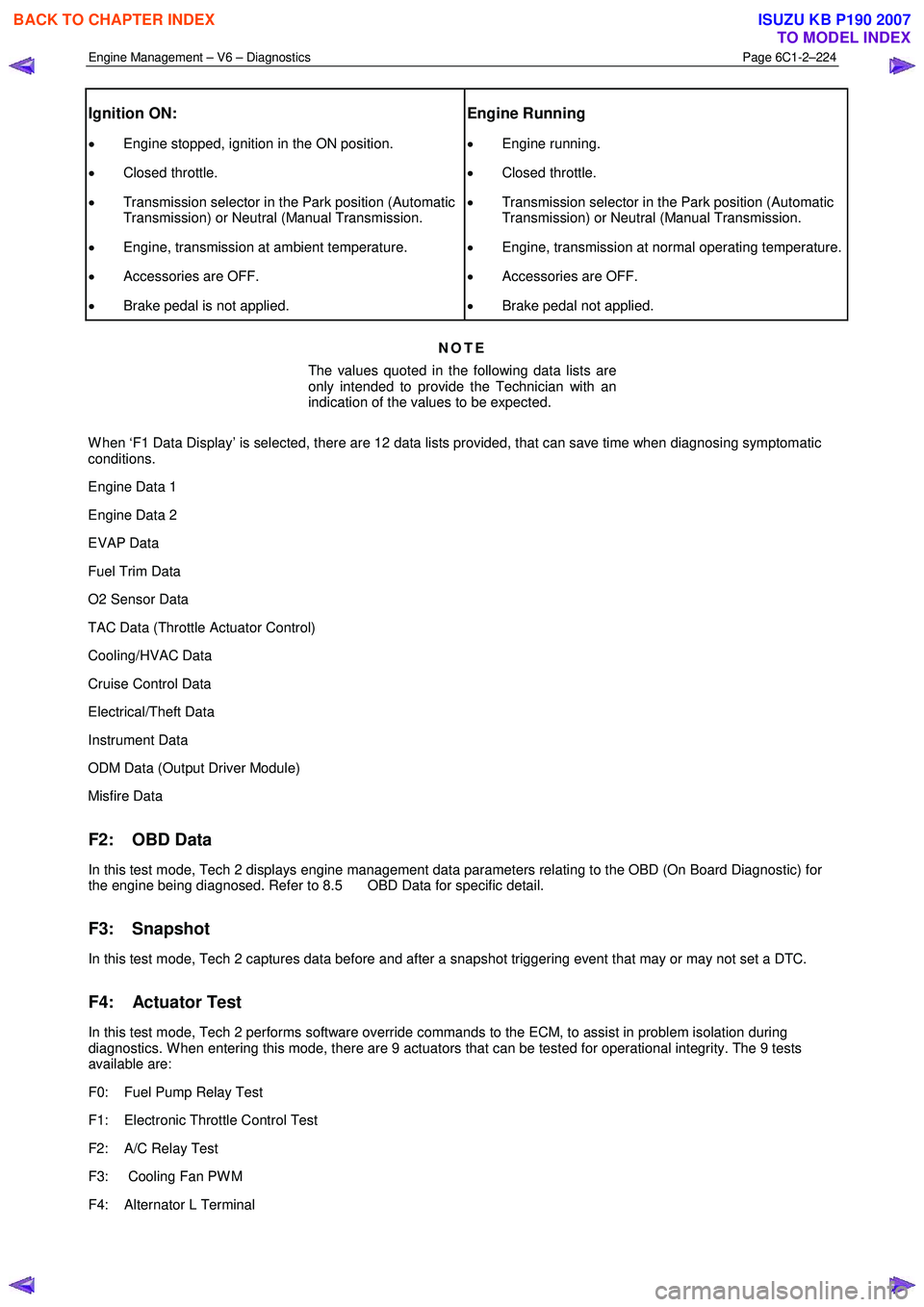
Ignition ON:
• Engine stopped, ignition in the ON position.
• Closed throttle.
• Transmission selector in the Park position (Automatic
Transmission) or Neutral (Manual Transmission.
• Engine, transmission at ambient temperature.
• Accessories are OFF.
• Brake pedal is not applied.
Engine Running
• Engine running.
• Closed throttle.
• Transmission selector in the Park position (Automatic
Transmission) or Neutral (Manual Transmission.
• Engine, transmission at normal operating temperature.
• Accessories are OFF.
• Brake pedal not applied.
NOTE
The values quoted in the following data lists are
only intended to provide the Technician with an
indication of the values to be expected.
W hen ‘F1 Data Display’ is selected, there are 12 data lists provided, that can save time when diagnosing symptomatic
conditions.
Engine Data 1
Engine Data 2
EVAP Data
Fuel Trim Data
O2 Sensor Data
TAC Data (Throttle Actuator Control)
Cooling/HVAC Data
Cruise Control Data
Electrical/Theft Data
Instrument Data
ODM Data (Output Driver Module)
Misfire Data
F2: OBD Data
In this test mode, Tech 2 displays engine management data parameters relating to the OBD (On Board Diagnostic) for
the engine being diagnosed. Refer to 8.5 OBD Data for specific detail.
F3: Snapshot
In this test mode, Tech 2 captures data before and after a snapshot triggering event that may or may not set a DTC.
F4: Actuator Test
In this test mode, Tech 2 performs software override commands to the ECM, to assist in problem isolation during
diagnostics. W hen entering this mode, there are 9 actuators that can be tested for operational integrity. The 9 tests
available are:
F0: Fuel Pump Relay Test
F1: Electronic Throttle Control Test
F2: A/C Relay Test
F3: Cooling Fan PW M
F4: Alternator L Terminal
BACK TO CHAPTER INDEX
TO MODEL INDEX
ISUZU KB P190 2007
Page 3505 of 6020
Engine Management – V6 – Diagnostics Page 6C1-2–227
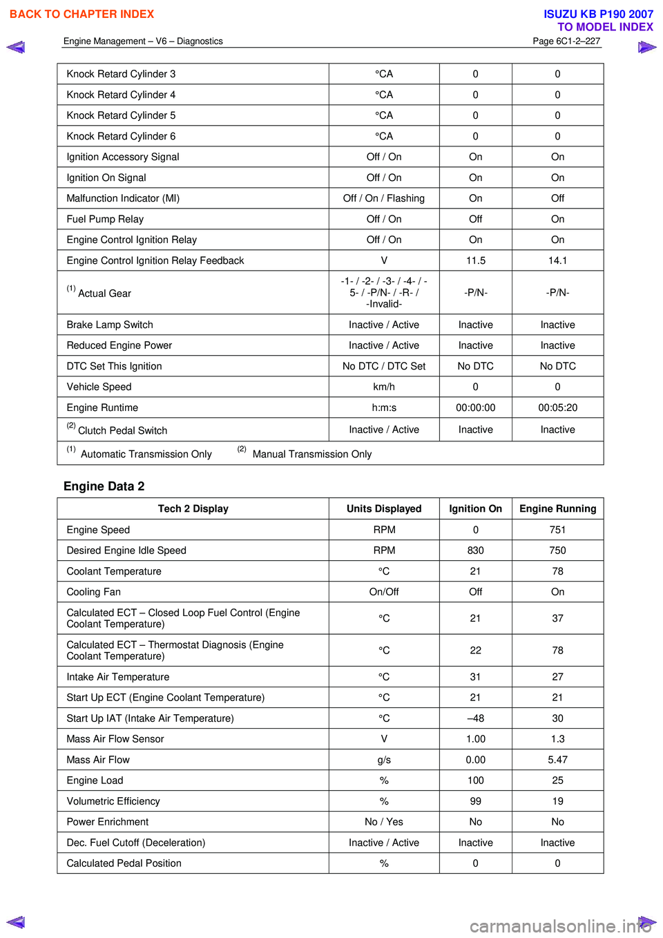
Knock Retard Cylinder 3 °CA 0 0
Knock Retard Cylinder 4 °CA 0 0
Knock Retard Cylinder 5 °CA 0 0
Knock Retard Cylinder 6 °CA 0 0
Ignition Accessory Signal Off / On On On
Ignition On Signal Off / On On On
Malfunction Indicator (MI) Off / On / Flashing On Off
Fuel Pump Relay Off / On Off On
Engine Control Ignition Relay Off / On On On
Engine Control Ignition Relay Feedback V 11.5 14.1
(1) Actual Gear -1- / -2- / -3- / -4- / -
5- / -P/N- / -R- / -Invalid- -P/N- -P/N-
Brake Lamp Switch
Inactive / Active Inactive Inactive
Reduced Engine Power Inactive / Active Inactive Inactive
DTC Set This Ignition No DTC / DTC Set No DTC No DTC
Vehicle Speed km/h 0 0
Engine Runtime h:m:s 00:00:00 00:05:20
(2) Clutch Pedal Switch Inactive / Active Inactive Inactive
(1) Automatic Transmission Only (2) Manual Transmission Only
Engine Data 2
Tech 2 Display
Units Displayed Ignition On Engine Running
Engine Speed RPM 0 751
Desired Engine Idle Speed RPM 830 750
Coolant Temperature °C 21 78
Cooling Fan On/Off Off On
Calculated ECT – Closed Loop Fuel Control (Engine
Coolant Temperature) °C 21 37
Calculated ECT – Thermostat Diagnosis (Engine
Coolant Temperature) °C 22 78
Intake Air Temperature
°C 31 27
Start Up ECT (Engine Coolant Temperature) °C 21 21
Start Up IAT (Intake Air Temperature) °C –48 30
Mass Air Flow Sensor V 1.00 1.3
Mass Air Flow g/s 0.00 5.47
Engine Load % 100 25
Volumetric Efficiency % 99 19
Power Enrichment No / Yes No No
Dec. Fuel Cutoff (Deceleration) Inactive / Active Inactive Inactive
Calculated Pedal Position % 0 0
BACK TO CHAPTER INDEX
TO MODEL INDEX
ISUZU KB P190 2007
Page 3511 of 6020
Engine Management – V6 – Diagnostics Page 6C1-2–233
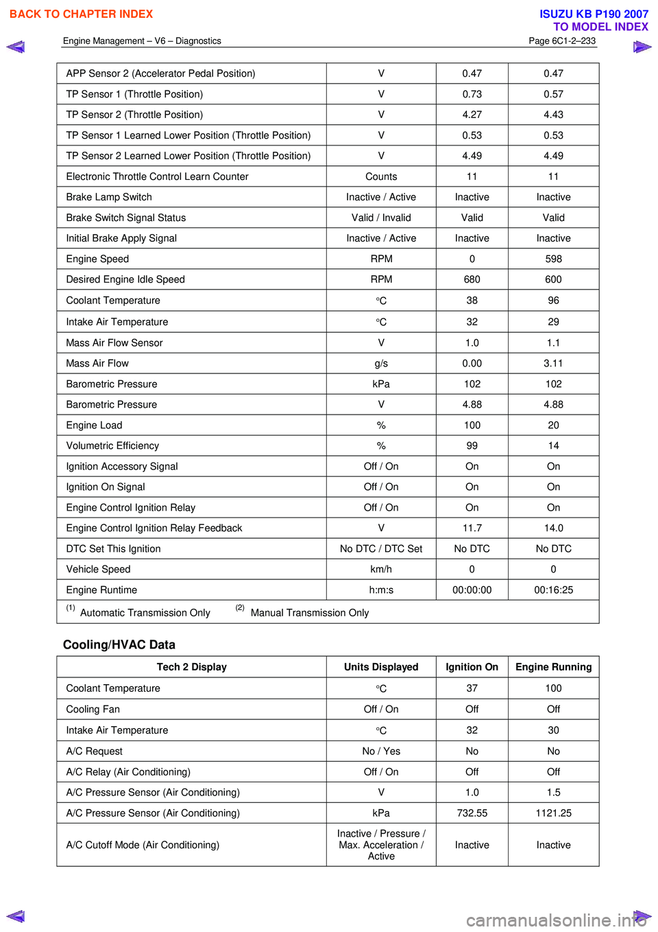
APP Sensor 2 (Accelerator Pedal Position) V 0.47 0.47
TP Sensor 1 (Throttle Position) V 0.73 0.57
TP Sensor 2 (Throttle Position) V 4.27 4.43
TP Sensor 1 Learned Lower Position (Throttle Position) V 0.53 0.53
TP Sensor 2 Learned Lower Position (Throttle Position) V 4.49 4.49
Electronic Throttle Control Learn Counter Counts 11 11
Brake Lamp Switch Inactive / Active Inactive Inactive
Brake Switch Signal Status Valid / Invalid Valid Valid
Initial Brake Apply Signal Inactive / Active Inactive Inactive
Engine Speed RPM 0 598
Desired Engine Idle Speed RPM 680 600
Coolant Temperature
°C 38 96
Intake Air Temperature
°C 32 29
Mass Air Flow Sensor
V 1.0 1.1
Mass Air Flow g/s 0.00 3.11
Barometric Pressure kPa 102 102
Barometric Pressure V 4.88 4.88
Engine Load % 100 20
Volumetric Efficiency % 99 14
Ignition Accessory Signal Off / On On On
Ignition On Signal Off / On On On
Engine Control Ignition Relay Off / On On On
Engine Control Ignition Relay Feedback V 11.7 14.0
DTC Set This Ignition No DTC / DTC Set No DTC No DTC
Vehicle Speed km/h 0 0
Engine Runtime h:m:s 00:00:00 00:16:25
(1) Automatic Transmission Only (2) Manual Transmission Only
Cooling/HVAC Data
Tech 2 Display Units Displayed Ignition On Engine Running
Coolant Temperature
°C 37 100
Cooling Fan
Off / On Off Off
Intake Air Temperature
°C 32 30
A/C Request
No / Yes No No
A/C Relay (Air Conditioning) Off / On Off Off
A/C Pressure Sensor (Air Conditioning) V 1.0 1.5
A/C Pressure Sensor (Air Conditioning) kPa 732.55 1121.25
A/C Cutoff Mode (Air Conditioning) Inactive / Pressure /
Max. Acceleration / Active Inactive Inactive
BACK TO CHAPTER INDEX
TO MODEL INDEX
ISUZU KB P190 2007
Page 3512 of 6020
Engine Management – V6 – Diagnostics Page 6C1-2–234
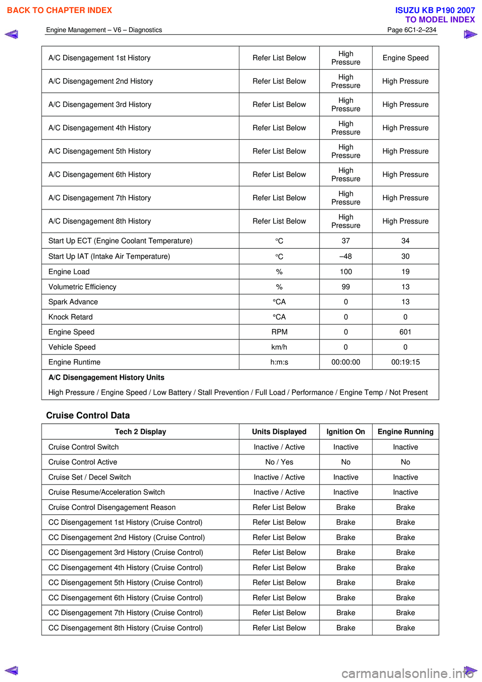
A/C Disengagement 1st History Refer List Below High
Pressure Engine Speed
A/C Disengagement 2nd History
Refer List Below High
Pressure High Pressure
A/C Disengagement 3rd History
Refer List Below High
Pressure High Pressure
A/C Disengagement 4th History
Refer List Below High
Pressure High Pressure
A/C Disengagement 5th History
Refer List Below High
Pressure High Pressure
A/C Disengagement 6th History
Refer List Below High
Pressure High Pressure
A/C Disengagement 7th History
Refer List Below High
Pressure High Pressure
A/C Disengagement 8th History
Refer List Below High
Pressure High Pressure
Start Up ECT (Engine Coolant Temperature)
°C 37 34
Start Up IAT (Intake Air Temperature)
°C –48 30
Engine Load
% 100 19
Volumetric Efficiency % 99 13
Spark Advance °CA 0 13
Knock Retard °CA 0 0
Engine Speed RPM 0 601
Vehicle Speed km/h 0 0
Engine Runtime h:m:s 00:00:00 00:19:15
A/C Disengagement History Units
High Pressure / Engine Speed / Low Battery / Stall Prevention / Full Load / Performance / Engine Temp / Not Present
Cruise Control Data
Tech 2 Display Units Displayed Ignition On Engine Running
Cruise Control Switch Inactive / Active Inactive Inactive
Cruise Control Active No / Yes No No
Cruise Set / Decel Switch Inactive / Active Inactive Inactive
Cruise Resume/Acceleration Switch Inactive / Active Inactive Inactive
Cruise Control Disengagement Reason Refer List Below Brake Brake
CC Disengagement 1st History (Cruise Control) Refer List Below Brake Brake
CC Disengagement 2nd History (Cruise Control) Refer List Below Brake Brake
CC Disengagement 3rd History (Cruise Control) Refer List Below Brake Brake
CC Disengagement 4th History (Cruise Control) Refer List Below Brake Brake
CC Disengagement 5th History (Cruise Control) Refer List Below Brake Brake
CC Disengagement 6th History (Cruise Control) Refer List Below Brake Brake
CC Disengagement 7th History (Cruise Control) Refer List Below Brake Brake
CC Disengagement 8th History (Cruise Control) Refer List Below Brake Brake
BACK TO CHAPTER INDEX
TO MODEL INDEX
ISUZU KB P190 2007