2007 ISUZU KB P190 brake
[x] Cancel search: brakePage 2549 of 6020
Engine Mechanical – V6 Page 6A1–70
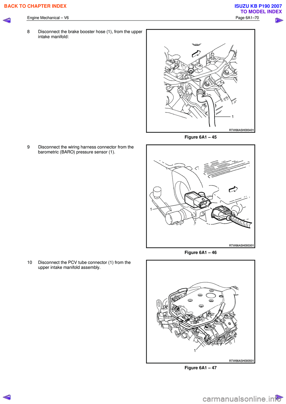
8 Disconnect the brake booster hose (1), from the upper
intake manifold:
Figure 6A1 – 45
9 Disconnect the wiring harness connector from the barometric (BARO) pressure sensor (1).
Figure 6A1 – 46
10 Disconnect the PCV tube connector (1) from the upper intake manifold assembly.
Figure 6A1 – 47
BACK TO CHAPTER INDEX
TO MODEL INDEX
ISUZU KB P190 2007
Page 2825 of 6020

Engine Mechanical – V6 Page 6A1–48
Page 6A1–48
2.18 Engine Oil Leak Diagnosis
Introduction
It is important to correctly identify the source of an engine oil leak. For example, a power steering fluid leak or spillage
during servicing can travel across the va lley area of the engine and run-out the weep hole, which is located at the back of
the cylinder block. Failure to correctly identify the source of an engine oil leak can lead to unnecessary replacement of
engine components.
Most fluid leaks can be repaired by repairi ng or replacing the faulty component or resealing the gasket surface. However,
once a leak is identified it is im portant to determine and repair the c ause as well as the leak itself.
Locating and Identifying the Leak
Inspect the leaking fluid and determine whet her it is engine oil, transmission fluid, power steering fluid, brake fluid or
some other fluid. If unsure of the source of the leaking lubricant, a quick check of fluid levels should indicate where the
fluid is coming from, as one or more fluid level should be low.
Visual Inspection
Once the type of leaking fluid has been determined, a visual inspection of the affected system should be performed.
When performing the visual inspection:
1 Bring the vehicle to the normal operating temperature.
2 Park the vehicle over a large s heet of paper or other clean surface.
3 Leave the vehicle idling for 2-3 minut es, then check for dripping fluid.
4 If required, identify the type of fluid leak ing and the approximate location of the leak.
5 Visually inspect the suspected area. A small mirror may assist viewing areas that are difficult to see normally.
6 Check for leaks at all sealing surfaces and fittings.
7 Check for any cracked or damaged components.
8 If the leak cannot be located, completely clean the entire engine and surrounding components, drive the vehicle at
normal operating temperature for several k ilometres and then repeat Steps 3 to 8.
9 If the leak still cannot be located, proceed with either the Powder Method or Black Light and Dye Method as
outlined below.
Powder Method
1 Completely clean the entir e engine and surrounding components.
2 Apply an aerosol type powder (e.g. f oot powder) to the suspected area.
3 Operate the vehicle at normal operating temperature and at varying speeds for several kilometres.
4 Identify the source of the leak from the discoloration of the powder around the suspect components.
5 If required, use a small mirror to assist in vi ewing areas that are difficult to see normally.
6 Refer to Possible Causes for Engine Oil Leaks in this Section, and repair or replace components as required.
Black Light and Dye Method
A black light and die kit Tool No. J28428-E or a commercially av ailable equivalent is available to technicians to aid in
engine oil leak diagnosis. When using a black light and die kit fo r the first time, it is recommended the technician read the
manufacturers instructions prior to using the kit.
1 Add the specified amount of dye, as per manufacturers instructions, into the engine or suspected source of the oil
leak.
2 Operate the vehicle at normal operating temperature and at varying speeds for several kilometres.
3 With the vehicle parked on a flat leve l surface, aim the black light at the suspected component/s. The dyed fluid will
appear as a yellow path leading to the oil leak source
4 Refer to Possible Causes for Engine Oil Leaks in this Section, and repair or replace components as required.
BACK TO CHAPTER INDEX
TO MODEL INDEX
ISUZU KB P190 2007
Page 2855 of 6020
Engine Mechanical – V6 Page 6A1–78
Page 6A1–78
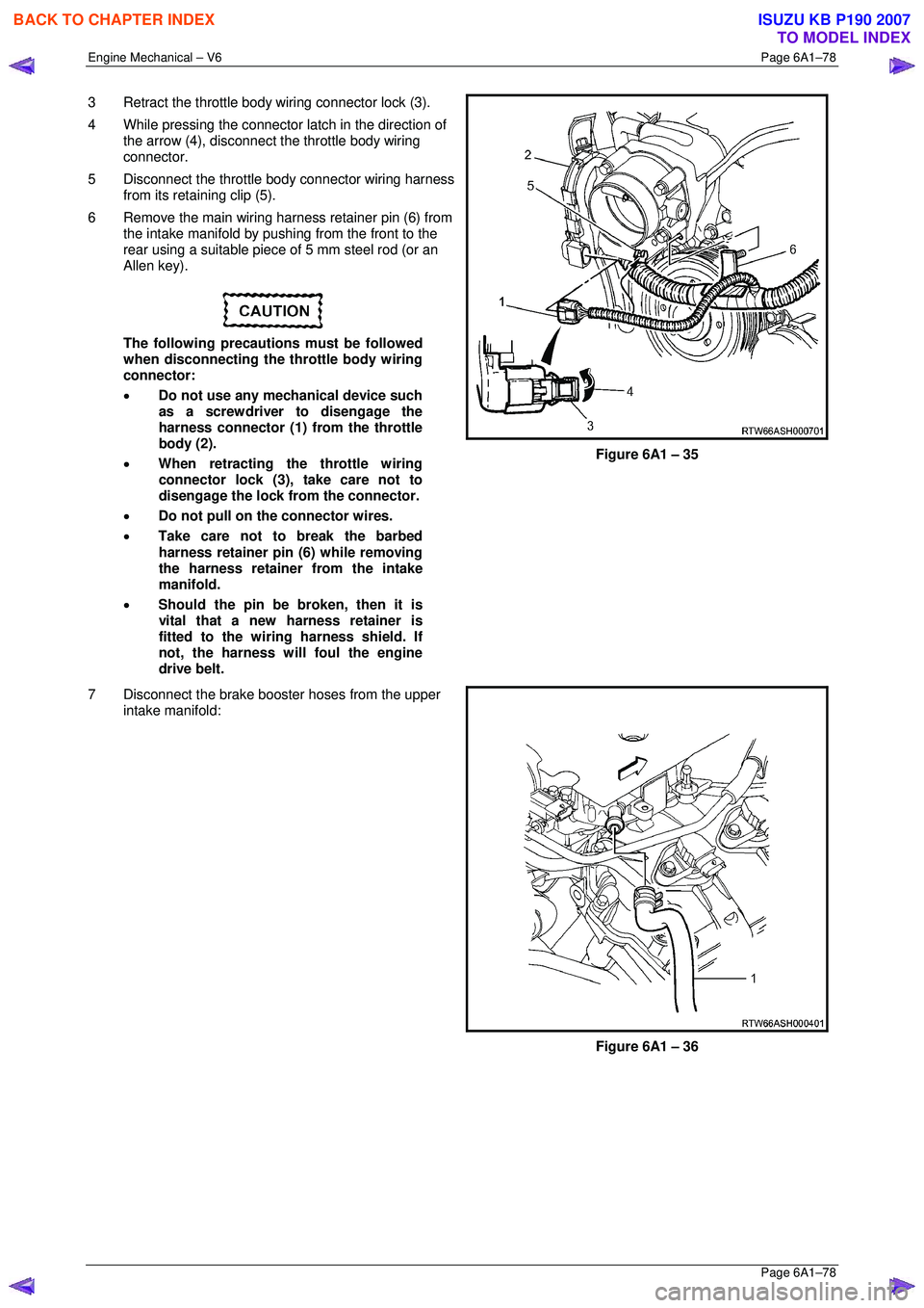
3 Retract the throttle body wiring connector lock (3).
4 While pressing the connector latch in the direction of
the arrow (4), disconnect the throttle body wiring
connector.
5 Disconnect the throttle body connector wiring harness from its retaining clip (5).
6 Remove the main wiring harness retainer pin (6) from the intake manifold by pushing from the front to the
rear using a suitable piece of 5 mm steel rod (or an
Allen key).
The following precautions must be followed
when disconnecting the throttle body wiring
connector:
• Do not use any mechanical device such
as a screwdriver to disengage the
harness connector (1) from the throttle
body (2).
• When retracting the throttle wiring
connector lock (3), take care not to
disengage the lock from the connector.
• Do not pull on the connector wires.
• Take care not to break the barbed
harness retainer pin (6) while removing
the harness retainer from the intake
manifold.
• Should the pin be broken, then it is
vital that a new harness retainer is
fitted to the wiring harness shield. If
not, the harness will foul the engine
drive belt.
Figure 6A1 – 35
7 Disconnect the brake booster hoses from the upper intake manifold:
Figure 6A1 – 36
BACK TO CHAPTER INDEX
TO MODEL INDEX
ISUZU KB P190 2007
Page 2861 of 6020
Engine Mechanical – V6 Page 6A1–84
Page 6A1–84
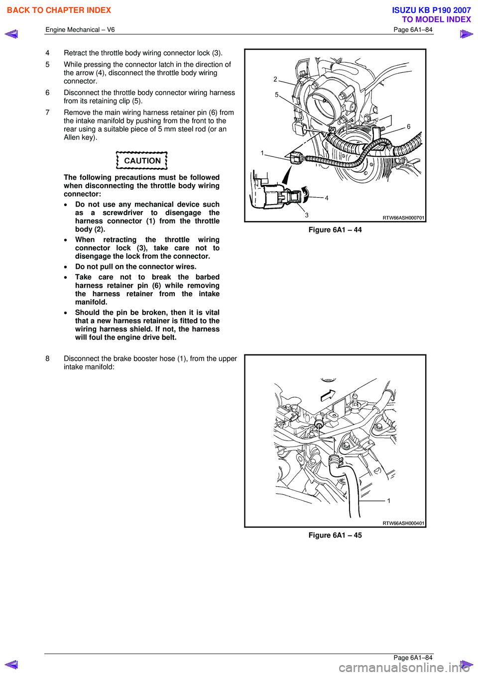
4 Retract the throttle body wiring connector lock (3).
5 While pressing the connector latch in the direction of
the arrow (4), disconnect the throttle body wiring
connector.
6 Disconnect the throttle body connector wiring harness from its retaining clip (5).
7 Remove the main wiring harness retainer pin (6) from the intake manifold by pushing from the front to the
rear using a suitable piece of 5 mm steel rod (or an
Allen key).
The following precautions must be followed
when disconnecting the throttle body wiring
connector:
• Do not use any mechanical device such
as a screwdriver to disengage the
harness connector (1) from the throttle
body (2).
• When retracting the throttle wiring
connector lock (3), take care not to
disengage the lock from the connector.
• Do not pull on the connector wires.
• Take care not to break the barbed
harness retainer pin (6) while removing
the harness retainer from the intake
manifold.
• Should the pin be broken, then it is vital
that a new harness retainer is fitted to the
wiring harness shield. If not, the harness
will foul the engine drive belt.
Figure 6A1 – 44
8 Disconnect the brake booster hose (1), from the upper
intake manifold:
Figure 6A1 – 45
BACK TO CHAPTER INDEX
TO MODEL INDEX
ISUZU KB P190 2007
Page 3157 of 6020
Engine Cooling – V6 Engine Page 6B1–22
3.3 Draining and Filling Cooling System
Draining
Refer to 3.1 Service Notes in this Section, for
important safety items.
1 Allow engine to cool to ambient temperature (less than 50 ° C), and then remove the coolant filler cap (located near
the brake booster assembly).
Disconnection of the battery affects certain
vehicle electronic systems. Refer to 1.1
WARNING, CAUTION and NOTES, before
removing the ground lead.
2 Disconnect the battery ground lead. Refer to 6D1– 3 Battery – V6.
3 Drain the coolant from the system via the radiator drain tap on the lower RHS of the radiator below the lower hose outlet. Attach a suitable piece of rubber tubing to the tap outlet to help direct the flow of the coolant into a suitable
container (capacity at least 12 litres).
Filling
During any service operation that requires the cooling system to be partly or completely drained, the following
instructions must be followed when refilling the cooling system, to ensure that all air is bleed from system.
• Refer to 3.1 Service Notes in this Section,
for important safety items.
• Before opening the radiator bleed screw,
the cooling system must first be
completely depressurised with the engine
coolant filler cap removed.
Do not mix different types of anti-freeze or
corrosion inhibitors, as they may be
incompatible. Always check which coolant is
to be added to the particular vehicle being
serviced. If a different type has been used in
the cooling system (or is added accidentally),
flush the system with clean water. Refer to 3.4
Cleaning Cooling System in this Section.
NOTE
Ensure that the radiator drain tap located at the
bottom of right-hand side radiator tank is closed
before proceeding.
BACK TO CHAPTER INDEX
TO MODEL INDEX
ISUZU KB P190 2007
Page 3243 of 6020
Engine Management – V6 – General Information Page 6C1-1–1
6C1-1 Engine Management – V6
General Information
ATTENTION
Before performing any service operation or other procedure described in this Section, refer to 1.3 Warning
Caution and Notes for correct workshop practices with regard to safety and / or property damage.
1 General Information ............................................................................................................ ...................3
1.1 Introduction ............................................................................................................................................................ 3
1.2 Emission Control ................................................................................................................................................... 3
ADR 79/01 Emissions Standards .......................................................................................................................... 3
1.3 Warning Caution and Notes .................................................................................................................................. 4
Definition of WARNING, CAUTION and NOTE Statements ............................................................................. .... 4
WARNING defined ............................................................................................................................................. 4
CAUTION defined .............................................................................................................................................. 4
NOTE defined..................................................................................................................................................... 4
2 Component Locations ............................................................................................................ ...............5
2.1 Cylinder Numbering............................................................................................................................................... 5
2.2 Engine Compartment............................................................................................................................................. 5
2.3 Engine ..................................................................................................................................................................... 6
2.4 Interior..................................................................................................................................................................... 8
3 System Operation ...................................................................................................................................9
3.1 Fuel Delivery System ............................................................................................................................................. 9
Fuel System Pressure ........................................................................................................... ................................ 9
Fuel Injection System .......................................................................................................................................... 10
Short Term Fuel Trim ....................................................................................................................................... 10
Long Term Fuel Trim ........................................................................................................................................ 10
3.2 Air / Fuel Control System ...................................................................................................... .............................. 11
Starting Mode ....................................................................................................................................................... 11
Run Mode.............................................................................................................................................................. 11
Open Loop Mode................................................................................................................. ............................. 11
Closed Loop Mode ............................................................................................................... ............................ 11
Acceleration Mode .............................................................................................................. ................................. 11
Deceleration Mode ............................................................................................................................................... 11
Fuel Shut-off Mode .............................................................................................................................................. 11
Battery Voltage Correction Mode ................................................................................................ ....................... 12
Limp Mode ............................................................................................................................................................ 12
Engine Protection Mode ......................................................................................................... ............................. 12
Clear Flood Mode ................................................................................................................................................. 12
3.3 Ignition Control System........................................................................................................ ............................... 12
3.4 Starter Motor Operation....................................................................................................................................... 12
3.5 Throttle Actuator Control System ............................................................................................... ....................... 12
Description ........................................................................................................................................................... 12
Throttle Body Relearn Procedure ....................................................................................................................... 14
TAC System Default Actions / Reduce Power Modes................................................................................ ....... 14
Forced Engine Shutdown .................................................................................................................................... 14
3.6 Cruise Control System ........................................................................................................................................ 14
3.7 Brake Torque Management ........................................................................................................ ......................... 15
3.8 Emission Control Systems.................................................................................................................................. 15
Evaporative Emission Control System ............................................................................................ .................. 15
Engine Ventilation System .................................................................................................................................. 16
BACK TO CHAPTER INDEX
TO MODEL INDEX
ISUZU KB P190 2007
Page 3244 of 6020
Engine Management – V6 – General Information Page 6C1-1–2
3.9 Serial Data Communication System ................................................................................................................... 17
3.10 Self Diagnostics System ..................................................................................................................................... 17
3.11 Service Programming System ..................................................................................................... ....................... 17
3.12 Immobiliser System ............................................................................................................................................. 18
4 Component Description and Operation ............................................................................................ .19
4.1 A/C Refrigerant Pressure Sensor ....................................................................................................................... 19
4.2 Brake Pedal Switch Assembly ............................................................................................................................ 19
Stop Lamp and Initial Brake Apply Switch ....................................................................................... ................. 19
Stop Lamp Switch ............................................................................................................................................ 19
Initial Brake Apply Switch ..................................................................................................... ............................ 19
4.3 Barometric Pressure Sensor..................................................................................................... .......................... 20
4.4 Camshaft Position Sensor .................................................................................................................................. 20
4.5 Crankshaft Position Sensor ................................................................................................................................ 21
4.6 Clutch Pedal Switch Assembly – Manual Vehicles Only ............................................................................ ...... 22
4.7 Engine Control Module........................................................................................................................................ 22
4.8 Engine Coolant Temperature Sensor .............................................................................................. ................... 23
4.9 Electric Cooling Fans .......................................................................................................................................... 23
4.10 Engine Oil Level and Temperature Sensor ........................................................................................ ................ 24
Engine Oil Temperature Sensor ......................................................................................................................... 24
Engine Oil Level Sensor ...................................................................................................................................... 25
4.11 Engine Oil Pressure Sensor..................................................................................................... ........................... 25
4.12 Fuel Injectors........................................................................................................................................................ 26
4.13 Fuel Rail Assembly ............................................................................................................. ................................. 27
4.14 Heated Oxygen Sensors .......................................................................................................... ............................ 27
LSF 4.2 Two-step Planar Heated Oxygen Sensors .................................................................................. ......... 27
LSU 4.2 Wide-band Planar Heated Oxygen Sensors ................................................................................. ....... 29
4.15 Ignition Coil and Spark Plug ............................................................................................................................... 31
4.16 Intake Air Temperature Sensor .................................................................................................. ......................... 32
4.17 Knock Sensor ....................................................................................................................................................... 32
4.18 Mass Air Flow Sensor........................................................................................................... ............................... 33
Air Intake System ................................................................................................................................................. 33
Mass Air Flow Sensor........................................................................................................... ............................... 33
Construction ..................................................................................................................................................... 34
Operation ......................................................................................................................................................... 34
5 Abbreviations and Glossary of Terms ............................................................................................ ...35
BACK TO CHAPTER INDEX
TO MODEL INDEX
ISUZU KB P190 2007
Page 3250 of 6020
Engine Management – V6 – General Information Page 6C1-1–8
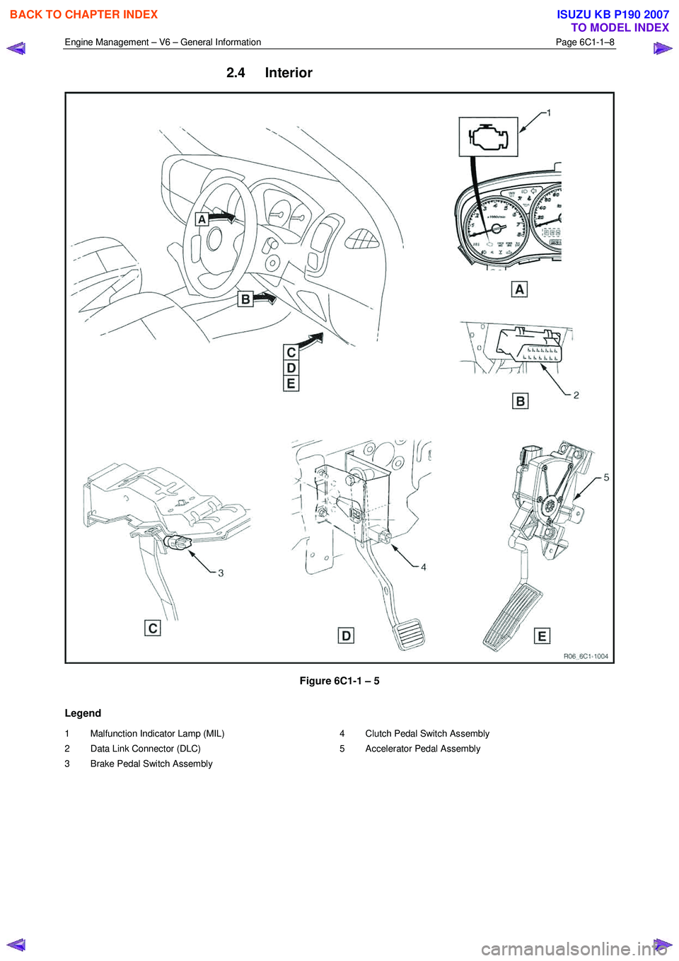
2.4 Interior
Figure 6C1-1 – 5
Legend
1 Malfunction Indicator Lamp (MIL)
2 Data Link Connector (DLC)
3 Brake Pedal Switch Assembly 4 Clutch Pedal Switch Assembly
5 Accelerator Pedal Assembly
BACK TO CHAPTER INDEX
TO MODEL INDEX
ISUZU KB P190 2007