2007 ISUZU KB P190 brake
[x] Cancel search: brakePage 2110 of 6020
6B-6 ENGINE COOLING
Draining and Refilling Cooling
System
Before draining the cooling system, inspect the system and
perform any necessary service to ensure that it is clean, does
not leak and is in proper working order. The engine coolant
level should be between the "MIN" and "MAX" lines of reserve
tank when the engine is cold. If low, check for leakage and add
engine coolant up to the "MAX" line. There should not be any
excessive deposit of rust or scales around the radiator cap or
radiator filler hole, and the engine coolant should also be free
from oil.
Replace the engine coolant if excessively dirty.
1. Completely drain the cooling system by opening the drain
plug at the bottom of the radiator.
2. Remove the radiator cap.
WARNING: TO AVOID THE DANGER OF BEING BURNED,
DO NOT REMOVE THE CAP WHILE THE ENGINE AND
RADIATOR ARE STILL HOT. SCALDING FLUID AND
STEAM CAN BE BLOWN OUT UNDER PRESSURE.
3. Disconnect all hoses from the engine coolant reserve tank.
Scrub and clean the inside of the reserve tank with soap and water. Flush it well with clean water, then drain it. Install
the reserve tank and hoses.
4. Refill the cooling system with the engine coolant using a solution that is at least 50 percent antifreeze.
5. Fill the radiator to the base of the filler neck.
Fill the engine coolant reserve tank to "MAX" line when the engine is cold.
6. Block the drive wheels and firmly apply the parking brake and place the shift lever in the "NEUTRAL" position.
7. Remove the radiator cap. Start the engine and warm it up at 2,500 - 3,000 rpm for about 30 minutes.
8. W hen the air comes out from the radiator filler neck and the engine coolant level has gone down, replenish with the
engine coolant. Repeat this procedure until the engine
coolant level does not go down. Then stop the engine and
install the radiator cap. Let the engine cool down.
9. After the engine has cooled, replenish with engine coolant up to the "MAX" line of the reserve tank.
10. Start the engine. W ith the engine running at 3,000 rpm, make sure there is no running water sound from the heate
r
core (behind the center console).
11. If the running water sound is heard, repeat steps 8 to 10.
BACK TO CHAPTER INDEX
TO MODEL INDEX
ISUZU KB P190 2007
Page 2142 of 6020
ENGINE ELECTRICAL 6D1-5
Battery fluid is a highly corrosive acid.
Should battery fluid come in contact with your eyes, skin,
fabric, or a painted surface, immediately and thoroughly rinse
the affected area with clean tap water.
Never allow metal tools or jumper cables to come in contact
with the positive battery terminal, or any other metal surface of
the vahicle. This will protect against a short circuit.
Always keep batteries out of reach of young children.
Jump Starting Procedure
1. Set the vehicle parking brake and place the shift lever in the
"NEUTRAL" position.
Turn "OFF" the ignition.
Turn "OFF" all lights and any other accessory requiring electrical power.
2. Look at the built-in hydrometer.
If the indication area of the built-in hydrometer is completel
y
clear, do not try to jump start.
3.
Attach the end of one jumper cable to the positive terminal
of the booster battery.
Attach the other end of the same cable to the positive
terminal of the discharged battery.
Do not allow the vehicles to touch each other. This will cause a ground connection, effectively neutralizing the
charging procedure.
Be sure that the booster battery has a 12 volt rating.
4.
Attach one end of the remaining cable to the negative
terminal of the booster battery.
Attach the other end of the same cable to a solid engine ground (such as the air conditioning compressor bracket o
r
the generator mounting bracket) of the vehicle with the
discharged battery.
The ground connection must be at least 450 mm (18 in.) from the battery of the vehicle whose battery is being
charged.
WARNING: NEVER ATTACH THE END OF THE JUMPER
CABLE DIRECTLY TO THE NEGATIVE TERMINAL OF THE
DEAD BATTERY.
5. Start the engine of the vehicle with the good battery.
Make sure that all unnecessary electrical accessories have been turned "OFF".
6. Start the engine of the vehicle with the dead battery.
7. To remove the jumper cables, follow the above directions in reverse order.
Be sure to first disconnect the negative cable from the vehicle with the discharged battery.
BACK TO CHAPTER INDEX
TO MODEL INDEX
ISUZU KB P190 2007
Page 2403 of 6020
ENGINE DRIVEABILITY AND EMISSIONS 6E–233
ENGINE CRANKS BUT WILL NOT RUN
DEFINITIONS: Engine cranks, but will not run. (The engine never start.)
NOTE: The replacement ECM must be programmed. Refer to section of the Service Programming System (SPS) in
this manual. Following ECM programming, the immobilizer system (if equipped) must be linked to the ECM.
Refer to section 11 “Immobilizer System-ECM replacement” for the ECM/Immobilizer linking procedure.
NOTE: The vehicle with immobilizer system, this system may be activated. Check the immobilizer system diagosis.
Step Action Value(s) Yes No
1 Was the “ On-Board Diagnostic (OBD) System Check ”
performed? — Go to Step 2Go to
OBD
System Check
2 1. Perform a bulletin search. 2. If a bulletin that addresses the symptom is found,correct the condition as instructed in the bulletin.
Was a bulletin found that addresses the symptom? — Verify repair Go to Step 3
3 Was a visually/physical check performed? —Go to Step 4Go to
Visual /
physical Check.
4 Check the “Ignition coil” fuse (15A) and “ECM” fuse (15A).
Was a fuse blown? — Verify repair Go to Step 5
5 1. Ignition ON 2. Use a DVM to verify that battery voltage at theignition coil fuse, and the ECM fuse.
Was battery voltage presented at the fuses? — Go to Step 6Verify & repair
6 1. Visually/physically inspect for the following conditions:
• Restriction of air intake system. Check for a restricted air filter element, or foreign objects
blocking the air intake system.
• Check for objects blocking the IAC passage or throttle bore, excessive deposits in the throttle
bore and on the throttle plate.
• Check for a condition that causes a large vacuum leak, such as an incorrectly installed or
faulty crankcase ventilation hose/brake booster
hose.
Was a problem found? — Verify repair Go to Step 7
7 1. Using a Tech 2, display the IAC value. 2. Check for a faulty, plugged, or sticking IACoperation.
Was the problem found? — Verify repair Go to Step 8
8 1. Using a Tech 2, display the MAP sensor value. 2. Check for a faulty, plugged, or incorrectly installedMAP sensor.
Was the problem found? — Verify repair Go to Step 9
9 If oscilloscope is available, check the wave form of the CKP signal.
Was the correct wave form found? — Go to Step 12Go to Step 10
10 Check the CKP sensor wire for open or short circuit. Was a problem found? — Verify repair Go to Step 11
11 Replace CKP sensor. Is there still problem? —Replace pulsar
ring. Verify repair
BACK TO CHAPTER INDEX
TO MODEL INDEX
ISUZU KB P190 2007
Page 2406 of 6020
6E–236 ENGINE DRIVEABILITY AND EMISSIONS
HARD START SYMPTOM
DEFINITIONS: Engine cranks, but does not start for a long time. Does eventually start, of may start and then
immediately stall.
Step Action Value(s) Yes No
1 Was the “ On-Board Diagnostic (OBD) System Check ”
performed? — Go to Step 2Go to
OBD
System Check
2 1. Perform a bulletin search. 2. If a bulletin that addresses the symptom is found,correct the condition as instructed in the bulletin.
Was a bulletin found that addresses the symptom? — Verify repair Go to Step 3
3 Was a visually/physical check performed? —Go to Step 4Go to
Visual /
physical Check.
4 1. Visually/physically inspect for the following conditions:
• Restriction of air intake system. Check for a restricted air filter element, or foreign objects
blocking the air intake system
• Check for objects blocking the IAC passage or throttle bore, excessive deposits in the throttle
bore and on the throttle plate
• Check for a condition that causes a large vacuum leak, such as an incorrectly installed or
faulty crankcase ventilation hose/brake booster
hose.
Was a problem found? — Verify repair Go to Step 5
5 1. Using a Tech 2, display the IAC value. 2. Check for a faulty, plugged, or sticking IACoperation.
Was the problem found? — Verify repair Go to Step 6
6 Check engine coolant temperature (ECT) sensor for shift in value.
1. After 8 hours with hood up and the engine not running, connect the Tech 2.
2. Ignition On, engine not running.
3. Using Tech 2, compare Engine Coolant Temperature to Intake Air Temperature.
Are ECT and IAT within the specified value of each
other? ± 5°C Go to Step 8Go to Step 7
BACK TO CHAPTER INDEX
TO MODEL INDEX
ISUZU KB P190 2007
Page 2409 of 6020
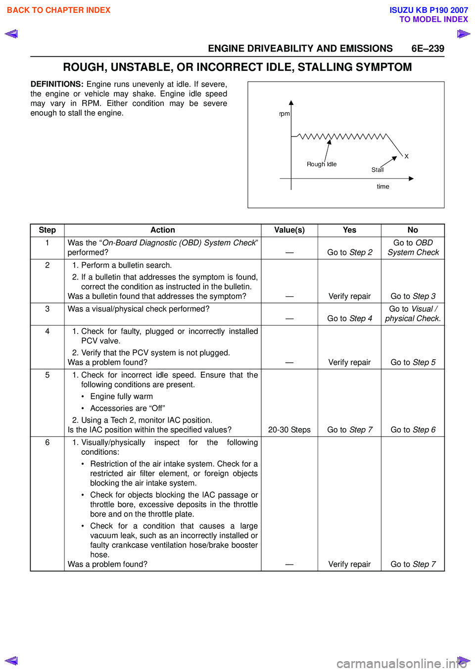
ENGINE DRIVEABILITY AND EMISSIONS 6E–239
ROUGH, UNSTABLE, OR INCORRECT IDLE, STALLING SYMPTOM
DEFINITIONS: Engine runs unevenly at idle. If severe,
the engine or vehicle may shake. Engine idle speed
may vary in RPM. Either condition may be severe
enough to stall the engine.
Step Action Value(s) Yes No
1 Was the “ On-Board Diagnostic (OBD) System Check ”
performed? — Go to Step 2Go to
OBD
System Check
2 1. Perform a bulletin search. 2. If a bulletin that addresses the symptom is found,correct the condition as instructed in the bulletin.
Was a bulletin found that addresses the symptom? — Verify repair Go to Step 3
3 Was a visual/physical check performed? —Go to Step 4Go to
Visual /
physical Check.
4 1. Check for faulty, plugged or incorrectly installed PCV valve.
2. Verify that the PCV system is not plugged.
Was a problem found? — Verify repair Go to Step 5
5 1. Check for incorrect idle speed. Ensure that the following conditions are present.
• Engine fully warm
• Accessories are “Off”
2. Using a Tech 2, monitor IAC position.
Is the IAC position within the specified values? 20-30 Steps Go to Step 7Go to Step 6
6 1. Visually/physically inspect for the following conditions:
• Restriction of the air intake system. Check for a restricted air filter element, or foreign objects
blocking the air intake system.
• Check for objects blocking the IAC passage or throttle bore, excessive deposits in the throttle
bore and on the throttle plate.
• Check for a condition that causes a large vacuum leak, such as an incorrectly installed or
faulty crankcase ventilation hose/brake booster
hose.
Was a problem found? — Verify repair Go to Step 7
BACK TO CHAPTER INDEX
TO MODEL INDEX
ISUZU KB P190 2007
Page 2419 of 6020
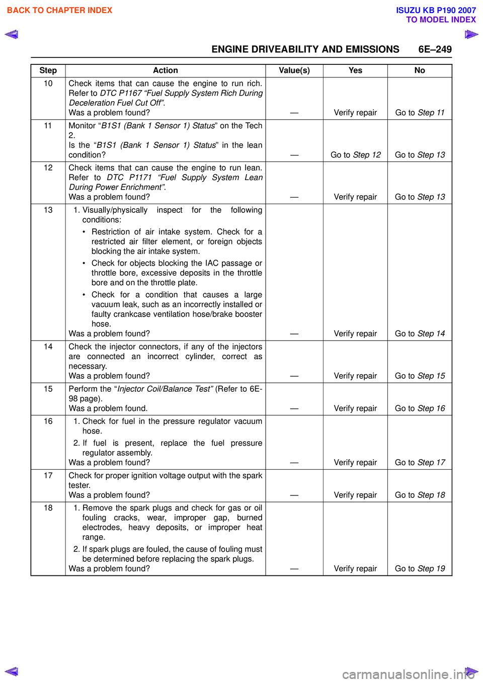
ENGINE DRIVEABILITY AND EMISSIONS 6E–249
10 Check items that can cause the engine to run rich.Refer to DTC P1167 “Fuel Supply System Rich During
Deceleration Fuel Cut Off” .
Was a problem found? — Verify repair Go to Step 11
11 Monitor “ B1S1 (Bank 1 Sensor 1) Status ” on the Tech
2.
Is the “ B1S1 (Bank 1 Sensor 1) Status ” in the lean
condition? — Go to Step 12Go to Step 13
12 Check items that can cause the engine to run lean. Refer to DTC P1171 “Fuel Supply System Lean
During Power Enrichment” .
Was a problem found? — Verify repair Go to Step 13
13 1. Visually/physically inspect for the following conditions:
• Restriction of air intake system. Check for a restricted air filter element, or foreign objects
blocking the air intake system.
• Check for objects blocking the IAC passage or throttle bore, excessive deposits in the throttle
bore and on the throttle plate.
• Check for a condition that causes a large vacuum leak, such as an incorrectly installed or
faulty crankcase ventilation hose/brake booster
hose.
Was a problem found? — Verify repair Go to Step 14
14 Check the injector connectors, if any of the injectors are connected an incorrect cylinder, correct as
necessary.
Was a problem found? — Verify repair Go to Step 15
15 Perform the “ Injector Coil/Balance Test” (Refer to 6E-
98 page).
Was a problem found. — Verify repair Go to Step 16
16 1. Check for fuel in the pressure regulator vacuum hose.
2. If fuel is present, replace the fuel pressure regulator assembly.
Was a problem found? — Verify repair Go to Step 17
17 Check for proper ignition voltage output with the spark tester.
Was a problem found? — Verify repair Go to Step 18
18 1. Remove the spark plugs and check for gas or oil fouling cracks, wear, improper gap, burned
electrodes, heavy deposits, or improper heat
range.
2. If spark plugs are fouled, the cause of fouling must be determined before replacing the spark plugs.
Was a problem found? — Verify repair Go to Step 19
Step
Action Value(s) Yes No
BACK TO CHAPTER INDEX
TO MODEL INDEX
ISUZU KB P190 2007
Page 2519 of 6020
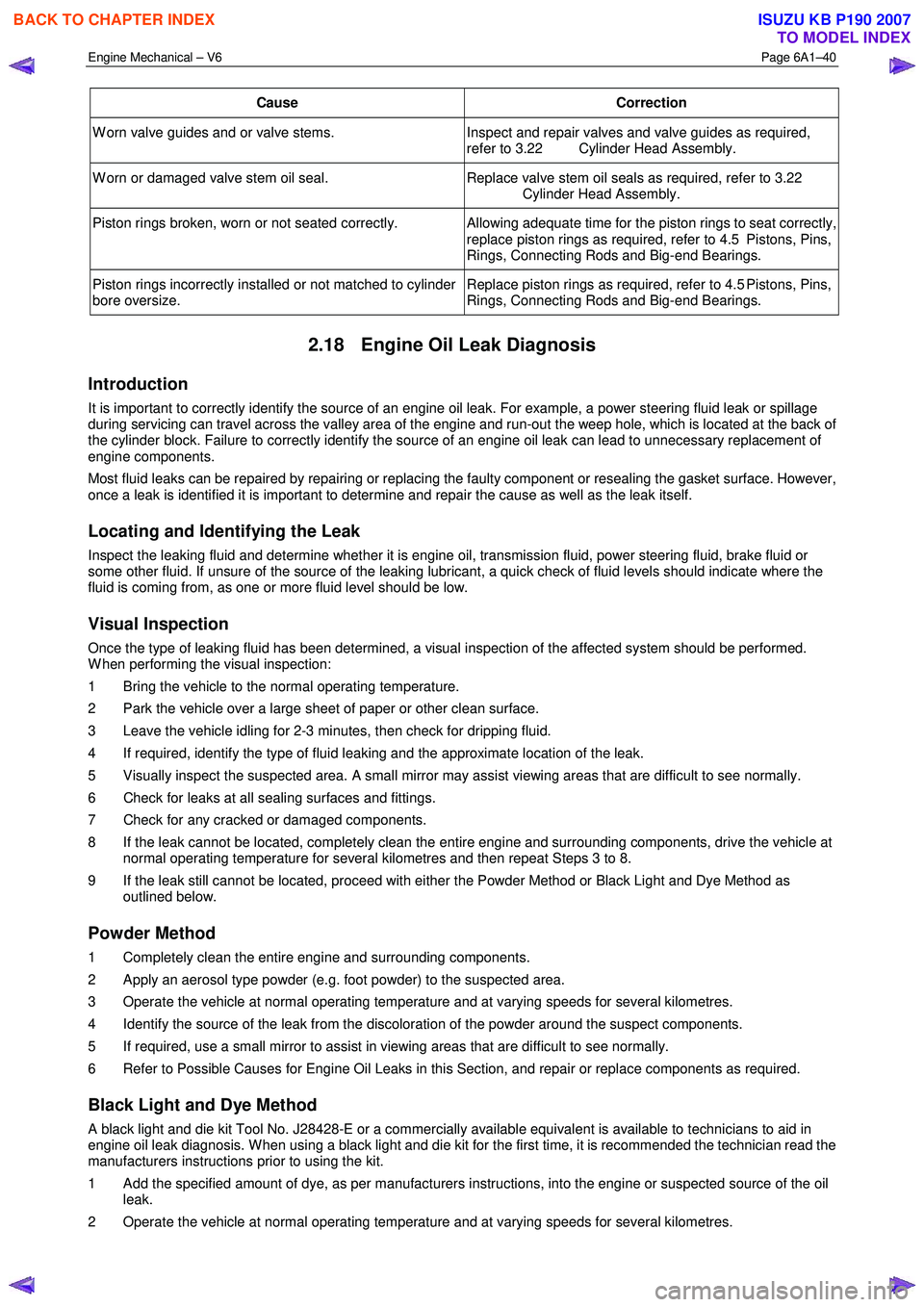
Engine Mechanical – V6 Page 6A1–40
Cause Correction
W orn valve guides and or valve stems. Inspect and repair valves and valve guides as required,
refer to 3.22 Cylinder Head Assembly.
W orn or damaged valve stem oil seal. Replace valve stem oil seals as required, refer to 3.22
Cylinder Head Assembly.
Piston rings broken, worn or not seated correctly. Allowing adequate time for the piston rings to seat correctly,
replace piston rings as required, refer to 4.5 Pistons, Pins,
Rings, Connecting Rods and Big-end Bearings.
Piston rings incorrectly installed or not matched to cylinder
bore oversize. Replace piston rings as required, refer to 4.5 Pistons, Pins,
Rings, Connecting Rods and Big-end Bearings.
2.18 Engine Oil Leak Diagnosis
Introduction
It is important to correctly identify the source of an engine oil leak. For example, a power steering fluid leak or spillage
during servicing can travel across the valley area of the engine and run-out the weep hole, which is located at the back of
the cylinder block. Failure to correctly identify the source of an engine oil leak can lead to unnecessary replacement of
engine components.
Most fluid leaks can be repaired by repairing or replacing the faulty component or resealing the gasket surface. However,
once a leak is identified it is important to determine and repair the cause as well as the leak itself.
Locating and Identifying the Leak
Inspect the leaking fluid and determine whether it is engine oil, transmission fluid, power steering fluid, brake fluid or
some other fluid. If unsure of the source of the leaking lubricant, a quick check of fluid levels should indicate where the
fluid is coming from, as one or more fluid level should be low.
Visual Inspection
Once the type of leaking fluid has been determined, a visual inspection of the affected system should be performed.
W hen performing the visual inspection:
1 Bring the vehicle to the normal operating temperature.
2 Park the vehicle over a large sheet of paper or other clean surface.
3 Leave the vehicle idling for 2-3 minutes, then check for dripping fluid.
4 If required, identify the type of fluid leaking and the approximate location of the leak.
5 Visually inspect the suspected area. A small mirror may assist viewing areas that are difficult to see normally.
6 Check for leaks at all sealing surfaces and fittings.
7 Check for any cracked or damaged components.
8 If the leak cannot be located, completely clean the entire engine and surrounding components, drive the vehicle at normal operating temperature for several kilometres and then repeat Steps 3 to 8.
9 If the leak still cannot be located, proceed with either the Powder Method or Black Light and Dye Method as outlined below.
Powder Method
1 Completely clean the entire engine and surrounding components.
2 Apply an aerosol type powder (e.g. foot powder) to the suspected area.
3 Operate the vehicle at normal operating temperature and at varying speeds for several kilometres.
4 Identify the source of the leak from the discoloration of the powder around the suspect components.
5 If required, use a small mirror to assist in viewing areas that are difficult to see normally.
6 Refer to Possible Causes for Engine Oil Leaks in this Section, and repair or replace components as required.
Black Light and Dye Method
A black light and die kit Tool No. J28428-E or a commercially available equivalent is available to technicians to aid in
engine oil leak diagnosis. W hen using a black light and die kit for the first time, it is recommended the technician read the
manufacturers instructions prior to using the kit.
1 Add the specified amount of dye, as per manufacturers instructions, into the engine or suspected source of the oil leak.
2 Operate the vehicle at normal operating temperature and at varying speeds for several kilometres.
BACK TO CHAPTER INDEX
TO MODEL INDEX
ISUZU KB P190 2007
Page 2543 of 6020
Engine Mechanical – V6 Page 6A1–64
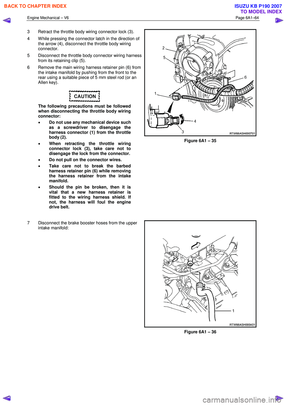
3 Retract the throttle body wiring connector lock (3).
4 W hile pressing the connector latch in the direction of the arrow (4), disconnect the throttle body wiring
connector.
5 Disconnect the throttle body connector wiring harness from its retaining clip (5).
6 Remove the main wiring harness retainer pin (6) from the intake manifold by pushing from the front to the
rear using a suitable piece of 5 mm steel rod (or an
Allen key).
The following precautions must be followed
when disconnecting the throttle body wiring
connector:
• Do not use any mechanical device such
as a screwdriver to disengage the
harness connector (1) from the throttle
body (2).
• When retracting the throttle wiring
connector lock (3), take care not to
disengage the lock from the connector.
• Do not pull on the connector wires.
• Take care not to break the barbed
harness retainer pin (6) while removing
the harness retainer from the intake
manifold.
• Should the pin be broken, then it is
vital that a new harness retainer is
fitted to the wiring harness shield. If
not, the harness will foul the engine
drive belt.
Figure 6A1 – 35
7 Disconnect the brake booster hoses from the upper intake manifold:
Figure 6A1 – 36
BACK TO CHAPTER INDEX
TO MODEL INDEX
ISUZU KB P190 2007