2007 ISUZU KB P190 brake
[x] Cancel search: brakePage 3513 of 6020
Engine Management – V6 – Diagnostics Page 6C1-2–235
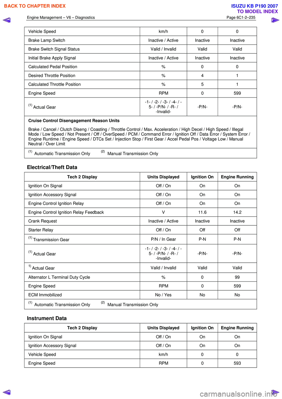
Vehicle Speed km/h 0 0
Brake Lamp Switch Inactive / Active Inactive Inactive
Brake Switch Signal Status Valid / Invalid Valid Valid
Initial Brake Apply Signal Inactive / Active Inactive Inactive
Calculated Pedal Position % 0 0
Desired Throttle Position % 4 1
Calculated Throttle Position % 5 1
Engine Speed RPM 0 599
(1) Actual Gear -1- / -2- / -3- / -4- / -
5- / -P/N- / -R- / -Invalid- -P/N- -P/N-
Cruise Control Disengagement Reason Units
Brake / Cancel / Clutch Diseng / Coasting / Throttle Control / Max. Acceleration / High Decel / High Speed / Illegal
Mode / Low Speed / Not Present / Off / OverSpeed / PCM / Command Error / Ignition Off / Data Error / System Error /
Engine Runtime / Engine Speed / DTCs Set / Injection Stop / First Gear / Accel Pedal Pos / Voltage Low / Manual
Neutral / Over Limit
(1) Automatic Transmission Only (2) Manual Transmission Only
Electrical/Theft Data
Tech 2 Display Units Displayed Ignition On Engine Running
Ignition On Signal Off / On On On
Ignition Accessory Signal Off / On On On
Engine Control Ignition Relay Off / On On On
Engine Control Ignition Relay Feedback V 11.6 14.2
Crank Request Inactive / Active Inactive Inactive
Starter Relay Off / On Off Off
(1) Transmission Gear P/N / In Gear P-N P-N
(1) Actual Gear -1- / -2- / -3- / -4- / -
5- / -P/N- / -R- / -Invalid- -P/N- -P/N-
1) Actual Gear
Valid / Invalid Valid
Valid
Alternator L Terminal Duty Cycle % 0 99
Engine Speed RPM 0 599
ECM Immobilized No / Yes No No
(1) Automatic Transmission Only (2) Manual Transmission Only
Instrument Data
Tech 2 Display Units Displayed Ignition On Engine Running
Ignition On Signal Off / On On On
Ignition Accessory Signal Off / On On On
Vehicle Speed km/h 0 0
Engine Speed RPM 0 593
BACK TO CHAPTER INDEX
TO MODEL INDEX
ISUZU KB P190 2007
Page 3517 of 6020
Engine Management – V6 – Diagnostics Page 6C1-2–239
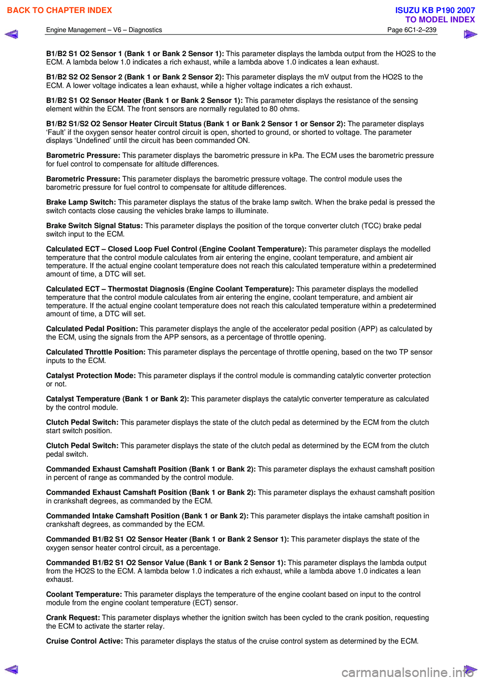
B1/B2 S1 O2 Sensor 1 (Bank 1 or Bank 2 Sensor 1): This parameter displays the lambda output from the HO2S to the
ECM. A lambda below 1.0 indicates a rich exhaust, while a lambda above 1.0 indicates a lean exhaust.
B1/B2 S2 O2 Sensor 2 (Bank 1 or Bank 2 Sensor 2): This parameter displays the mV output from the HO2S to the
ECM. A lower voltage indicates a lean exhaust, while a higher voltage indicates a rich exhaust.
B1/B2 S1 O2 Sensor Heater (Bank 1 or Bank 2 Sensor 1): This parameter displays the resistance of the sensing
element within the ECM. The front sensors are normally regulated to 80 ohms.
B1/B2 S1/S2 O2 Sensor Heater Circuit Status (Bank 1 or Bank 2 Sensor 1 or Sensor 2): The parameter displays
‘Fault’ if the oxygen sensor heater control circuit is open, shorted to ground, or shorted to voltage. The parameter
displays ‘Undefined’ until the circuit has been commanded ON.
Barometric Pressure: This parameter displays the barometric pressure in kPa. The ECM uses the barometric pressure
for fuel control to compensate for altitude differences.
Barometric Pressure: This parameter displays the barometric pressure voltage. The control module uses the
barometric pressure for fuel control to compensate for altitude differences.
Brake Lamp Switch: This parameter displays the status of the brake lamp switch. W hen the brake pedal is pressed the
switch contacts close causing the vehicles brake lamps to illuminate.
Brake Switch Signal Status: This parameter displays the position of the torque converter clutch (TCC) brake pedal
switch input to the ECM.
Calculated ECT – Closed Loop Fuel Control (Engine Coolant Temperature): This parameter displays the modelled
temperature that the control module calculates from air entering the engine, coolant temperature, and ambient air
temperature. If the actual engine coolant temperature does not reach this calculated temperature within a predetermined
amount of time, a DTC will set.
Calculated ECT – Thermostat Diagnosis (Engine Coolant Temperature): This parameter displays the modelled
temperature that the control module calculates from air entering the engine, coolant temperature, and ambient air
temperature. If the actual engine coolant temperature does not reach this calculated temperature within a predetermined
amount of time, a DTC will set.
Calculated Pedal Position: This parameter displays the angle of the accelerator pedal position (APP) as calculated by
the ECM, using the signals from the APP sensors, as a percentage of throttle opening.
Calculated Throttle Position: This parameter displays the percentage of throttle opening, based on the two TP sensor
inputs to the ECM.
Catalyst Protection Mode: This parameter displays if the control module is commanding catalytic converter protection
or not.
Catalyst Temperature (Bank 1 or Bank 2): This parameter displays the catalytic converter temperature as calculated
by the control module.
Clutch Pedal Switch: This parameter displays the state of the clutch pedal as determined by the ECM from the clutch
start switch position.
Clutch Pedal Switch: This parameter displays the state of the clutch pedal as determined by the ECM from the clutch
pedal switch.
Commanded Exhaust Camshaft Position (Bank 1 or Bank 2): This parameter displays the exhaust camshaft position
in percent of range as commanded by the control module.
Commanded Exhaust Camshaft Position (Bank 1 or Bank 2): This parameter displays the exhaust camshaft position
in crankshaft degrees, as commanded by the ECM.
Commanded Intake Camshaft Position (Bank 1 or Bank 2): This parameter displays the intake camshaft position in
crankshaft degrees, as commanded by the ECM.
Commanded B1/B2 S1 O2 Sensor Heater (Bank 1 or Bank 2 Sensor 1): This parameter displays the state of the
oxygen sensor heater control circuit, as a percentage.
Commanded B1/B2 S1 O2 Sensor Value (Bank 1 or Bank 2 Sensor 1): This parameter displays the lambda output
from the HO2S to the ECM. A lambda below 1.0 indicates a rich exhaust, while a lambda above 1.0 indicates a lean
exhaust.
Coolant Temperature: This parameter displays the temperature of the engine coolant based on input to the control
module from the engine coolant temperature (ECT) sensor.
Crank Request: This parameter displays whether the ignition switch has been cycled to the crank position, requesting
the ECM to activate the starter relay.
Cruise Control Active: This parameter displays the status of the cruise control system as determined by the ECM.
BACK TO CHAPTER INDEX
TO MODEL INDEX
ISUZU KB P190 2007
Page 3519 of 6020
Engine Management – V6 – Diagnostics Page 6C1-2–241
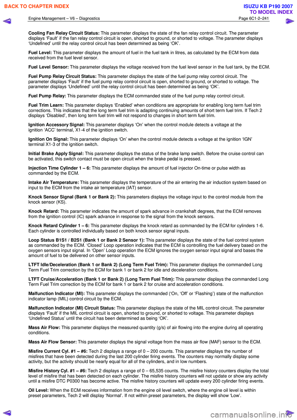
Cooling Fan Relay Circuit Status: This parameter displays the state of the fan relay control circuit. The parameter
displays ‘Fault’ if the fan relay control circuit is open, shorted to ground, or shorted to voltage. The parameter displays
‘Undefined’ until the relay control circuit has been determined as being ‘OK’.
Fuel Level: This parameter displays the amount of fuel in the fuel tank in litres, as calculated by the ECM from data
received from the fuel level sensor.
Fuel Level Sensor: This parameter displays the voltage received from the fuel level sensor in the fuel tank, by the ECM.
Fuel Pump Relay Circuit Status: This parameter displays the state of the fuel pump relay control circuit. The
parameter displays ‘Fault’ if the fuel pump relay control circuit is open, shorted to ground, or shorted to voltage. The
parameter displays ‘Undefined’ until the relay control circuit has been determined as being ‘OK’.
Fuel Pump Relay: This parameter displays the ECM commanded state of the fuel pump relay control circuit.
Fuel Trim Learn: This parameter displays ‘Enabled’ when conditions are appropriate for enabling long term fuel trim
corrections. This indicates that the long term fuel trim is adapting continuing amounts of short term fuel trim. If Tech 2
displays ‘Disabled’, then long term fuel trim will not respond to changes in short term fuel trim.
Ignition Accessory Signal: This parameter displays ‘On’ when the control module detects a voltage at the
ignition ‘ACC’ terminal, X1-4 of the ignition switch.
Ignition On Signal: This parameter displays ‘On’ when the control module detects a voltage at the ignition ‘IGN’
terminal X1-3 of the ignition switch.
Initial Brake Apply Signal: This parameter displays the status of the brake lamp switch. Before the cruise control can
be activated, this switch contact must be open circuit when the brake pedal is pressed.
Injection Time Cylinder 1 – 6: This parameter displays the amount of fuel injector On-time or pulse width as
commanded by the ECM.
Intake Air Temperature: This parameter displays the temperature of the air entering the air induction system based on
input to the ECM from the intake air temperature (IAT) sensor.
Knock Sensor Signal (Bank 1 or Bank 2): This parameters displays the voltage input to the control module from the
knock sensor (KS).
Knock Retard: This parameter indicates the amount of spark advance in crankshaft degrees, that the ECM removes
from the ignition control (IC) spark advance in response to the signal from the knock sensors.
Knock Retard Cylinder 1 – 6: This parameter displays the knock retard as commanded by the ECM for cylinders 1-6.
Each cylinder is controlled individually based on both knock sensor signal inputs.
Loop Status B1S1 / B2S1 (Bank 1 or Bank 2 Sensor 1): This parameter displays the state of the fuel control system
as commanded by the ECM. ‘Closed’ Loop operation indicates that the ECM is controlling the fuel delivery based on the
oxygen sensors input signal. In ‘Open’ Loop operation the ECM ignores the oxygen sensor input signal and bases the
amount of fuel to be delivered on other sensor inputs.
LTFT Idle/Deceleration (Bank 1 or Bank 2) (Long Term Fuel Trim): This parameter displays the commanded Long
Term Fuel Trim correction by the ECM for bank 1 or bank 2 for idle and deceleration conditions.
LTFT Cruise/Acceleration (Bank 1 or Bank 2) (Long Term Fuel Trim): This parameter displays the commanded Long
Term Fuel Trim correction by the ECM for bank 1 or bank 2 for cruise and acceleration conditions.
Malfunction Indicator (MI): This parameter displays the commanded (‘On, ‘Off’ or ‘Flashing’) state of the malfunction
indicator lamp (MIL) control circuit by the ECM.
Malfunction Indicator (MI) Circuit Status: This parameter displays the state of the MIL control circuit. The parameter
displays ‘Fault’ if the MIL control circuit is open, shorted to ground, or shorted to voltage. This parameter displays
‘Undefined Status’ until the circuit has been determined as being ‘OK’.
Mass Air Flow: This parameter displays the measured quantity (g/s) of air flowing into the engine during all operating
conditions.
Mass Air Flow Sensor: This parameter displays the signal voltage from the mass air flow (MAF) sensor to the ECM.
Misfire Current Cyl. #1 – #6: Tech 2 displays a range of 0 – 200 counts. This parameter displays the number of
misfires that have been detected during the last 200 cylinder firing events. The counters may normally display some
activity, but the activity should be nearly equal for all of the cylinders, and in low numbers.
Misfire History Cyl. #1 – #6: Tech 2 displays a range of 0 – 65,535 counts. The misfire history counters display the total
level of misfire that has been detected on each cylinder. The misfire history counters will not update or show any activity
until a misfire DTC P0300 has become active. The misfire history counters will update every 200 cylinder firing events.
Oil Level: W hen the ECM receives information from the engine oil level switch, where the engine oil level is within
preset parameters, Tech 2 will display ‘Normal’. If not within preset parameters, the display will show ‘Low’.
BACK TO CHAPTER INDEX
TO MODEL INDEX
ISUZU KB P190 2007
Page 3523 of 6020
Engine Management – V6 – Diagnostics Page 6C1-2–245
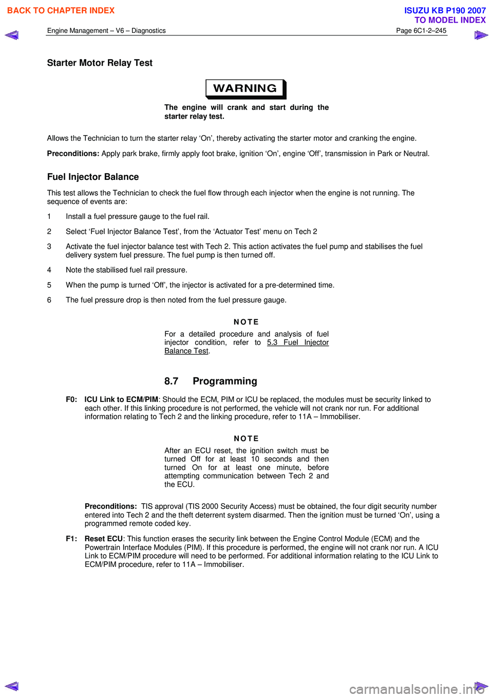
Starter Motor Relay Test
The engine will crank and start during the
starter relay test.
Allows the Technician to turn the starter relay ‘On’, thereby activating the starter motor and cranking the engine.
Preconditions: Apply park brake, firmly apply foot brake, ignition ‘On’, engine ‘Off’, transmission in Park or Neutral.
Fuel Injector Balance
This test allows the Technician to check the fuel flow through each injector when the engine is not running. The
sequence of events are:
1 Install a fuel pressure gauge to the fuel rail.
2 Select ‘Fuel Injector Balance Test’, from the ‘Actuator Test’ menu on Tech 2
3 Activate the fuel injector balance test with Tech 2. This action activates the fuel pump and stabilises the fuel delivery system fuel pressure. The fuel pump is then turned off.
4 Note the stabilised fuel rail pressure.
5 W hen the pump is turned ‘Off’, the injector is activated for a pre-determined time.
6 The fuel pressure drop is then noted from the fuel pressure gauge.
NOTE
For a detailed procedure and analysis of fuel
injector condition, refer to 5.3 Fuel Injector
Balance Test.
8.7 Programming
F0: ICU Link to ECM/PIM : Should the ECM, PIM or ICU be replaced, the modules must be security linked to
each other. If this linking procedure is not performed, the vehicle will not crank nor run. For additional
information relating to Tech 2 and the linking procedure, refer to 11A – Immobiliser.
NOTE
After an ECU reset, the ignition switch must be
turned Off for at least 10 seconds and then
turned On for at least one minute, before
attempting communication between Tech 2 and
the ECU.
Preconditions: TIS approval (TIS 2000 Security Access) must be obtained, the four digit security number
entered into Tech 2 and the theft deterrent system disarmed. Then the ignition must be turned ‘On’, using a
programmed remote coded key.
F1: Reset ECU : This function erases the security link between the Engine Control Module (ECM) and the
Powertrain Interface Modules (PIM). If this procedure is performed, the engine will not crank nor run. A ICU
Link to ECM/PIM procedure will need to be performed. For additional information relating to the ICU Link to
ECM/PIM procedure, refer to 11A – Immobiliser.
BACK TO CHAPTER INDEX
TO MODEL INDEX
ISUZU KB P190 2007
Page 3530 of 6020
Engine Management – V6 – Service Operations Page 6C1-3–6
Basic Diagnostic Tools Required
Use of incorrect electrical circuit diagnostic
tools when performing certain service
procedures could result in incorrect
diagnostic results or damage to components.
The following electrical circuit testing tools are required to perform the diagnostic procedures detailed in this Section:
• Test lamp, refer to 8A Electrical – Body and Chassis for further information.
• Digital multimeter with 10 M Ω ohms impedance, refer to 8A Electrical – Body and Chassis for further information.
• Connector test adapter kit Tool No. J35616-A.
1.3 Service Operations Not Covered In This
Section
There are situations where components and/or procedures related to the powertrain management system are covered in
other Sections of the service documentation. To aid technicians in locating the necessary service procedures for these
components and/or procedures, refer to the stated references.
Air-conditioning System
For A/C pressure switch replacement procedure, refer to 2A Heater and Air-conditioning.
Electrical Components
For the following electrical system component replacement procedures, refer to the appropriate Sections as follows:
• Extended brake pedal travel switch and stop lamp switch service operations, refer to 5C Brakes.
• Fuse and relay locations, refer to 8A Electrical-Body and Chassis.
• Cruise control switch assembly service operations, refer to 8C Cruise Control – HFV6.
• Powertrain interface module PIM removal and installation procedure, refer to 6E1 Powertrain Interface Module – V6.
• Neutral start and back-up lamp switch, refer to 7C4 Automatic Transmission – 4L60E – On-vehicle Servicing.
• Vehicle speed sensor service operations, refer to:
− 7C4 Automatic Transmission – 4L60E – On-vehicle Servicing
− 7B1 Manual Transmission – V6
Fuel System
For the following fuel system component replacement procedures, refer to 6C Fuel System – V6.
• Fuel system cleaning,
• Fuel system leak and pressure test,
• Fuel feed hose to fuel rail replacement,
• Fuel line quick connect fittings,
• Evaporative emission control canister,
• Fuel filter,
• Fuel hose / pipes layout,
• Fuel pump motor assembly and fuel pressure regulator assembly,
• Fuel sender assembly service operations.
BACK TO CHAPTER INDEX
TO MODEL INDEX
ISUZU KB P190 2007
Page 3624 of 6020
Starting System – V6 Page 6D1-2–16
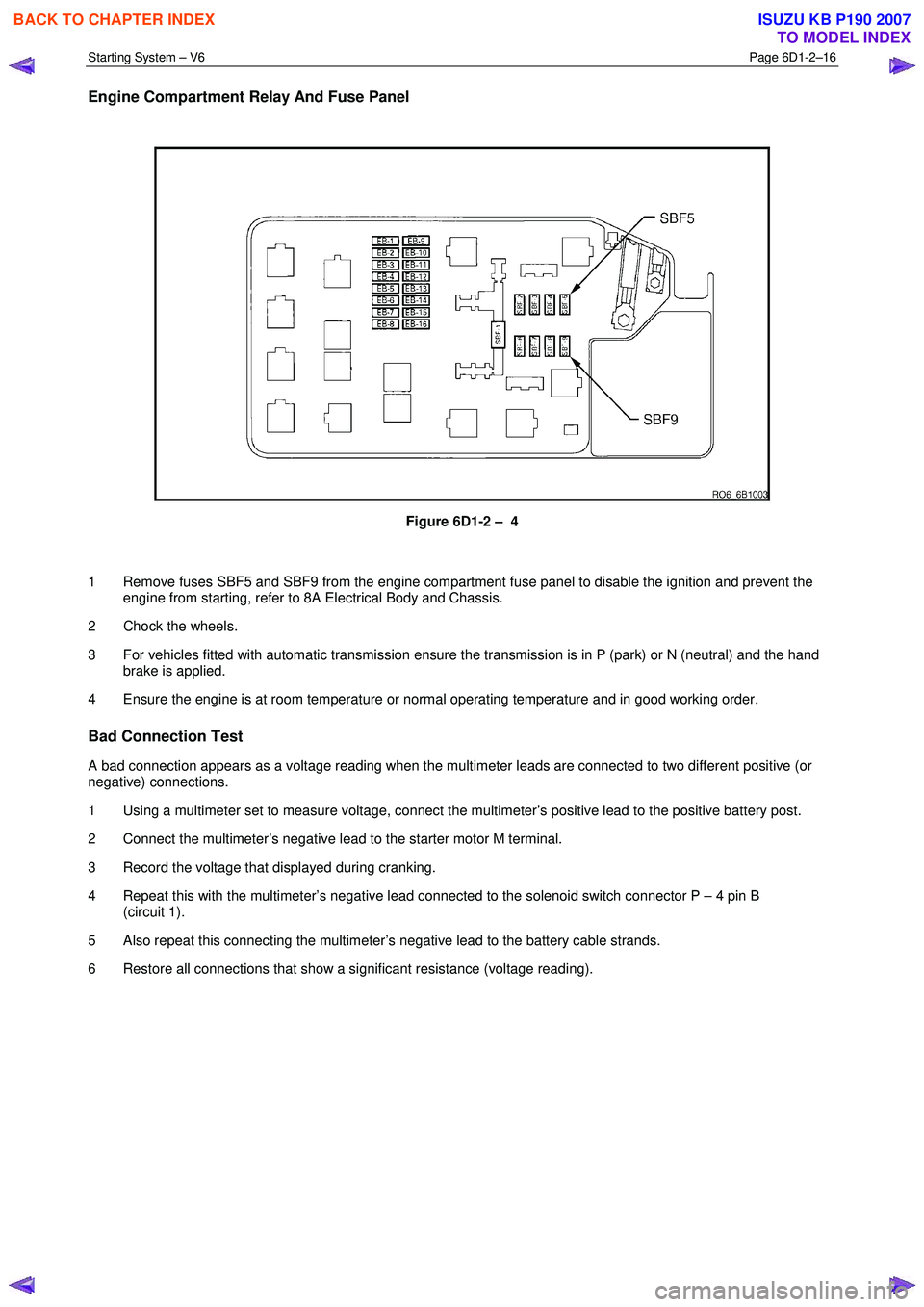
Engine Compartment Relay And Fuse Panel
Figure 6D1-2 – 4
1 Remove fuses SBF5 and SBF9 from the engine compartment fuse panel to disable the ignition and prevent the engine from starting, refer to 8A Electrical Body and Chassis.
2 Chock the wheels.
3 For vehicles fitted with automatic transmission ensure the transmission is in P (park) or N (neutral) and the hand brake is applied.
4 Ensure the engine is at room temperature or normal operating temperature and in good working order.
Bad Connection Test
A bad connection appears as a voltage reading when the multimeter leads are connected to two different positive (or
negative) connections.
1 Using a multimeter set to measure voltage, connect the multimeter’s positive lead to the positive battery post.
2 Connect the multimeter’s negative lead to the starter motor M terminal.
3 Record the voltage that displayed during cranking.
4 Repeat this with the multimeter’s negative lead connected to the solenoid switch connector P – 4 pin B (circuit 1).
5 Also repeat this connecting the multimeter’s negative lead to the battery cable strands.
6 Restore all connections that show a significant resistance (voltage reading).
BACK TO CHAPTER INDEX
TO MODEL INDEX
ISUZU KB P190 2007
Page 3656 of 6020
Battery Page 6D1-3–16
NOTE
Charging a battery at higher current rates can
significantly reduce the life of the battery.
Charge Rate Initial Current Maximum Time Required
Slow charge 4 A 24 hours
Fast charge 35 A 2 hours
6 After a few minutes, check the colour and specific gravity of the electrolyte. Refer to 3.3 Hydrometer Test.
7 Monitor the electrolyte temperature while the battery is charging. If the electrolyte temperature reaches 55 °C:
a switch the charging current off,
b allow the battery to cool,
c reduce the charging current, and
d restart charging the battery.
NOTE
For the best results, charge the battery with the
electrolyte and plates at room temperature. An
extremely cold battery may not appear to accept
current for several hours after starting the battery
charger. If the battery does not appear to accept
charge after several hours replace the battery.
8 For slow charging check the voltage and specific gravity each hour or more regularly for fast charging. Stop the charging when there is no change in voltage or electrolyte specific gravity over three checks.
9 If the battery was fast charged connect the battery to a slow-charger for a few hours to bring the battery to the fully charged condition. Ensure the last few hours of charge do not exceed 1 A.
10 Tighten the filler caps. Ensure they are secure.
11 Install the battery in the vehicle. Refer to 4.1 Battery.
4.3 Emergency Jump Starting Procedure
Safety Precautions
• Read and obey the general safety precautions for working with batteries, refer to 2 Safety Precautions.
• Do not allow the vehicles to touch each other during the jump starting procedure.
• Ensure the assisting vehicle battery has the same voltage rating and connects negative to ground. If this is not the
case, serious injury and damage to electrical equipment can result.
• Do not push or tow the vehicle to start it. Damage can result when unburnt fuel reaches the catalytic converter and
ignites.
• Do not start the vehicle using a fast charger.
• W hen using jumper leads, treat both the booster battery and the discharged battery with care.
• Do not allow sparks, flame or smoking near the battery.
• Ensure that metal tools or jumper cables do not simultaneously contact the battery positive terminal and any other
metal part of the vehicle.
Jump Starting Procedure
1 Position the assisting vehicle so the batteries of both vehicles are close together, refer to Figure 6D1-3 – 10.
2 Apply the park brake on both vehicles.
3 Ensure that P (park) is selected for automatic transmission and N (neutral) is selected for manual transmissions.
BACK TO CHAPTER INDEX
TO MODEL INDEX
ISUZU KB P190 2007
Page 3771 of 6020
Automatic Transmission – 4L60E – General Information Page 7C1–11
4 Transmission Definitions and
Abbreviations
The following definitions and abbreviations are provided to establish a common language and assist the user in
describing transmission related conditions. The use of these terms and/or conditions can be found in the various parts of
the automatic transmission sections, but more particularly in 7C3 Automatic Transmission – 4L60E – Hydraulic and
Mechanical Diagnosis.
4.1 Throttle Position Related Definitions
Throttle Position Definition
Minimum Throttle The least amount of throttle opening required for an upshift.
Light Throttle Approximately 1/4 of accelerator pedal travel (25% Throttle Position).
Medium Throttle Approximately 1/2 of accelerator pedal travel (50% Throttle Position).
Heavy Throttle Approximately 3/4 of accelerator pedal travel (75% Throttle Position).
Wide Open Throttle (WOT) Full travel of the accelerator pedal (100% Throttle Position).
Full Throttle Detent Downshift A quick apply of the accelerator pedal to its full travel, forcing a downshift.
Zero Throttle Coast Down A full release of the accelerator pedal while the car is in motion and in drive range.
Engine Braking A condition where the engine is used to slow the car by manually downshifting
during a zero throttle coast down.
4.2 Noise Condition Related Definitions
Noise Condition Definition
Planetary Gear Noise A whine related to car speed most noticeable in first gear or reverse. Becomes less
noticeable after an upshift.
Pump Noise A high pitch whine increasing with engine r.p.m.
4.3 General Definitions
General Definition
Accumulator A component of the transmission that absorbs hydraulic pressure during the apply of a
clutch or band. Accumulators are designed to control the quality of a shift from one gear range to another.
Adaptive Learning Programming within the TCM that automatically adjusts hydraulic pressures in order to compensate for changes in the transmission (i.e. component wear).
Applied An 'Applied Component' is holding another component to which it is splined or
assembled to. Also referred to as "engaged".
Apply Components Hydraulically operated clutches, servo’s, bands and mechanical one-way roller or
sprag clutches that drive or hold members of a planetary gear set.
Apply Plate A steel clutch plate in a clutch pack, located next to the (apply) piston.
Backing Plate A steel plate in a clutch pack that is usually the last plate in that clutch assembly
(furthest from the clutch piston).
Band An apply component that consists of a flexible strip of steel and friction material that
wraps around a drum. When applied, it tightens around the drum and prevents the drum from rotating.
Brake Switch An electrical device that provides signals to the transmission control module (TCM),
based on the position of the brake pedal. The TCM uses this information to apply or
release the torque converter clutch (TCC).
Centrifugal Force A force that is imparted on an object (due to rotation) that increases as that object moves further away from a centre-point of rotation.
BACK TO CHAPTER INDEX
TO MODEL INDEX
ISUZU KB P190 2007