Page 2845 of 6020

Engine Mechanical – V6 Page 6A1–68
Page 6A1–68
Pressure Check
1 Run the engine to bring it to normal operating temperature.
2 Park the vehicle on a level surface. A vehicle not level will affect the accuracy of the level reading.
3 Stop the engine and wait 5 to 10 minutes to a llow the oil to drain back into the oil pan.
4 Check the oil level and top up with the recommended engine o il as required, refer to Check, in this Section.
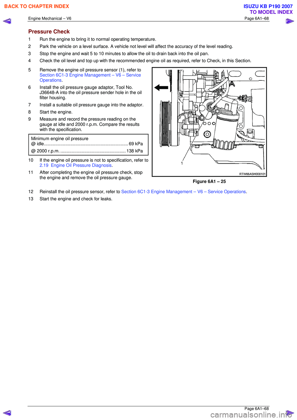
5 Remove the engine oil pressure sensor (1), refer to Section 6C1-3 Engine Management – V6 – Service
Operations .
6 Install the oil pressure gauge adaptor, Tool No. J36648-A into the oil pressure sender hole in the oil
filter housing.
7 Install a suitable oil pressure gauge into the adaptor.
8 Start the engine.
9 Measure and record the pressure reading on the gauge at idle and 2000 r.p.m. Compare the results
with the specification.
Minimum engine oil pressure
@ idle ................................................................... 69 kPa
@ 2000 r.p.m. .................................................... 138 kPa
10 If the engine oil pressure is not to specification, refer to
2.19 Engine Oil Pressure Diagnosis .
11 After completing the engine oil pressure check, stop the engine and remove the oil pressure gauge.
Figure 6A1 – 25
12 Reinstall the oil pressure sensor, refer to Section 6C1-3 Engine Management – V6 – Service Operations.
13 Start the engine and check for leaks.
BACK TO CHAPTER INDEX
TO MODEL INDEX
ISUZU KB P190 2007
Page 2846 of 6020
Engine Mechanical – V6 Page 6A1–69
Page 6A1–69
3.2 Oil Filter Cartridge
Replace
NOTE
• The oil filter cartri dge should be replaced at
the correct time or distance intervals, refer to
Section 0B Lubrication and Service .
• The oil filter cartridge should also be replaced
whenever the engine oil is suspected to have
been contaminated by foreign material.
1 Remove and discard the oil filter cartridge (1).
2 Install the new o il filter cartridge.
Figure 6A1 – 26
BACK TO CHAPTER INDEX
TO MODEL INDEX
ISUZU KB P190 2007
Page 2849 of 6020
Engine Mechanical – V6 Page 6A1–72
Page 6A1–72
3.5 Accessory Drive Belt
RWD Vehicle
Remove
1 Remove the air intake duct from between the air flow meter and the throttle body, refer to
Section 6C1-3 Engine Management – V6 – Service Operations.
2 Note the accessory drive belt (1) routing.
Figure 6A1 – 29
3 Using a suitable ½” drive socket bar (1), rotate the drive belt tensioner (2) clockwise, to reduce belt
tension.
4 While holding the tensioner in the reduced tension
position, remove the accessory drive belt (3).
NOTE
If required use an assistant to maintain the tensioner in the required position.
CAUTION
If running the engine with the accessory
drive belt removed, the coolant pump will
not be operating and the engine may
overheat if left unsupervised even for a short
period.
Figure 6A1 – 30
BACK TO CHAPTER INDEX
TO MODEL INDEX
ISUZU KB P190 2007
Page 2850 of 6020
Engine Mechanical – V6 Page 6A1–73
Page 6A1–73
Reinstall
1 Install the drive belt over the A/C compressor, idler pulley, power steering pump, coolant pump, generator and
tensioner pulleys.
2 Using a suitable ½” drive socket bar (1), rotate the driv e belt tensioner (2) clockwise, refer to Figure 6A1 – 30.
3 With an assistant holding the tensi oner in the required position, feed the accessory drive belt (3) over the
crankshaft pulley.
4 Slowly release the drive belt tensioner mechanism.
NOTE
Ensure the drive belt ribs are correctly aligned
with the grooves in the accessory drive pulleys or
damage to the drive belt and accessory drive
components and pulleys may occur.
5 Reinstall the air intake duct to the ai r flow meter and the throttle body, refer to Section 6C1-3 Engine Management
– V6 – Service Operations .
6 Run the engine to ensure correct operation.
BACK TO CHAPTER INDEX
TO MODEL INDEX
ISUZU KB P190 2007
Page 2852 of 6020
Engine Mechanical – V6 Page 6A1–75
Page 6A1–75
3.7 Accessory Drive Belt Tensioner
Assembly
Remove
1 Remove the accessory drive belt, refer to 3.5 Accessory Drive Belt.
2 Remove the three bolts (2) attaching accessory drive belt tensioner assembly (1).
3 Remove the accessory drive belt tensioner assembly.
NOTE
The accessory drive belt tensioner pulley is not
serviced separately. If the pulley is found to be
faulty, the entire tensi oner assembly must be
replaced.
Repairing a damaged accessory drive belt
pulley should not be attempted under any
circumstances.
Figure 6A1 – 32
Reinstall
Reinstallation of the accessory drive belt tensioner assembly is the reverse of the removal procedure. Tighten the bolts to
the correct torque specification.
Accessory drive belt tensioner
attaching bolt torque specification ......................50.0 Nm
BACK TO CHAPTER INDEX
TO MODEL INDEX
ISUZU KB P190 2007
Page 2854 of 6020
Engine Mechanical – V6 Page 6A1–77
Page 6A1–77
3.9 Upper Intake Manifold
The intake manifold comprises of an upper and lower section. Some service procedures only require the removal of the
upper intake manifold (e.g. fuel injector/spark plug servicing), while other servic e procedures require the removal of both
the upper and lower manifold as a complete assembly (e .g. cylinder head/s). If the complete assembly needs to be
removed, refer to 3.10 Intake Manifold Assembly – Complete .
Remove
Disconnection of the battery affects
certain vehicle electronic systems. Refer to
1.1 WARNING, CAUTION and NOTES before
disconnecting the battery.
1 Disconnect the battery negative terminal.
2 Remove the air intake duct (1) and hose (2), refer to
Section 6C1-3 Engine Management – V6 – Service
Operations .
Figure 6A1 – 34
BACK TO CHAPTER INDEX
TO MODEL INDEX
ISUZU KB P190 2007
Page 2857 of 6020

Engine Mechanical – V6 Page 6A1–80
Page 6A1–80
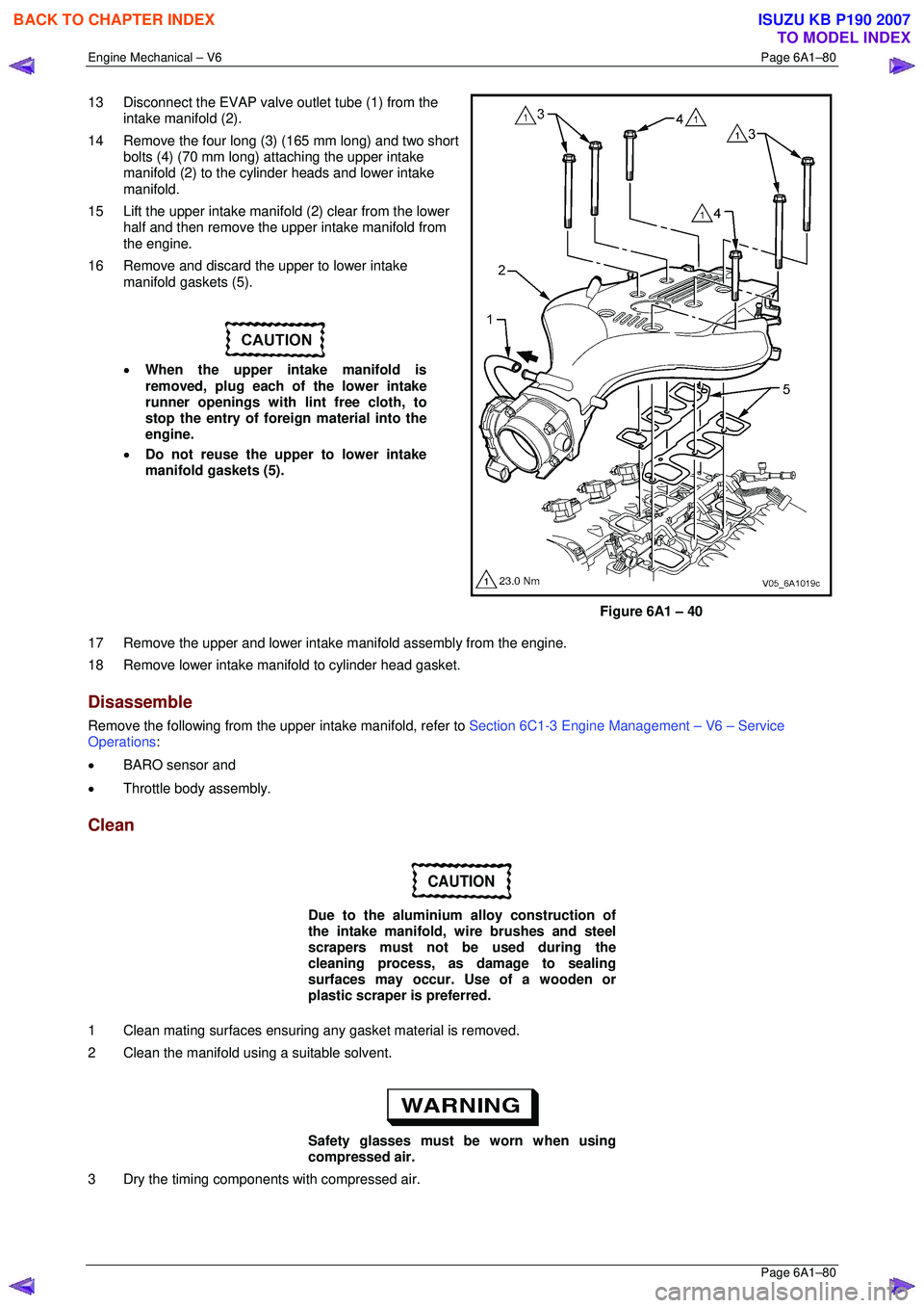
13 Disconnect the EVAP valve outlet tube (1) from the
intake manifold (2).
14 Remove the four long (3) (165 mm long) and two short bolts (4) (70 mm long) attaching the upper intake
manifold (2) to the cylinder heads and lower intake
manifold.
15 Lift the upper intake manifold (2) clear from the lower half and then remove the upper intake manifold from
the engine.
16 Remove and discard the upper to lower intake manifold gaskets (5).
• When the upper intake manifold is
removed, plug each of the lower intake
runner openings with lint free cloth, to
stop the entry of forei gn material into the
engine.
• Do not reuse the upper to lower intake
manifold gaskets (5).
Figure 6A1 – 40
17 Remove the upper and lower intake manifold assembly from the engine.
18 Remove lower intake mani fold to cylinder head gasket.
Disassemble
Remove the following from the upper intake manifold, refer to Section 6C1-3 Engine Management – V6 – Service
Operations :
• BARO sensor and
• Throttle body assembly.
Clean
CAUTION
Due to the aluminium alloy construction of
the intake manifold, wire brushes and steel
scrapers must not be used during the
cleaning process, as damage to sealing
surfaces may occur. Use of a wooden or
plastic scraper is preferred.
1 Clean mating surfaces ensuring any gasket material is removed.
2 Clean the manifold using a suitable solvent.
Safety glasses must be worn when using
compressed air.
3 Dry the timing components with compressed air.
BACK TO CHAPTER INDEX
TO MODEL INDEX
ISUZU KB P190 2007
Page 2860 of 6020
Engine Mechanical – V6 Page 6A1–83
Page 6A1–83
3.10 Intake Manifold Assembly – Complete
The intake manifold comprises of an upper and lower section. Some service procedures only require the removal of the
upper intake manifold (e.g. fuel injector/spark plug servicing), while other servic e procedures require the removal of both
the upper and lower manifold as a complete assembly (e.g . cylinder head/s). If only the upper intake manifold needs to
be removed, refer to 3.9 Upper Intake Manifold .
Remove
Disconnection of the battery affects
certain vehicle electronic systems. Refer to
1.1 WARNING, CAUTION and NOTES before
disconnecting the battery.
1 Depressurise the fuel system.
2 Disconnect the battery negative terminal.
3 Remove the air intake duc t (1) and hose (2), refer to
Section 6C1-3 Engine Management – V6 – Service
Operations .
Figure 6A1 – 43
BACK TO CHAPTER INDEX
TO MODEL INDEX
ISUZU KB P190 2007