2007 ISUZU KB P190 service
[x] Cancel search: servicePage 2719 of 6020
Engine Mechanical – V6 Page 6A1–240
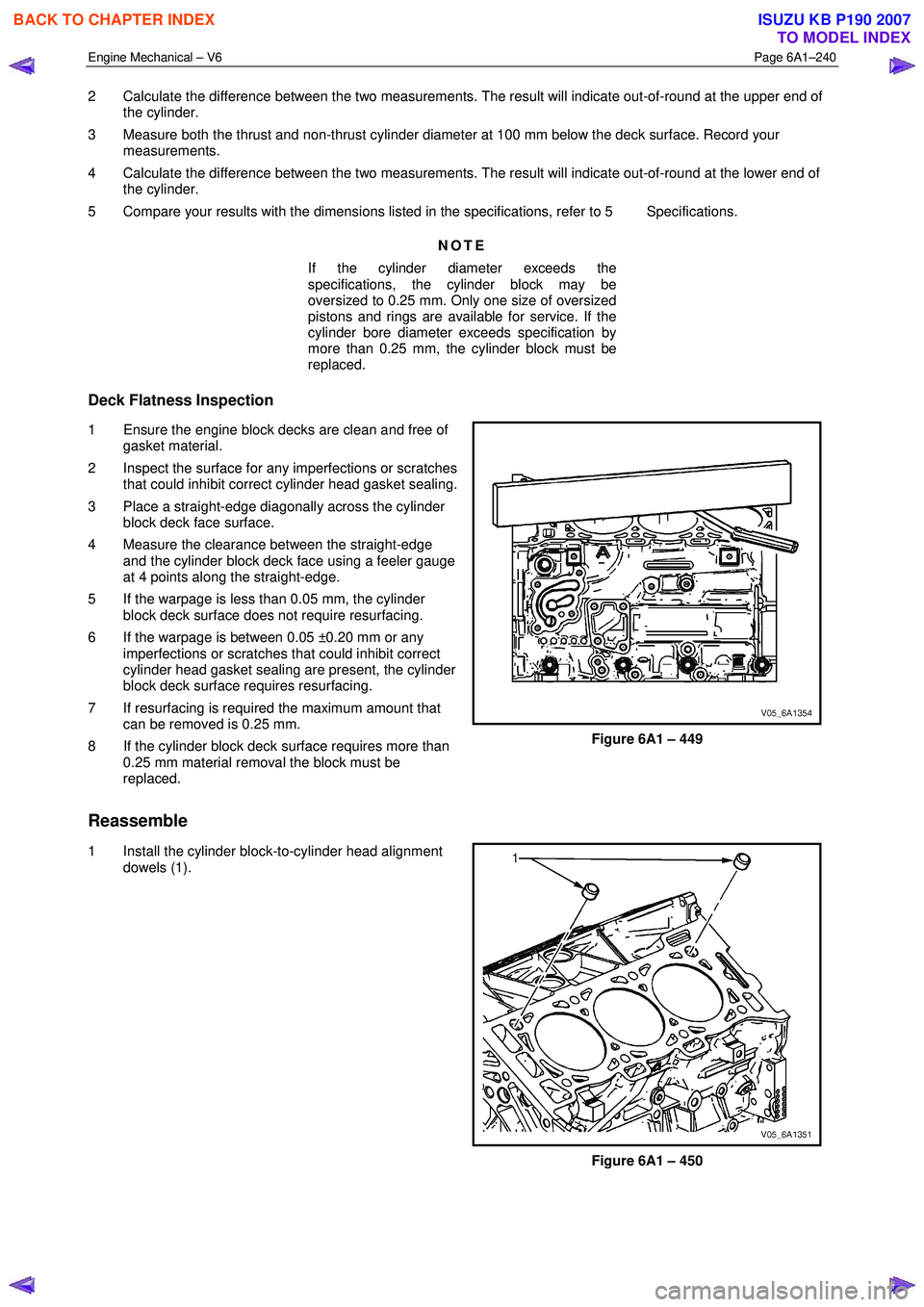
2 Calculate the difference between the two measurements. The result will indicate out-of-round at the upper end of
the cylinder.
3 Measure both the thrust and non-thrust cylinder diameter at 100 mm below the deck surface. Record your measurements.
4 Calculate the difference between the two measurements. The result will indicate out-of-round at the lower end of the cylinder.
5 Compare your results with the dimensions listed in the specifications, refer to 5 Specifications.
NOTE
If the cylinder diameter exceeds the
specifications, the cylinder block may be
oversized to 0.25 mm. Only one size of oversized
pistons and rings are available for service. If the
cylinder bore diameter exceeds specification by
more than 0.25 mm, the cylinder block must be
replaced.
Deck Flatness Inspection
1 Ensure the engine block decks are clean and free of gasket material.
2 Inspect the surface for any imperfections or scratches that could inhibit correct cylinder head gasket sealing.
3 Place a straight-edge diagonally across the cylinder block deck face surface.
4 Measure the clearance between the straight-edge and the cylinder block deck face using a feeler gauge
at 4 points along the straight-edge.
5 If the warpage is less than 0.05 mm, the cylinder block deck surface does not require resurfacing.
6 If the warpage is between 0.05 ±0.20 mm or any imperfections or scratches that could inhibit correct
cylinder head gasket sealing are present, the cylinder
block deck surface requires resurfacing.
7 If resurfacing is required the maximum amount that can be removed is 0.25 mm.
8 If the cylinder block deck surface requires more than 0.25 mm material removal the block must be
replaced.
Figure 6A1 – 449
Reassemble
1 Install the cylinder block-to-cylinder head alignment
dowels (1).
Figure 6A1 – 450
BACK TO CHAPTER INDEX
TO MODEL INDEX
ISUZU KB P190 2007
Page 2767 of 6020
Engine Mechanical – V6 Page 6A1–288
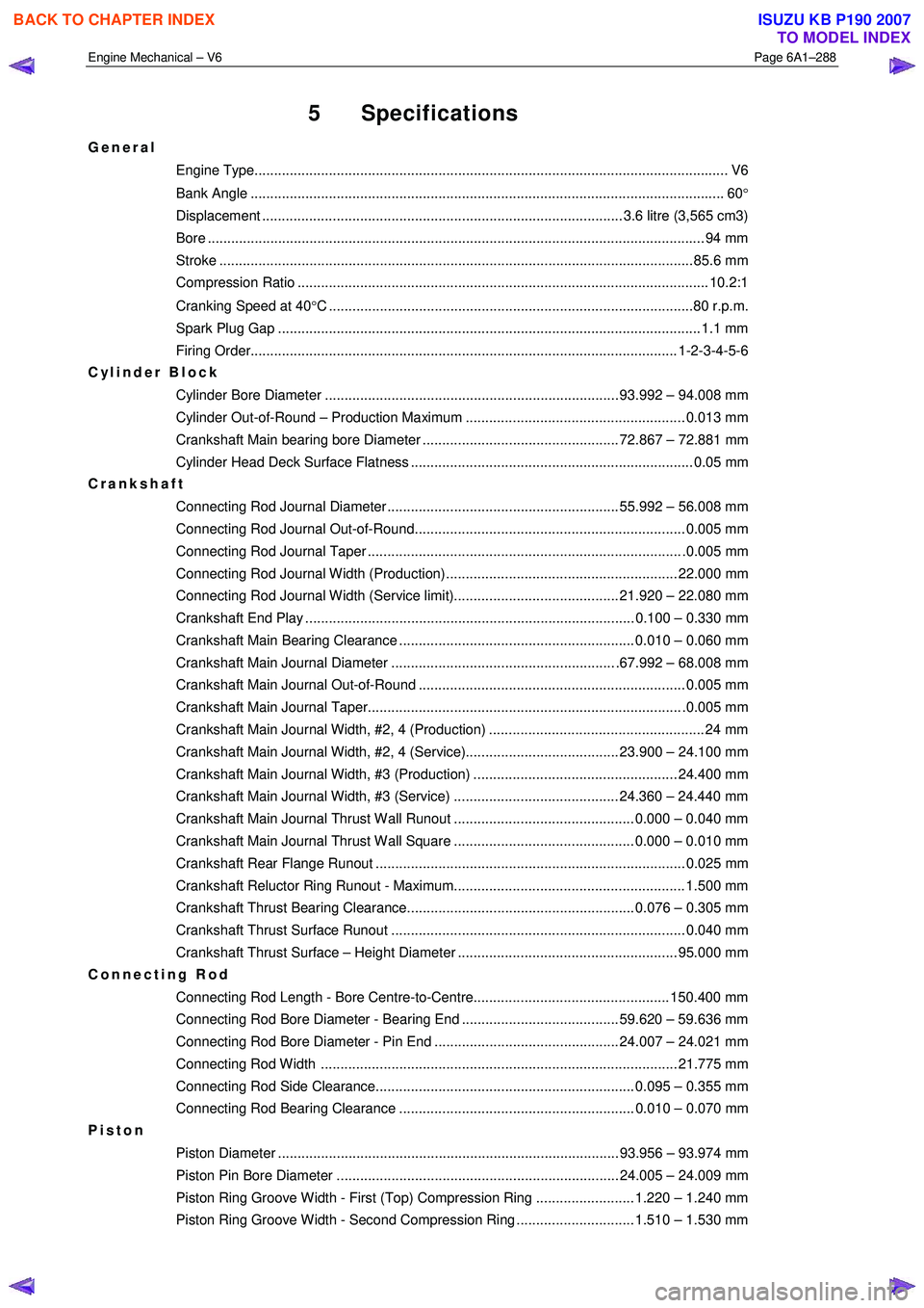
5 Specifications
General
Engine Type.................................................................................................................... ..... V6
Bank Angle ..................................................................................................................... .... 60°
Displacement ............................................................................................ 3.6 litre (3,565 cm3)
Bore ........................................................................................................................... .... 94 mm
Stroke ......................................................................................................................... 85.6 mm
Compression Ratio ......................................................................................................... 10.2: 1
Cranking Speed at 40 °C .............................................................................................80 r.p.m.
Spark Plug Gap ............................................................................................................ 1.1 m m
Firing Order............................................................................................................. 1-2-3- 4-5-6
Cylinder Block
Cylinder Bore Diameter ........................................................................... 93.992 – 94.008 mm
Cylinder Out-of-Round – Production Maximum ........................................................ 0.013 mm
Crankshaft Main bearing bore Diameter .................................................. 72.867 – 72.881 mm
Cylinder Head Deck Surface Flatness ........................................................................ 0.05 mm
Crankshaft
Connecting Rod Journal Diameter ........................................................... 55.992 – 56.008 mm
Connecting Rod Journal Out-of-Round..................................................................... 0.005 mm
Connecting Rod Journal Taper ................................................................................ .0.005 mm
Connecting Rod Journal Width (Production)........................................................... 22.000 mm
Connecting Rod Journal Width (Service limit).......................................... 21.920 – 22.080 mm
Crankshaft End Play .................................................................................... 0.100 – 0.330 mm
Crankshaft Main Bearing Clearance ............................................................ 0.010 – 0.060 mm
Crankshaft Main Journal Diameter ......................................................... .67.992 – 68.008 mm
Crankshaft Main Journal Out-of-Round .................................................................... 0.005 mm
Crankshaft Main Journal Taper................................................................................ .0.005 mm
Crankshaft Main Journal Width, #2, 4 (Production) ....................................................... 24 mm
Crankshaft Main Journal Width, #2, 4 (Service)....................................... 23.900 – 24.100 mm
Crankshaft Main Journal Width, #3 (Production) .................................................... 24.400 mm
Crankshaft Main Journal Width, #3 (Service) .......................................... 24.360 – 24.440 mm
Crankshaft Main Journal Thrust Wall Runout .............................................. 0.000 – 0.040 mm
Crankshaft Main Journal Thrust Wall Square .............................................. 0.000 – 0.010 mm
Crankshaft Rear Flange Runout ............................................................................... 0.025 mm
Crankshaft Reluctor Ring Runout - Maximum........................................................... 1.500 mm
Crankshaft Thrust Bearing Clearance.......................................................... 0.076 – 0.305 mm
Crankshaft Thrust Surface Runout ........................................................................... 0.040 mm
Crankshaft Thrust Surface – Height Diameter ........................................................ 95.000 mm
Connecting Rod
Connecting Rod Length - Bore Centre-to-Centre.................................................. 150.400 mm
Connecting Rod Bore Diameter - Bearing End ........................................ 59.620 – 59.636 mm
Connecting Rod Bore Diameter - Pin End ............................................... 24.007 – 24.021 mm
Connecting Rod Width ........................................................................................... 21.775 mm
Connecting Rod Side Clearance.................................................................. 0.095 – 0.355 mm
Connecting Rod Bearing Clearance ............................................................ 0.010 – 0.070 mm
Piston
Piston Diameter ....................................................................................... 93.956 – 93.974 mm
Piston Pin Bore Diameter ........................................................................ 24.005 – 24.009 mm
Piston Ring Groove Width - First (Top) Compression Ring ......................... 1.220 – 1.240 mm
Piston Ring Groove Width - Second Compression Ring .............................. 1.510 – 1.530 mm
BACK TO CHAPTER INDEX
TO MODEL INDEX
ISUZU KB P190 2007
Page 2778 of 6020
Engine Mechanical – V6 Page 6A1–1
Page 6A1–1
Section 6A1
Engine Mechanical – V6
ATTENTION
Before performing any service operation or other procedure described in this Section, refer to 1.1 WARNING,
CAUTION and NOTES for correct workshop practices with regard to safety and/or property damage.
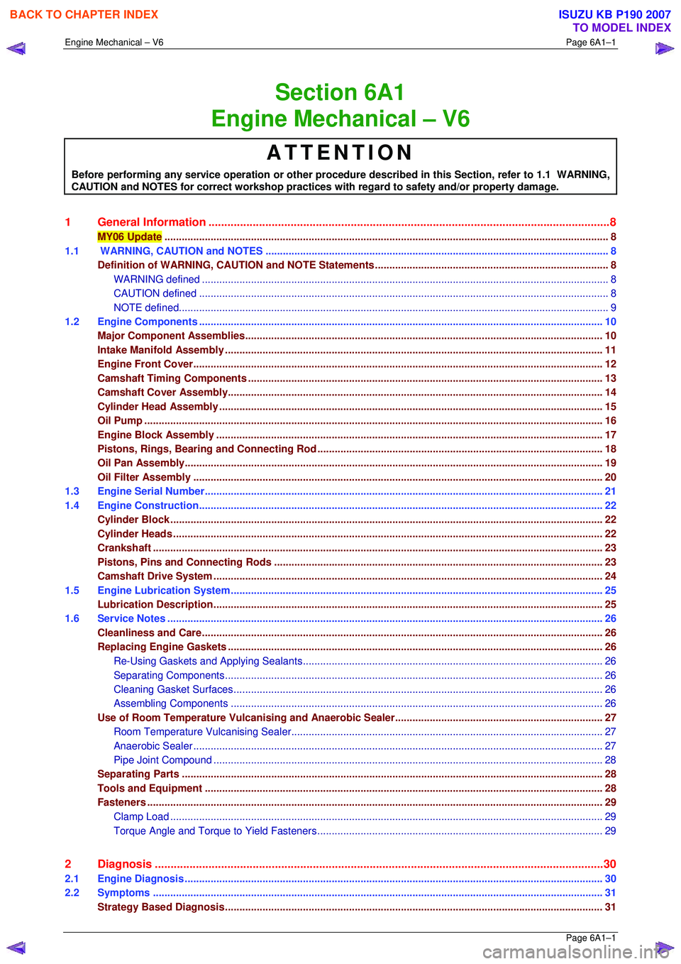
1 General Information ............................................................................................................ ...................8
MY06 Update .................................................................................................................... ......................................8
1.1 WARNING, CAUTION and NOTES .................................................................................................... ...................8
Definition of WARNING, CAUT ION and NOTE Statements ............................................................................. ....8
WARNING defined ................................................................................................................ .............................8
CAUTION defined ................................................................................................................ ..............................8
NOTE defined................................................................................................................... ..................................9
1.2 Engine Components .............................................................................................................. ..............................10
Major Component Assemblies............................................................................................................................ 10
Intake Manifold Assembly ....................................................................................................... ............................11
Engine Front Cover............................................................................................................. .................................12
Camshaft Timing Components ..................................................................................................... ......................13
Camshaft Cove r Assembly........................................................................................................ ..........................14
Cylinder Head Assembly ......................................................................................................... ............................15
Oil Pump ....................................................................................................................... ........................................16
Engine Block Assembly .......................................................................................................... ............................17
Pistons, Rings, Bearing and Connecting Rod ..................................................................................... ..............18
Oil Pan Assembly............................................................................................................... ..................................19
Oil Filter Assembly ............................................................................................................ ..................................20
1.3 Engine Serial Number........................................................................................................... ...............................21
1.4 Engine Construction............................................................................................................ ................................22
Cylinder Block ................................................................................................................. .....................................22
Cylinder Heads ..................................................................................................................................................... 22
Crankshaft ..................................................................................................................... .......................................23
Pistons, Pins and Connecting Rods .............................................................................................. ....................23
Camshaft Driv e System ....................................................................................................................................... 24
1.5 Engine Lubrication System .................................................................................................................................25
Lubrication Description........................................................................................................ ...............................25
1.6 Service Notes .................................................................................................................. .....................................26
Cleanliness and Care........................................................................................................... ................................26
Replacing Engine Gaskets .................................................................................................................................. 26
Re-Using Gaskets and Applying Sealants......................................................................................... ...............26
Separating Co mponents................................................................................................................................... 26
Cleaning Gasket Surfaces ................................................................................................................................ 26
Assembling Components ................................................................................................................................. 26
Use of Room Temperature Vulcanising and Anaerobic Sealer....................................................................... .27
Room Temperature Vu lcanising Sealer............................................................................................ ................27
Anaerobic Sealer ............................................................................................................... ...............................27
Pipe Joint Compound ............................................................................................................ ...........................28
Separating Parts ............................................................................................................... ...................................28
Tools and Equipment ............................................................................................................ ..............................28
Fasteners .............................................................................................................................................................. 29
Clamp Load ..................................................................................................................... .................................29
Torque Angle and Torque to Yield Fastener s................................................................................................... 29
2 Diagnosis ...................................................................................................................... ........................30
2.1 Engine Diagnosis ............................................................................................................... ..................................30
2.2 Symptoms ....................................................................................................................... .....................................31
Strategy Based Diagnosis................................................................................................................................... 31
BACK TO CHAPTER INDEX
TO MODEL INDEX
ISUZU KB P190 2007
Page 2780 of 6020
Engine Mechanical – V6 Page 6A1–3
Page 6A1–3
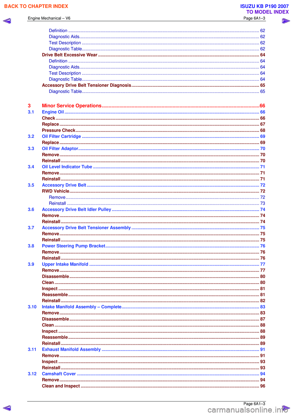
Definition ..................................................................................................................... .....................................62
Diagnostic Aids................................................................................................................................................. 62
Test Description ............................................................................................................... ................................62
Diagnostic Table............................................................................................................... ................................62
Drive Belt Excessive Wear ...................................................................................................... ............................64
Definition ..................................................................................................................... .....................................64
Diagnostic Aids................................................................................................................................................. 64
Test Description ............................................................................................................... ................................64
Diagnostic Table............................................................................................................... ................................64
Accessory Drive Belt Tensioner Diagnosis ....................................................................................... ................65
Diagnostic Table............................................................................................................... ................................65
3 Minor Service Operations ....................................................................................................... .............66
3.1 Engine Oil ..................................................................................................................... ........................................66
Check.................................................................................................................................................................... 66
Replace ........................................................................................................................ .........................................67
Pressure Check ................................................................................................................. ...................................68
3.2 Oil Filter Cartridge ........................................................................................................... ....................................69
Replace ........................................................................................................................ .........................................69
3.3 Oil Filter Adaptor............................................................................................................. .....................................70
Remove ................................................................................................................................................................. 70
Reinstall ................................................................................................................................................................ 70
3.4 Oil Level Indicator Tube ...................................................................................................................................... 71
Remove ................................................................................................................................................................. 71
Reinstall ................................................................................................................................................................ 71
3.5 Accessory Drive Belt ........................................................................................................................................... 72
RWD Vehicle ......................................................................................................................................................... 72
Remove ............................................................................................................................................................72
Reinstall ...................................................................................................................... .....................................73
3.6 Accessory Drive Belt Idler Pulley .............................................................................................. .........................74
Remove ................................................................................................................................................................. 74
Reinstall ................................................................................................................................................................ 74
3.7 Accessory Drive Belt Tensioner Assembly ........................................................................................ ...............75
Remove ................................................................................................................................................................. 75
Reinstall ................................................................................................................................................................ 75
3.8 Power Steering Pump Bracket .................................................................................................... ........................76
Remove ................................................................................................................................................................. 76
Reinstall ................................................................................................................................................................ 76
3.9 Upper Intake Manifold .......................................................................................................... ...............................77
Remove ................................................................................................................................................................. 77
Disassemble ......................................................................................................................................................... 80
Clean..................................................................................................................................................................... 80
Inspect ........................................................................................................................ ..........................................81
Reassemble .......................................................................................................................................................... 81
Reinstall ................................................................................................................................................................ 82
3.10 Intake Manifold Assembly – Complete............................................................................................ ...................83
Remove ................................................................................................................................................................. 83
Disassemble ......................................................................................................................................................... 87
Clean..................................................................................................................................................................... 88
Inspect ........................................................................................................................ ..........................................88
Reassemble .......................................................................................................................................................... 89
Reinstall ................................................................................................................................................................ 89
3.11 Exhaust Manifold Assembly ...................................................................................................... .........................91
Remove ................................................................................................................................................................. 91
Inspect ........................................................................................................................ ..........................................93
Reinstall ................................................................................................................................................................ 93
3.12 Camshaft Cover ................................................................................................................. ..................................94
Remove ................................................................................................................................................................. 94
Clean and Inspect .............................................................................................................. ..................................96
BACK TO CHAPTER INDEX
TO MODEL INDEX
ISUZU KB P190 2007
Page 2782 of 6020
Engine Mechanical – V6 Page 6A1–5
Page 6A1–5
Reinstall .............................................................................................................................................................. 192
3.19 Camshaft Sprocket – MY06 Update ................................................................................................ ..................193
Remove ............................................................................................................................................................... 193
Right-hand Side................................................................................................................ ..............................193
Left-hand Side ................................................................................................................................................ 196
Clean................................................................................................................................................................... 199
Inspect ........................................................................................................................ ........................................199
Reinstall .............................................................................................................................................................. 200
3.20 Camshaft ............................................................................................................................................................ 201
Remove ............................................................................................................................................................... 201
Right-hand Side................................................................................................................ ..............................201
Left-hand Side ................................................................................................................................................ 203
Clean................................................................................................................................................................... 204
Inspect ........................................................................................................................ ........................................205
Camshaft Visual Inspection ..................................................................................................... .......................205
Camshaft Meas urement ................................................................................................................................. 205
Reinstall .............................................................................................................................................................. 207
Right-hand Side................................................................................................................ ..............................207
Left-hand Side ................................................................................................................................................ 210
3.21 Rocker Arm......................................................................................................................................................... 213
Remove ............................................................................................................................................................... 213
Clean and Inspect .............................................................................................................. ................................213
Reinstall .............................................................................................................................................................. 214
3.22 Stationary Hydraulic Lash Adjuster ............................................................................................. ....................215
Remove ............................................................................................................................................................... 215
Clean and Inspect .............................................................................................................. ................................215
Reinstall .............................................................................................................................................................. 216
3.23 Cylinder Head Assembly ......................................................................................................... ..........................217
Remove ............................................................................................................................................................... 217
Right-hand Side (Bank 1) Cylinder Head ......................................................................................... ..............217
Left-hand Side (Bank 2) Cylinder Head .......................................................................................... ................218
Disassemble ....................................................................................................................................................... 219
Clean................................................................................................................................................................... 222
Inspect ........................................................................................................................ ........................................222
Visual Inspection .............................................................................................................. ..............................222
Cylinder Head Measurement.......................................................................................................................... 223
Valve Spring Inspection and Measurement ........................................................................................ ............225
Valve and Seat Grinding ........................................................................................................ ........................225
Assemble ....................................................................................................................... .....................................230
Reinstall .............................................................................................................................................................. 233
Right-hand Side (Bank 1) Cylinder Head ......................................................................................... ..............233
Left-hand Side (Bank 2) Cylinder Head .......................................................................................... ................234
3.24 Engine Mounts and Brackets ..................................................................................................... .......................236
Remove ............................................................................................................................................................... 236
Engine Mount Location ..................................................................................................................................... 237
Inspect ........................................................................................................................ ........................................237
Reinstall .............................................................................................................................................................. 238
4 Major Service Operations ....................................................................................................... ...........239
4.1 Engine Re moval ................................................................................................................. ................................239
Remove ............................................................................................................................................................... 240
Disassemble ....................................................................................................................................................... 252
Reassemble ........................................................................................................................................................ 253
Reinstall .............................................................................................................................................................. 253
4.2 Oil Pan and Oil Pump Suction Pipe Assembly ..................................................................................... ...........254
Remove ............................................................................................................................................................... 254
Disassemble ....................................................................................................................................................... 255
Clean................................................................................................................................................................... 255
Inspect ........................................................................................................................ ........................................256
BACK TO CHAPTER INDEX
TO MODEL INDEX
ISUZU KB P190 2007
Page 2785 of 6020
Engine Mechanical – V6 Page 6A1–8
Page 6A1–8
1 General Information
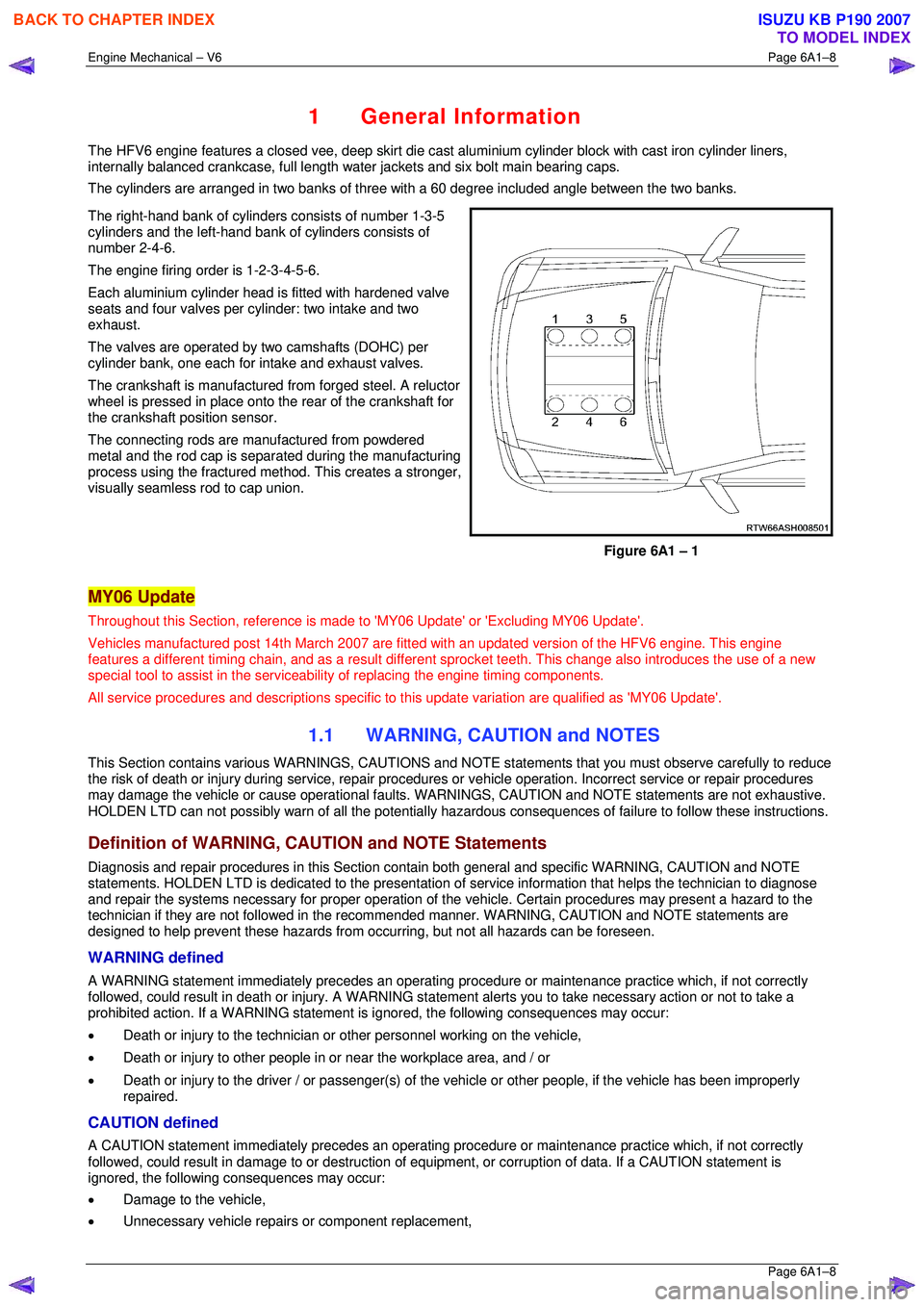
The HFV6 engine features a closed vee, deep skirt die cast aluminium cylinder block with cast iron cylinder liners,
internally balanced crankcase, full length wa ter jackets and six bolt main bearing caps.
The cylinders are arranged in two banks of three with a 60 degree included angle between the two banks.
The right-hand bank of cylinders consists of number 1-3-5
cylinders and the left-hand bank of cylinders consists of
number 2-4-6.
The engine firing order is 1-2-3-4-5-6.
Each aluminium cylinder head is fitted with hardened valve
seats and four valves per cylinder: two intake and two
exhaust.
The valves are operated by two camshafts (DOHC) per
cylinder bank, one each for intake and exhaust valves.
The crankshaft is manufactured from forged steel. A reluctor
wheel is pressed in place onto the rear of the crankshaft for
the crankshaft position sensor.
The connecting rods are m anufactured from powdered
metal and the rod cap is separ ated during the manufacturing
process using the fractured me thod. This creates a stronger,
visually seamless rod to cap union.
Figure 6A1 – 1
MY06 Update
Throughout this Section, reference is made to 'MY06 Update' or 'Excluding MY06 Update'.
Vehicles manufactured post 14th Marc h 2007 are fitted with an updated version of the HFV6 engine. This engine
features a different timing chain, and as a result different sprocket teeth. This change also introduces the use of a new
special tool to assist in the serviceab ility of replacing the engine timing components.
All service procedures and descriptions specific to this update variation are qualified as 'MY06 Update'.
1.1 WARNING, CAUTION and NOTES
This Section contains various WARNING S, CAUTIONS and NOTE statements that y ou must observe carefully to reduce
the risk of death or injury during servic e, repair procedures or vehicle operation. Incorrect service or repair procedures
may damage the vehicle or cause operat ional faults. WARNINGS, CAUTION and NOTE statements are not exhaustive.
HOLDEN LTD can not possibly warn of a ll the potentially hazardous consequences of failure to follow these instructions.
Definition of WARNING, CAUTION and NOTE Statements
Diagnosis and repair procedures in this Section contain both general and specific WARNING, CAUTION and NOTE
statements. HOLDEN LTD is dedicated to the presentation of service information that helps the technician to diagnose
and repair the systems necessary for proper operation of the vehicle. Certain procedures may present a hazard to the
technician if they are not followed in the reco mmended manner. WARNING, CAUTION and NOTE statements are
designed to help prevent these hazards from o ccurring, but not all hazards can be foreseen.
WARNING defined
A WARNING statement immediately precedes an operating procedure or maint enance practice which, if not correctly
followed, could result in death or injury . A WARNING statement alerts you to ta ke necessary action or not to take a
prohibited action. If a WARNING statement is ignored, the following consequences may occur:
• Death or injury to the technician or other personnel working on the vehicle,
• Death or injury to other people in or near the workplace area, and / or
• Death or injury to the driver / or passenger(s) of the vehicle or other people, if the vehicle has been improperly
repaired.
CAUTION defined
A CAUTION statement immediately prec edes an operating procedure or maintenance practice which, if not correctly
followed, could result in damage to or destruction of equi pment, or corruption of data. If a CAUTION statement is
ignored, the following consequences may occur:
• Damage to the vehicle,
• Unnecessary vehicle repairs or component replacement,
BACK TO CHAPTER INDEX
TO MODEL INDEX
ISUZU KB P190 2007
Page 2788 of 6020
Engine Mechanical – V6 Page 6A1–11
Page 6A1–11
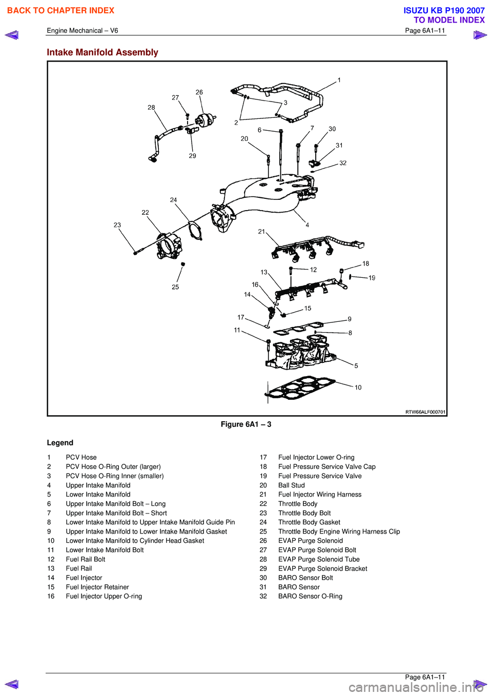
Intake Manifold Assembly
Figure 6A1 – 3
Legend
1 PCV Hose
2 PCV Hose O-Ring Outer (larger)
3 PCV Hose O-Ring Inner (smaller)
4 Upper Intake Manifold
5 Lower Intake Manifold
6 Upper Intake Manifold Bolt – Long
7 Upper Intake Manifold Bolt – Short
8 Lower Intake Manifold to Upper Intake Manifold Guide Pin
9 Upper Intake Manifold to Lower Intake Manifold Gasket
10 Lower Intake Manifold to Cylinder Head Gasket
11 Lower Intake Manifold Bolt
12 Fuel Rail Bolt
13 Fuel Rail
14 Fuel Injector
15 Fuel Injector Retainer
16 Fuel Injector Upper O-ring 17 Fuel Injector Lower O-ring
18 Fuel Pressure Service Valve Cap
19 Fuel Pressure Service Valve
20 Ball Stud
21 Fuel Injector Wiring Harness
22 Throttle Body
23 Throttle Body Bolt
24 Throttle Body Gasket
25 Throttle Body Engine Wiring Harness Clip
26 EVAP Purge Solenoid
27 EVAP Purge Solenoid Bolt
28 EVAP Purge Solenoid Tube
29 EVAP Purge Solenoid Bracket
30 BARO Sensor Bolt
31 BARO Sensor
32 BARO Sensor O-Ring
BACK TO CHAPTER INDEX
TO MODEL INDEX
ISUZU KB P190 2007
Page 2793 of 6020

Engine Mechanical – V6 Page 6A1–16
Page 6A1–16
Oil Pump
Figure 6A1 – 8
Legend
1 Lower Primary Timing Chain Guide
2 Lower Primary Timing Chain Guide Bolt
3 Oil Pump Housing
4 Oil Pump Cover
5 Oil Pump Gerotor Outer Ring
6 Oil Pump Gerotor Inner Ring 7 Oil Pump Cover Bolt
8 Oil Pressure Relief Valve Bore Plug
9 Oil Pressure Relief Valve Spring
10 Oil Pressure Relief Valve
11 Oil Pressure Relief Valve Bore Plug Retainer Clip
12 Oil Pump Bolt
NOTE
Oil pump components are not serviced
individually.
BACK TO CHAPTER INDEX
TO MODEL INDEX
ISUZU KB P190 2007