Page 2566 of 6020

Engine Mechanical – V6 Page 6A1–87
3.14 Crankshaft Front Seal
Replace
1 Remove the crankshaft balancer assembly, refer to 3.13 Crankshaft Balancer Assembly.
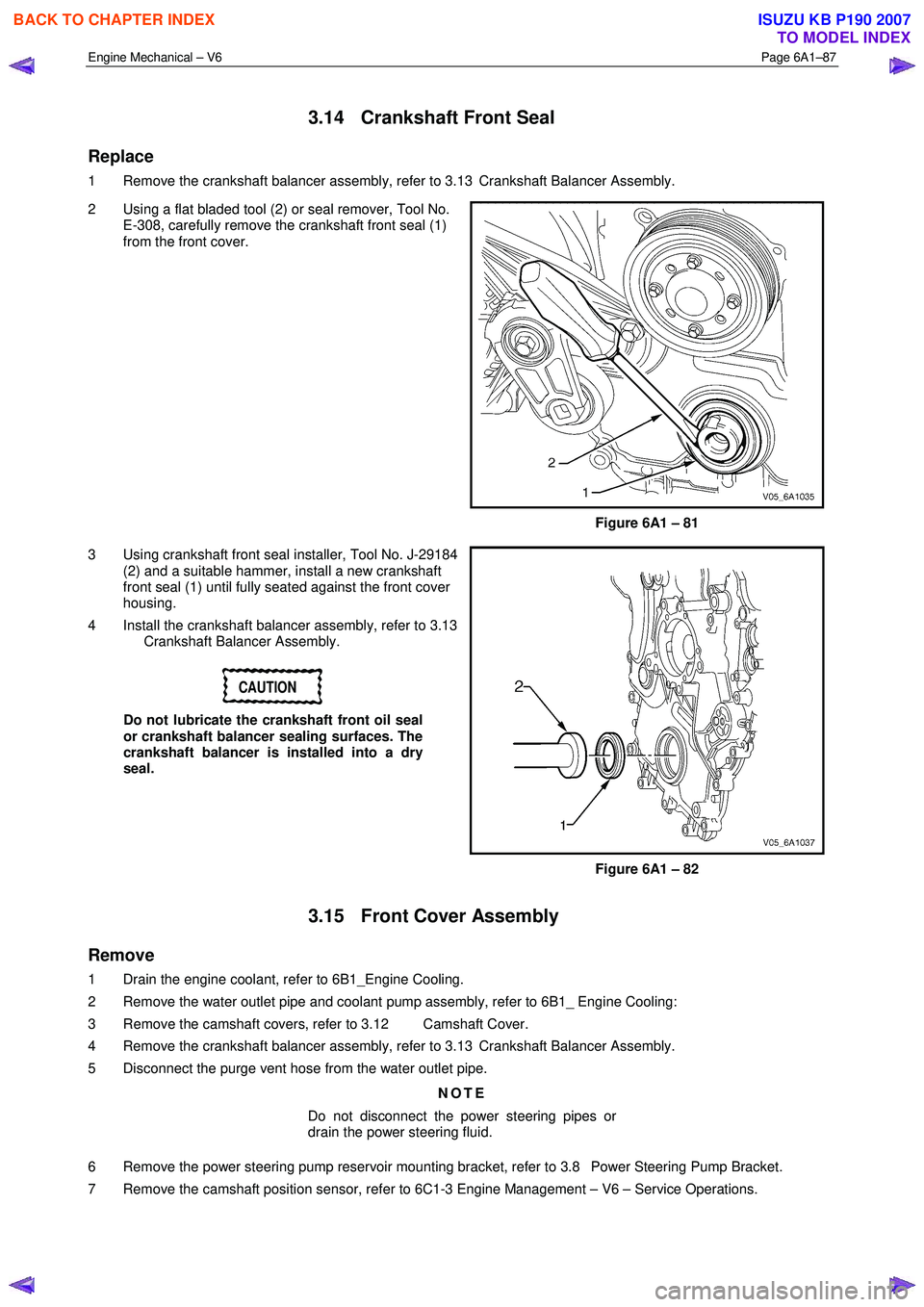
2 Using a flat bladed tool (2) or seal remover, Tool No. E-308, carefully remove the crankshaft front seal (1)
from the front cover.
Figure 6A1 – 81
3 Using crankshaft front seal installer, Tool No. J-29184 (2) and a suitable hammer, install a new crankshaft
front seal (1) until fully seated against the front cover
housing.
4 Install the crankshaft balancer assembly, refer to 3.13 Crankshaft Balancer Assembly.
CAUTION
Do not lubricate the crankshaft front oil seal
or crankshaft balancer sealing surfaces. The
crankshaft balancer is installed into a dry
seal.
Figure 6A1 – 82
3.15 Front Cover Assembly
Remove
1 Drain the engine coolant, refer to 6B1_Engine Cooling.
2 Remove the water outlet pipe and coolant pump assembly, refer to 6B1_ Engine Cooling:
3 Remove the camshaft covers, refer to 3.12 Camshaft Cover.
4 Remove the crankshaft balancer assembly, refer to 3.13 Crankshaft Balancer Assembly.
5 Disconnect the purge vent hose from the water outlet pipe.
NOTE
Do not disconnect the power steering pipes or
drain the power steering fluid.
6 Remove the power steering pump reservoir mounting bracket, refer to 3.8 Power Steering Pump Bracket.
7 Remove the camshaft position sensor, refer to 6C1-3 Engine Management – V6 – Service Operations.
BACK TO CHAPTER INDEX
TO MODEL INDEX
ISUZU KB P190 2007
Page 2575 of 6020
Engine Mechanical – V6 Page 6A1–96
Remove
Right-hand Secondary Timing Chain
CAUTION
After removing the upper intake manifold, and
spark plugs, plug any openings to prevent dirt
and other contaminants from entering.
1 Remove the engine front cover assembly, refer to 3.15 Front Cover Assembly.
2 Remove the spark plugs to aid crankshaft/engine rotation, refer to 6C1-3 Engine Management – V6 – Service Operations.
3 Install Tool No. EN46111 (1) onto the crankshaft (2).
Figure 6A1 – 101
4 Using Tool No. EN46111 (1), rotate the crankshaft in a clockwise direction until the crankshaft sprocket
timing mark (2) is aligned with the indexing mark (3)
on the oil pump housing.
Figure 6A1 – 102
BACK TO CHAPTER INDEX
TO MODEL INDEX
ISUZU KB P190 2007
Page 2580 of 6020
Engine Mechanical – V6 Page 6A1–101
NOTE
Do not remove the primary timing chain lower
guide (1). The primary timing chain lower guide
is not serviced separately. If the primary timing
chain lower guide requires replacement, the oil
pump assembly (2) must be replaced.
Figure 6A1 – 115
6 Remove the primary timing chain (1). NOTE
For ease of removal, remove the chain from the
crankshaft sprocket, before attempting to
remove from the camshaft intermediate
driveshaft sprockets.
Figure 6A1 – 116
7 If required, remove the right-hand camshaft intermediate driveshaft sprocket bolt (1) and remove
the sprocket (2).
Figure 6A1 – 117
BACK TO CHAPTER INDEX
TO MODEL INDEX
ISUZU KB P190 2007
Page 2586 of 6020

Engine Mechanical – V6 Page 6A1–107
Crankshaft Sprocket
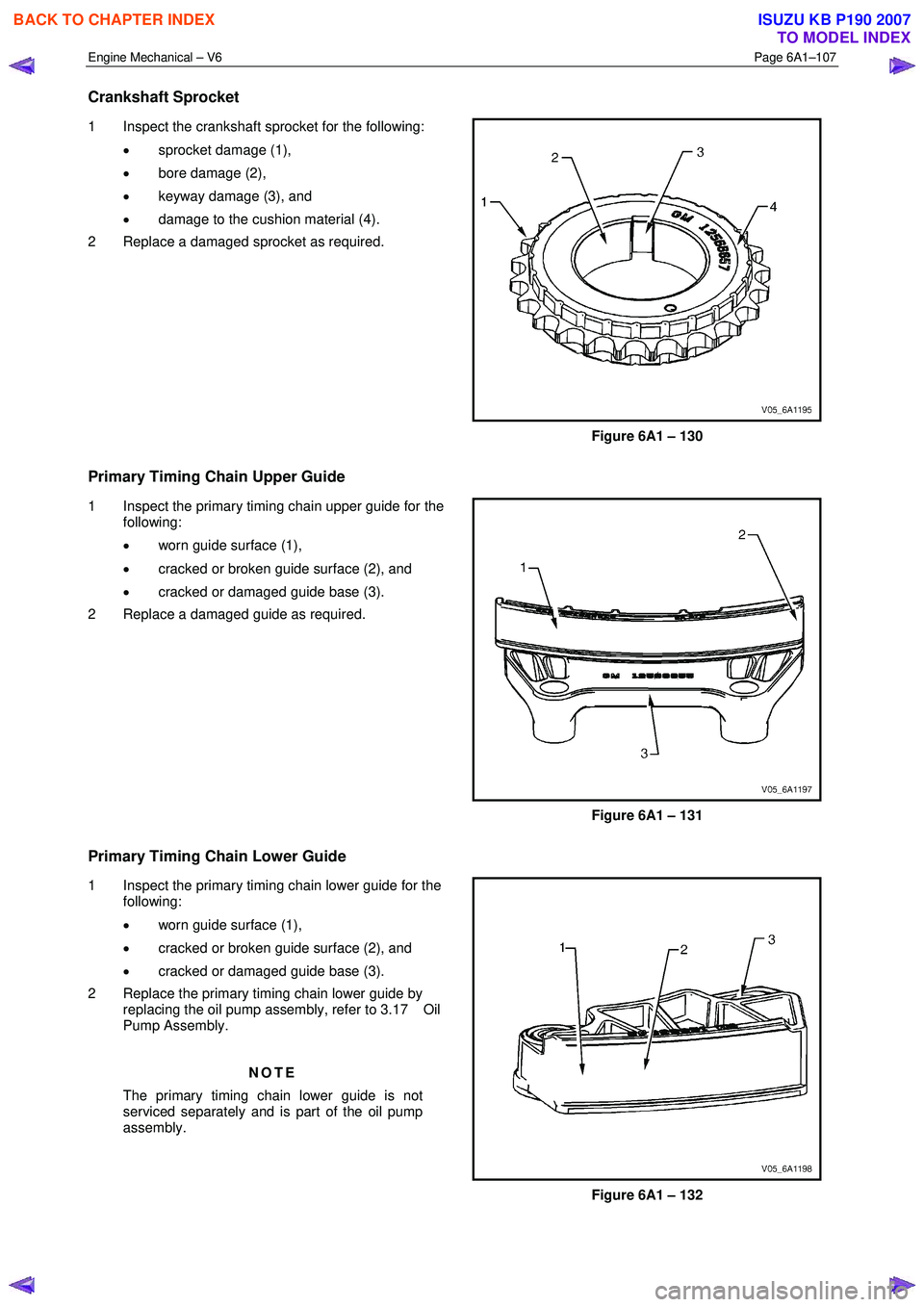
1 Inspect the crankshaft sprocket for the following:
• sprocket damage (1),
• bore damage (2),
• keyway damage (3), and
• damage to the cushion material (4).
2 Replace a damaged sprocket as required.
Figure 6A1 – 130
Primary Timing Chain Upper Guide
1 Inspect the primary timing chain upper guide for the following:
• worn guide surface (1),
• cracked or broken guide surface (2), and
• cracked or damaged guide base (3).
2 Replace a damaged guide as required.
Figure 6A1 – 131
Primary Timing Chain Lower Guide
1 Inspect the primary timing chain lower guide for the following:
• worn guide surface (1),
• cracked or broken guide surface (2), and
• cracked or damaged guide base (3).
2 Replace the primary timing chain lower guide by replacing the oil pump assembly, refer to 3.17 Oil
Pump Assembly.
NOTE
The primary timing chain lower guide is not
serviced separately and is part of the oil pump
assembly.
Figure 6A1 – 132
BACK TO CHAPTER INDEX
TO MODEL INDEX
ISUZU KB P190 2007
Page 2603 of 6020
Engine Mechanical – V6 Page 6A1–124
11 Ensure all the timing marks (1, 2 and 3) are properly
aligned with the bright plated timing chain links (4, 5
and 6).
Figure 6A1 – 176
NOTE
Do not remove the primary timing chain lower
guide (1). The primary timing chain lower guide
is not serviced separately. If the primary timing
chain lower guide must be replaced, the oil
pump assembly (2) must be replaced.
Figure 6A1 – 177
12 Ensure the primary timing chain upper guide is selected and orientated correctly.
Figure 6A1 – 178
BACK TO CHAPTER INDEX
TO MODEL INDEX
ISUZU KB P190 2007
Page 2615 of 6020
Engine Mechanical – V6 Page 6A1–136
28 Verify all primary and secondary timing chain timing
mark alignments (1 to 18).
29 Remove Tool No. EN 46105 and EN 46105-2 from the left and right-hand cylinder head camshafts.
30 Reinstall the spark plugs. Refer to 6C1-3 Engine Management – V6 – Service Operations.
31 Reinstall the engine front cover assembly, refer to 3.15 Front Cover Assembly.
Figure 6A1 – 211
3.17 Oil Pump Assembly
Remove
NOTE
Do not remove the left-hand bank idler sprocket.
1 Remove the primary timing chain and crankshaft sprocket, refer to 3.16 Timing Chains, Tensioners, Shoes and Guides.
2 Remove the three bolts (1) attaching the oil pump (2).
3 Remove the oil pump assembly.
Figure 6A1 – 212
BACK TO CHAPTER INDEX
TO MODEL INDEX
ISUZU KB P190 2007
Page 2616 of 6020
Engine Mechanical – V6 Page 6A1–137
Disassemble
CAUTION
There are no serviceable components within
the oil pump. Disassemble the pump only to
diagnose an oil related concern. A
disassembled oil pump must not be reused: it
must be replaced.
1 Remove the two bolts (1) attaching the primary timing chain lower guide (2) and remove the guide.
CAUTION
The primary timing chain lower guide is not
serviced separately and is part of the oil
pump assembly. If it is removed from the
pump assembly, the guide and the pump
must be replaced.
Figure 6A1 – 213
2 Remove the seven bolts (2) attaching the oil pump cover to the oil pump housing (1) and remove the
cover from the housing.
Figure 6A1 – 214
BACK TO CHAPTER INDEX
TO MODEL INDEX
ISUZU KB P190 2007
Page 2619 of 6020
Engine Mechanical – V6 Page 6A1–140
4 Inspect the outer driven gear for damage.
Figure 6A1 – 220
5 Inspect the oil pump relief valve components for debris or damage.
Figure 6A1 – 221
6 Inspect the primary camshaft chain lower guide for damage. If replacement of the primary camshaft chain
lower guide is required, replace the entire oil pump
assembly as the primary camshaft chain lower guide
is not serviceable separately.
7 If debris or damage is present within the oil pump, further inspection of all of the engine components is
required.
Figure 6A1 – 222
BACK TO CHAPTER INDEX
TO MODEL INDEX
ISUZU KB P190 2007