2007 ISUZU KB P190 service
[x] Cancel search: servicePage 2530 of 6020
Engine Mechanical – V6 Page 6A1–51
• the incorrect installation or mounting of an accessory drive component,
• the incorrect installation of an accessory drive component pulley, or
• a damaged or bent accessory drive pulley.
Test for a misaligned pulley using a suitable straight edge in the pulley grooves across two or more pulleys. If a misaligned pulley is found, refer to the service information for the particular component, for the correct pulley
replacement procedures.
5 Inspecting the pulleys should include an inspection for dents or other damage that would prevent the drive belt from seating correctly in all of the pulley grooves or on the smooth surface of a pulley when the back side of the belt is
used.
6 Accessory drive component mounting brackets that are bent will cause the drive belt to fall off.
7 Inspection of the fasteners can eliminate the possibility that an incorrect fastener was installed. Missing, loose or incorrect fasteners may cause pulley misalignment from the fasteners moving under load. Over-tightening of the
fasteners may cause deflection of mounting brackets and result in misaligned accessory drive pulleys.
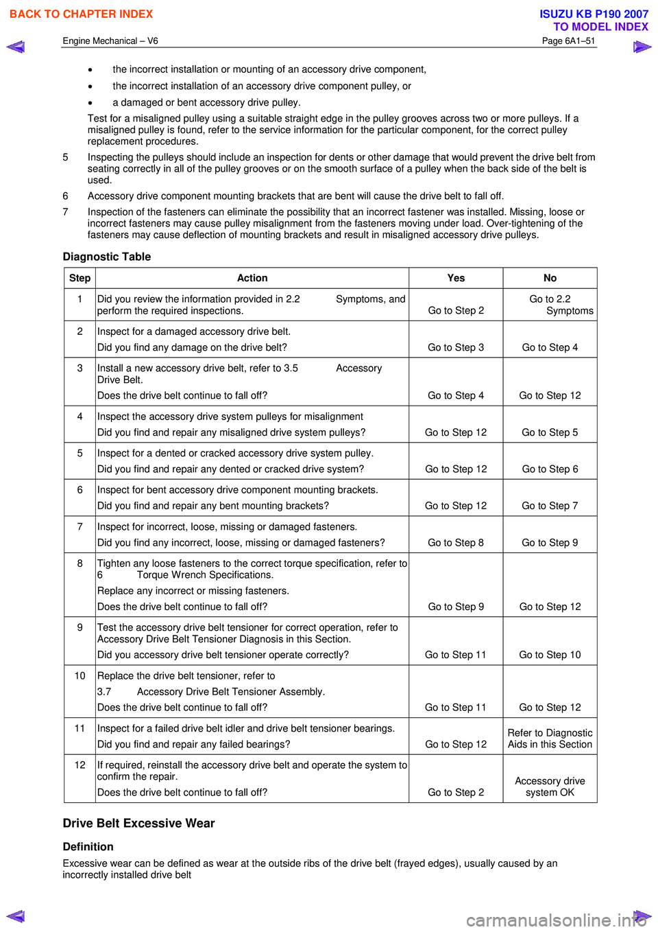
Diagnostic Table
Step Action Yes No
1 Did you review the information provided in 2.2 Symptoms, and
perform the required inspections. Go to Step 2 Go to 2.2
Symptoms
2 Inspect for a damaged accessory drive belt.
Did you find any damage on the drive belt? Go to Step 3 Go to Step 4
3 Install a new accessory drive belt, refer to 3.5 Accessory Drive Belt.
Does the drive belt continue to fall off? Go to Step 4 Go to Step 12
4 Inspect the accessory drive system pulleys for misalignment
Did you find and repair any misaligned drive system pulleys? Go to Step 12 Go to Step 5
5 Inspect for a dented or cracked accessory drive system pulley. Did you find and repair any dented or cracked drive system? Go to Step 12 Go to Step 6
6 Inspect for bent accessory drive component mounting brackets.
Did you find and repair any bent mounting brackets? Go to Step 12 Go to Step 7
7 Inspect for incorrect, loose, missing or damaged fasteners. Did you find any incorrect, loose, missing or damaged fasteners? Go to Step 8 Go to Step 9
8 Tighten any loose fasteners to the correct torque specification, refer to 6 Torque W rench Specifications.
Replace any incorrect or missing fasteners.
Does the drive belt continue to fall off? Go to Step 9 Go to Step 12
9 Test the accessory drive belt tensioner for correct operation, refer to
Accessory Drive Belt Tensioner Diagnosis in this Section.
Did you accessory drive belt tensioner operate correctly? Go to Step 11 Go to Step 10
10 Replace the drive belt tensioner, refer to
3.7 Accessory Drive Belt Tensioner Assembly.
Does the drive belt continue to fall off? Go to Step 11 Go to Step 12
11 Inspect for a failed drive belt idler and drive belt tensioner bearings.
Did you find and repair any failed bearings? Go to Step 12 Refer to Diagnostic
Aids in this Section
12 If required, reinstall the accessory drive belt and operate the system to confirm the repair.
Does the drive belt continue to fall off? Go to Step 2 Accessory drive
system OK
Drive Belt Excessive Wear
Definition
Excessive wear can be defined as wear at the outside ribs of the drive belt (frayed edges), usually caused by an
incorrectly installed drive belt
BACK TO CHAPTER INDEX
TO MODEL INDEX
ISUZU KB P190 2007
Page 2532 of 6020
Engine Mechanical – V6 Page 6A1–53
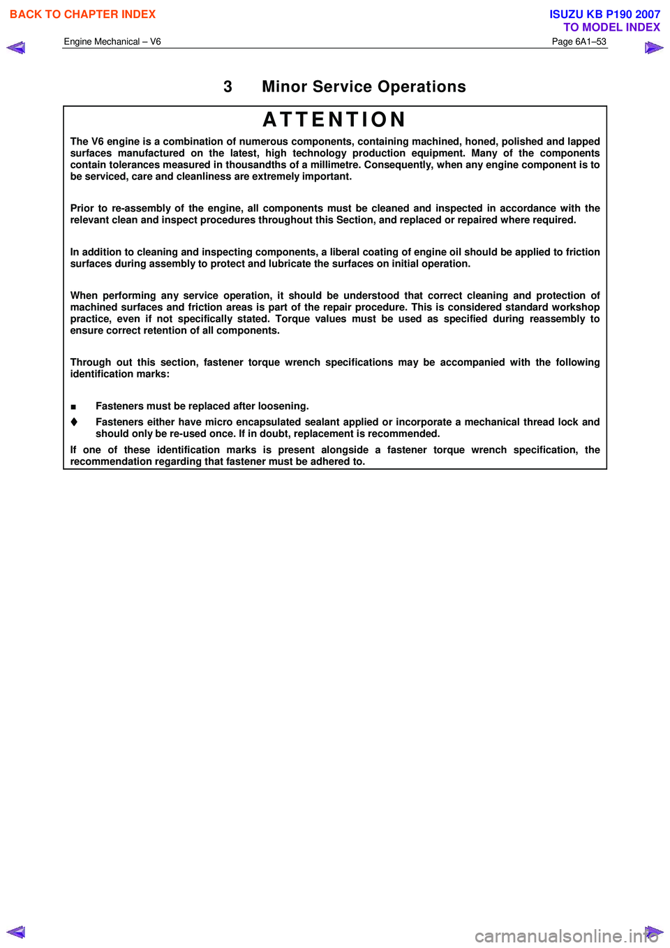
3 Minor Service Operations
ATTENTION
The V6 engine is a combination of numerous components, containing machined, honed, polished and lapped
surfaces manufactured on the latest, high technology production equipment. Many of the components
contain tolerances measured in thousandths of a millimetre. Consequently, when any engine component is to
be serviced, care and cleanliness are extremely important.
Prior to re-assembly of the engine, all components must be cleaned and inspected in accordance with the
relevant clean and inspect procedures throughout this Section, and replaced or repaired where required.
In addition to cleaning and inspecting components, a liberal coating of engine oil should be applied to friction
surfaces during assembly to protect and lubricate the surfaces on initial operation.
When performing any service operation, it should be understood that correct cleaning and protection of
machined surfaces and friction areas is part of the repair procedure. This is considered standard workshop
practice, even if not specifically stated. Torque values must be used as specified during reassembly to
ensure correct retention of all components.
Through out this section, fastener torque wrench specifications may be accompanied with the following
identification marks:
■ Fasteners must be replaced after loosening.
Fasteners either have micro encapsulated sealant applied or incorporate a mechanical thread lock and
should only be re-used once. If in doubt, replacement is recommended.
If one of these identification marks is present alongside a fastener torque wrench specification, the
recommendation regarding that fastener must be adhered to.
BACK TO CHAPTER INDEX
TO MODEL INDEX
ISUZU KB P190 2007
Page 2534 of 6020
Engine Mechanical – V6 Page 6A1–55
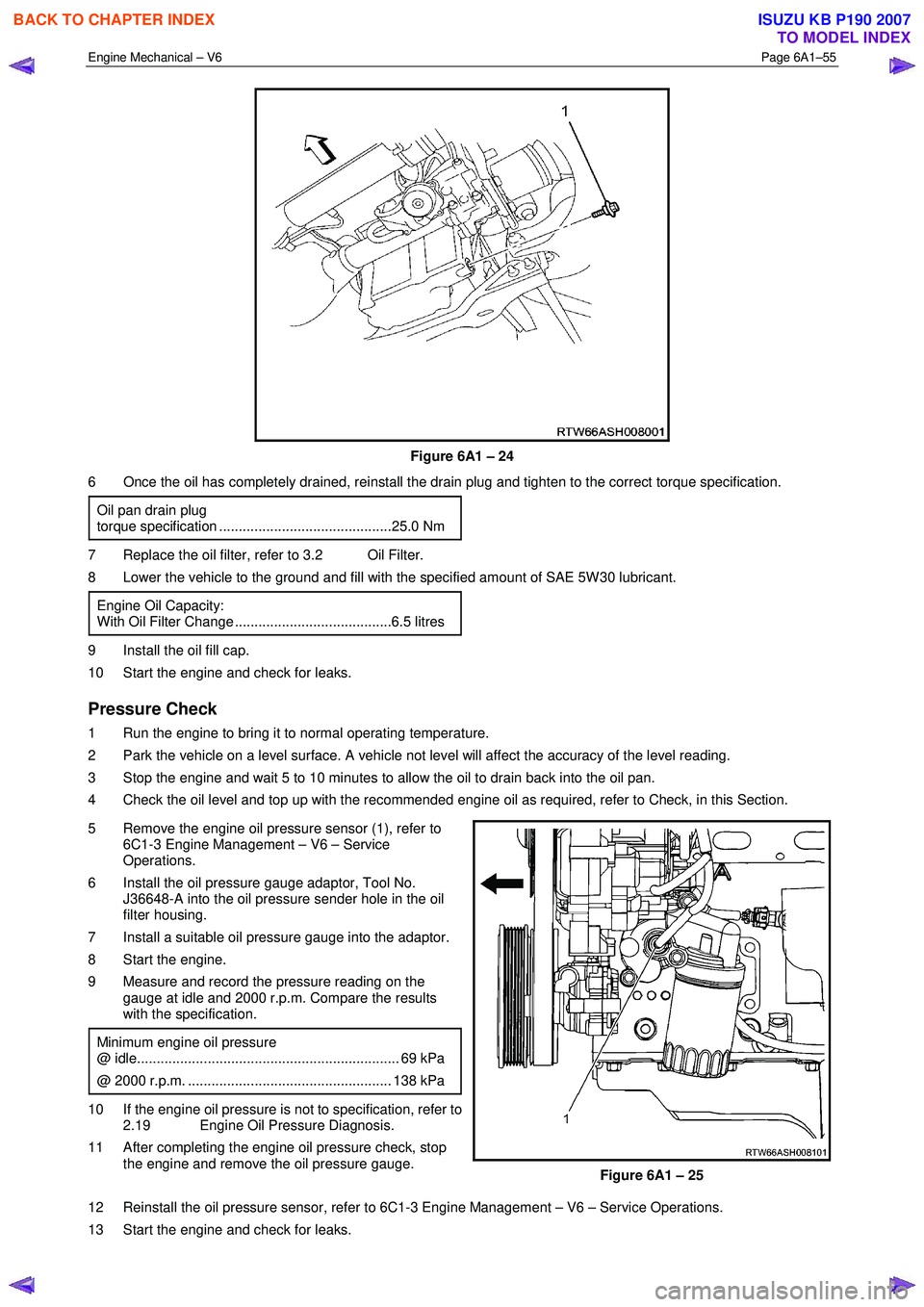
Figure 6A1 – 24
6 Once the oil has completely drained, reinstall the drain plug and tighten to the correct torque specification.
Oil pan drain plug
torque specification ............................................25.0 Nm
7 Replace the oil filter, refer to 3.2 Oil Filter.
8 Lower the vehicle to the ground and fill with the specified amount of SAE 5W 30 lubricant.
Engine Oil Capacity:
With Oil Filter Change ........................................6.5 litres
9 Install the oil fill cap.
10 Start the engine and check for leaks.
Pressure Check
1 Run the engine to bring it to normal operating temperature.
2 Park the vehicle on a level surface. A vehicle not level will affect the accuracy of the level reading.
3 Stop the engine and wait 5 to 10 minutes to allow the oil to drain back into the oil pan.
4 Check the oil level and top up with the recommended engine oil as required, refer to Check, in this Section.
5 Remove the engine oil pressure sensor (1), refer to 6C1-3 Engine Management – V6 – Service
Operations.
6 Install the oil pressure gauge adaptor, Tool No. J36648-A into the oil pressure sender hole in the oil
filter housing.
7 Install a suitable oil pressure gauge into the adaptor.
8 Start the engine.
9 Measure and record the pressure reading on the gauge at idle and 2000 r.p.m. Compare the results
with the specification.
Minimum engine oil pressure
@ idle................................................................... 69 kPa
@ 2000 r.p.m. .................................................... 138 kPa
10 If the engine oil pressure is not to specification, refer to 2.19 Engine Oil Pressure Diagnosis.
11 After completing the engine oil pressure check, stop the engine and remove the oil pressure gauge.
Figure 6A1 – 25
12 Reinstall the oil pressure sensor, refer to 6C1-3 Engine Management – V6 – Service Operations.
13 Start the engine and check for leaks.
BACK TO CHAPTER INDEX
TO MODEL INDEX
ISUZU KB P190 2007
Page 2535 of 6020
Engine Mechanical – V6 Page 6A1–56
3.2 Oil Filter Cartridge
Replace
NOTE
• The oil filter cartridge should be replaced at
the correct time or distance intervals, refer to
0B Lubrication and Service.
• The oil filter cartridge should also be replaced
whenever the engine oil is suspected to have
been contaminated by foreign material.
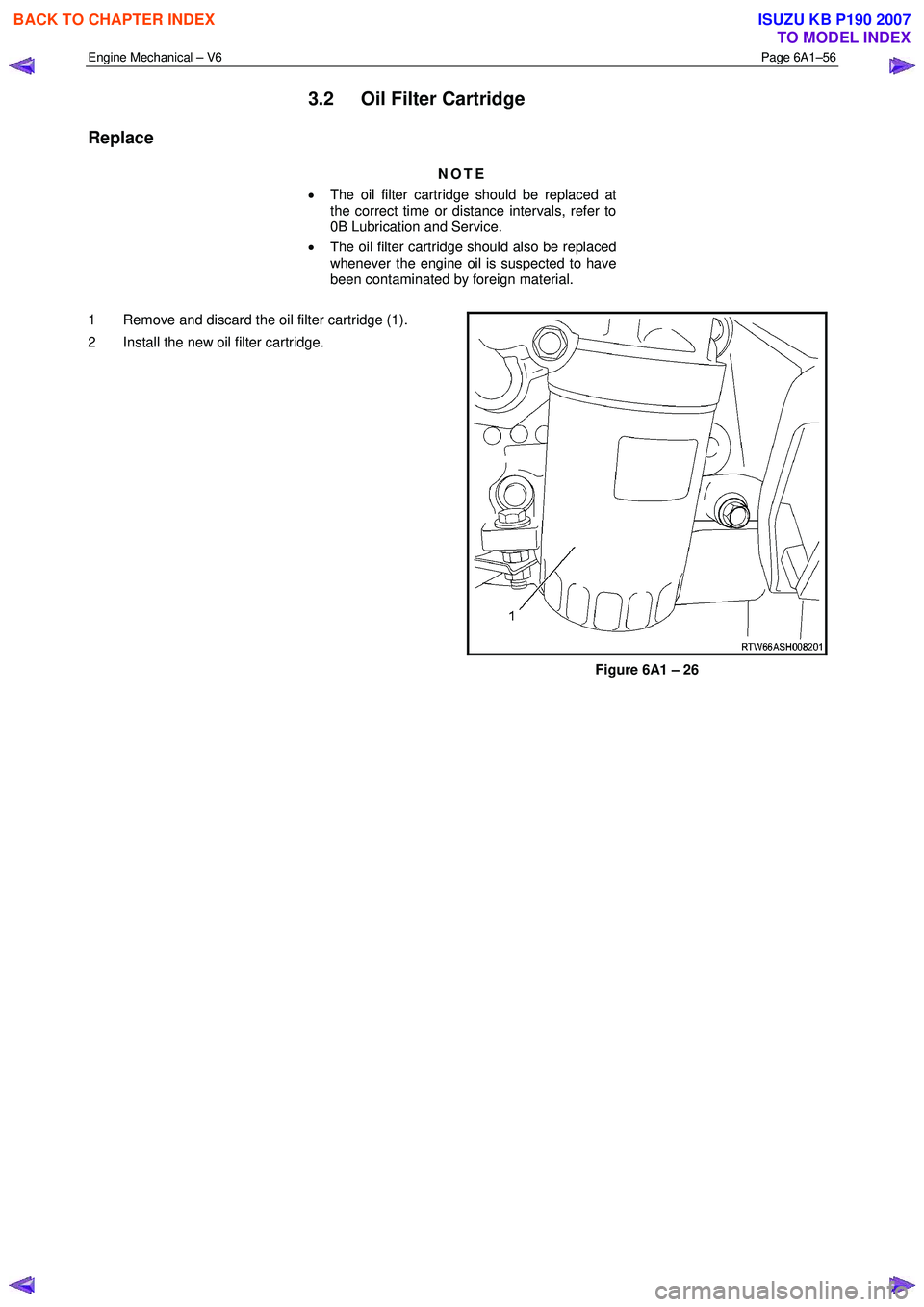
1 Remove and discard the oil filter cartridge (1).
2 Install the new oil filter cartridge.
Figure 6A1 – 26
BACK TO CHAPTER INDEX
TO MODEL INDEX
ISUZU KB P190 2007
Page 2538 of 6020
Engine Mechanical – V6 Page 6A1–59
3.5 Accessory Drive Belt
RWD Vehicle
Remove
1 Remove the air intake duct from between the air flow meter and the throttle body, refer to 6C1-3 Engine
Management – V6 – Service Operations.
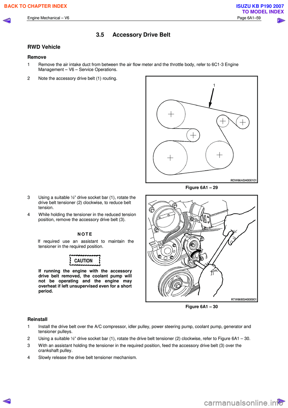
2 Note the accessory drive belt (1) routing.
Figure 6A1 – 29
3 Using a suitable ½” drive socket bar (1), rotate the drive belt tensioner (2) clockwise, to reduce belt
tension.
4 W hile holding the tensioner in the reduced tension position, remove the accessory drive belt (3).
NOTE
If required use an assistant to maintain the tensioner in the required position.
CAUTION
If running the engine with the accessory
drive belt removed, the coolant pump will
not be operating and the engine may
overheat if left unsupervised even for a short
period.
Figure 6A1 – 30
Reinstall
1 Install the drive belt over the A/C compressor, idler pulley, power steering pump, coolant pump, generator and tensioner pulleys.
2 Using a suitable ½” drive socket bar (1), rotate the drive belt tensioner (2) clockwise, refer to Figure 6A1 – 30.
3 W ith an assistant holding the tensioner in the required position, feed the accessory drive belt (3) over the crankshaft pulley.
4 Slowly release the drive belt tensioner mechanism.
BACK TO CHAPTER INDEX
TO MODEL INDEX
ISUZU KB P190 2007
Page 2539 of 6020
Engine Mechanical – V6 Page 6A1–60
NOTE
Ensure the drive belt ribs are correctly aligned
with the grooves in the accessory drive pulleys or
damage to the drive belt and accessory drive
components and pulleys may occur.
5 Reinstall the air intake duct to the air flow meter and the throttle body, refer to 6C1-3 Engine Management – V6 – Service Operations.
6 Run the engine to ensure correct operation.
3.6 Accessory Drive Belt Idler Pulley
Remove
1 Remove the accessory drive belt, refer to 3.5 Accessory Drive Belt.
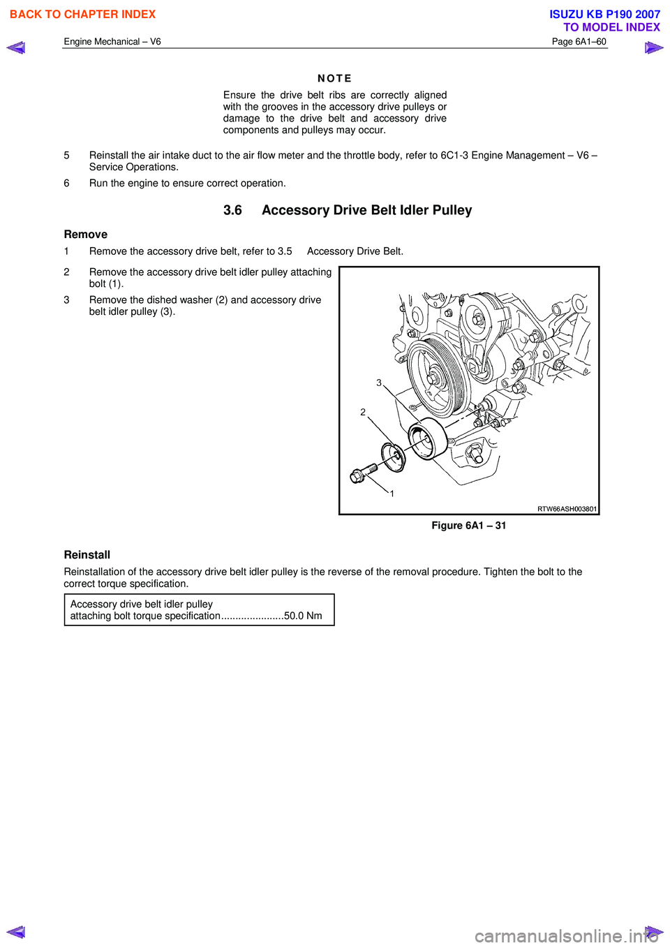
2 Remove the accessory drive belt idler pulley attaching bolt (1).
3 Remove the dished washer (2) and accessory drive belt idler pulley (3).
Figure 6A1 – 31
Reinstall
Reinstallation of the accessory drive belt idler pulley is the reverse of the removal procedure. Tighten the bolt to the
correct torque specification.
Accessory drive belt idler pulley
attaching bolt torque specification ......................50.0 Nm
BACK TO CHAPTER INDEX
TO MODEL INDEX
ISUZU KB P190 2007
Page 2540 of 6020
Engine Mechanical – V6 Page 6A1–61
3.7 Accessory Drive Belt Tensioner
Assembly
Remove
1 Remove the accessory drive belt, refer to 3.5 Accessory Drive Belt.
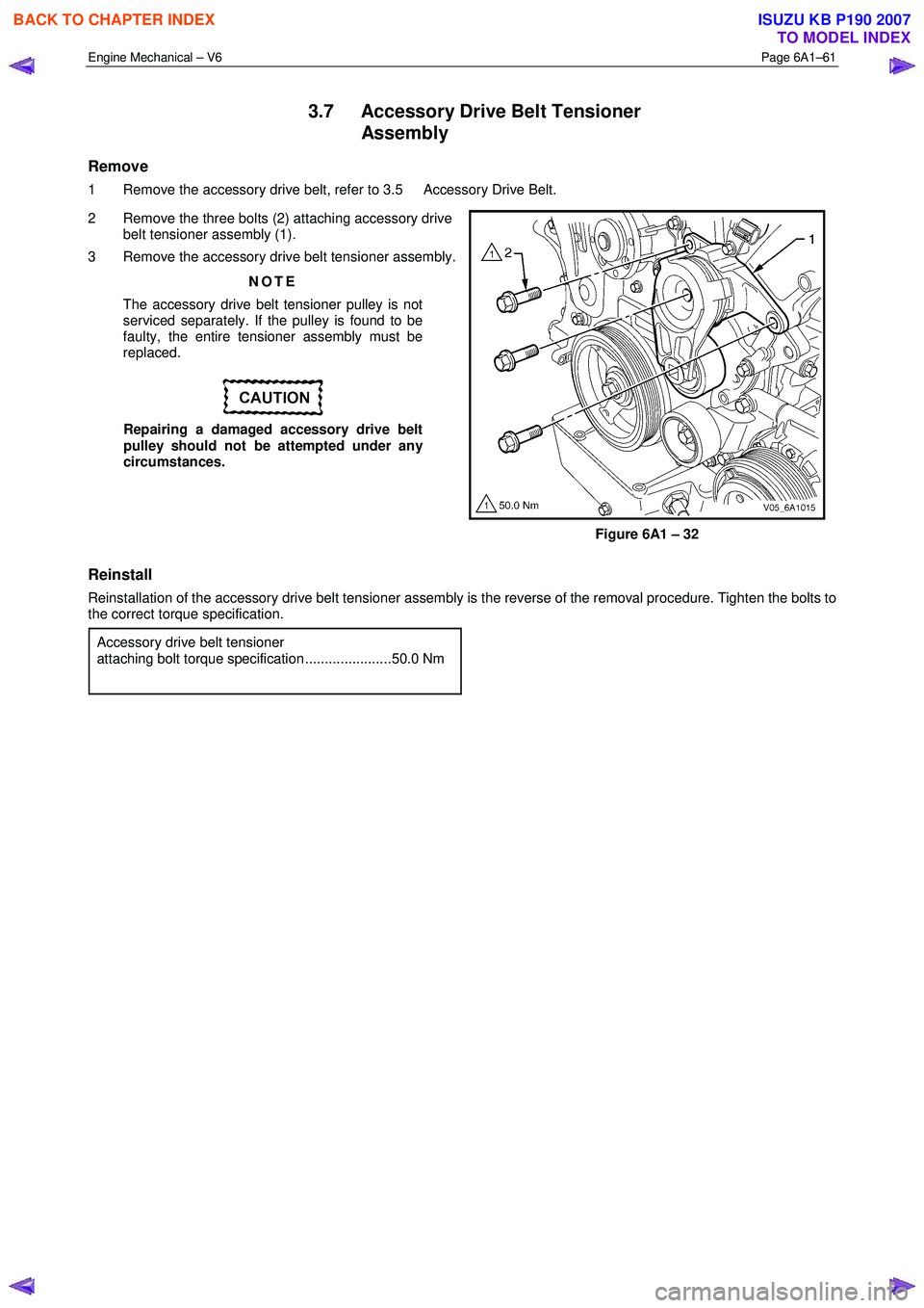
2 Remove the three bolts (2) attaching accessory drive belt tensioner assembly (1).
3 Remove the accessory drive belt tensioner assembly.
NOTE
The accessory drive belt tensioner pulley is not
serviced separately. If the pulley is found to be
faulty, the entire tensioner assembly must be
replaced.
Repairing a damaged accessory drive belt
pulley should not be attempted under any
circumstances.
Figure 6A1 – 32
Reinstall
Reinstallation of the accessory drive belt tensioner assembly is the reverse of the removal procedure. Tighten the bolts to
the correct torque specification.
Accessory drive belt tensioner
attaching bolt torque specification ......................50.0 Nm
BACK TO CHAPTER INDEX
TO MODEL INDEX
ISUZU KB P190 2007
Page 2541 of 6020
Engine Mechanical – V6 Page 6A1–62
3.8 Power Steering Pump Bracket
Remove
1 Remove the power steering pump and reservoir, refer to 3B_Steering.
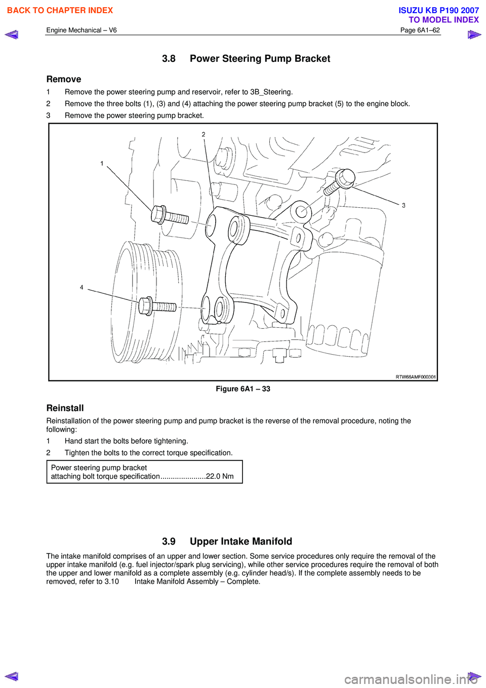
2 Remove the three bolts (1), (3) and (4) attaching the power steering pump bracket (5) to the engine block.
3 Remove the power steering pump bracket.
Figure 6A1 – 33
Reinstall
Reinstallation of the power steering pump and pump bracket is the reverse of the removal procedure, noting the
following:
1 Hand start the bolts before tightening.
2 Tighten the bolts to the correct torque specification.
Power steering pump bracket
attaching bolt torque specification ......................22.0 Nm
3.9 Upper Intake Manifold
The intake manifold comprises of an upper and lower section. Some service procedures only require the removal of the
upper intake manifold (e.g. fuel injector/spark plug servicing), while other service procedures require the removal of both
the upper and lower manifold as a complete assembly (e.g. cylinder head/s). If the complete assembly needs to be
removed, refer to 3.10 Intake Manifold Assembly – Complete.
BACK TO CHAPTER INDEX
TO MODEL INDEX
ISUZU KB P190 2007