2007 ISUZU KB P190 service
[x] Cancel search: servicePage 2677 of 6020
Engine Mechanical – V6 Page 6A1–198
k Timing chains, tensioners, shoes, guides & sprockets, refer to 3.16 Timing Chains, Tensioners, Shoes and
Guides.
l Cylinder head assemblies, refer to 3.22 Cylinder Head Assembly.
m Oil pan assembly, refer to 4.2 Oil Pan and Oil Pump Suction Pipe Assembly.
n Piston and connecting rod assemblies, refer to 4.5 Pistons, Pins, Rings, Connecting Rods and Big-end Bearings.
o Crankshaft assembly, refer to 4.6 Crankshaft and Main Bearings.
p Piston oil nozzles, refer 4.5 Pistons, Pins, Rings, Connecting Rods and Big-end Bearings.
Reassemble
Reassembly of the engine assembly is the reverse of the disassembly procedure.
Reinstall
Reinstallation of the engine assembly is the reverse to the removal procedure, noting the following:
NOTE
Refer to 6 Torque Wrench Specifications
for the correct torque specifications.
1 Tighten the fasteners to the correct torque specification.
Engine ground connector bolt
torque specification ............................................10.0 Nm
Power steering high pressure line
attaching bolt torque specification .............8.0 – 12.0 Nm
Power steering high pressure line
flare nut torque specification ...................25.0 – 35.0 Nm
Engine mount to frame attaching bolt
torque specification .................................44.0 – 60.0 Nm
Knock Sensor Attaching Nut
torque specification ............................................23.0 Nm
2 Use only the specified engine lubricant type and quantity. It is recommended that a fluorescent oil dye, such as that contained in J 28481-B, be added to assist in any future oil leak diagnosis.
3 Fill the cooling system with the correct quantity and grade of coolant, refer to 6B1 Engine Cooling – V6.
4 Check transmission fluid level, replenishing as required, using the specified lubricant for the transmission fitted, refer to 7C1 Automatic – 4L60E – General Information.
5 Disable the ignition system, refer to 6C1-3 Engine Management – V6 – Service Operations.
6 Crank the engine several times. Listen for any unusual noises or evidence that parts are binding.
7 Enable the ignition system. Start the engine and listen for any unusual noises.
8 Check the vehicle oil pressure gauge or warning indicator and confirm the engine has acceptable oil pressure. If required, install an oil pressure gauge and measure the engine oil pressure, refer to 2.19 Engine Oil Pressure
Diagnosis.
9 Run the engine at about 1,000 r.p.m. until the engine has reached normal operating temperature.
10 Listen for any unusual noises.
11 Check for oil, fuel, coolant and exhaust leaks while the engine is running, correcting as required.
12 Perform a final inspection for correct engine oil and coolant levels.
4.2 Oil Pan and Oil Pump Suction Pipe Assembly
Remove
1 Remove the engine assembly from the vehicle, refer to 4.1 Engine .
2 Separate the engine and transmission assemblies, refer to 7C1 Automatic – 4L60E – General Information.
3 Mount the engine assembly on a suitable engine stand.
4 Remove the engine front cover, refer to 3.15 Front Cover Assembly.
BACK TO CHAPTER INDEX
TO MODEL INDEX
ISUZU KB P190 2007
Page 2683 of 6020
Engine Mechanical – V6 Page 6A1–204
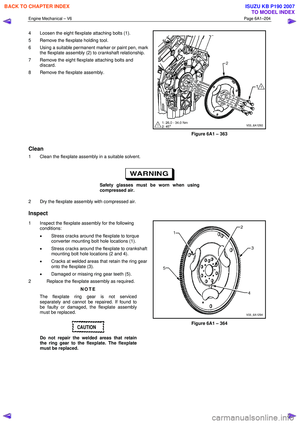
4 Loosen the eight flexplate attaching bolts (1).
5 Remove the flexplate holding tool.
6 Using a suitable permanent marker or paint pen, mark the flexplate assembly (2) to crankshaft relationship.
7 Remove the eight flexplate attaching bolts and discard.
8 Remove the flexplate assembly.
Figure 6A1 – 363
Clean
1 Clean the flexplate assembly in a suitable solvent.
Safety glasses must be worn when using
compressed air.
2 Dry the flexplate assembly with compressed air.
Inspect
1 Inspect the flexplate assembly for the following conditions:
• Stress cracks around the flexplate to torque
converter mounting bolt hole locations (1).
• Stress cracks around the flexplate to crankshaft
mounting bolt hole locations (2 and 4).
• Cracks at welded areas that retain the ring gear
onto the flexplate (3).
• Damaged or missing ring gear teeth (5).
2 Replace the flexplate assembly as required.
NOTE
The flexplate ring gear is not serviced
separately and cannot be repaired. If found to
be faulty or damaged, the flexplate assembly
must be replaced.
CAUTION
Do not repair the welded areas that retain
the ring gear to the flexplate. The flexplate
must be replaced.
Figure 6A1 – 364
BACK TO CHAPTER INDEX
TO MODEL INDEX
ISUZU KB P190 2007
Page 2693 of 6020
Engine Mechanical – V6 Page 6A1–214
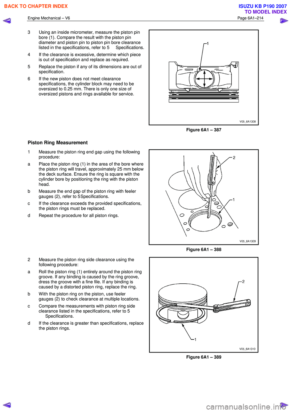
3 Using an inside micrometer, measure the piston pin
bore (1). Compare the result with the piston pin
diameter and piston pin to piston pin bore clearance
listed in the specifications, refer to 5 Specifications.
4 If the clearance is excessive, determine which piece is out of specification and replace as required.
5 Replace the piston if any of its dimensions are out of specification.
6 If the new piston does not meet clearance specifications, the cylinder block may need to be
oversized to 0.25 mm. There is only one size of
oversized pistons and rings available for service.
Figure 6A1 – 387
Piston Ring Measurement
1 Measure the piston ring end gap using the following procedure:
a Place the piston ring (1) in the area of the bore where the piston ring will travel, approximately 25 mm below
the deck surface. Ensure the ring is square with the
cylinder bore by positioning the ring with the piston
head.
b Measure the end gap of the piston ring with feeler gauges (2), refer to 5 Specifications.
c If the clearance exceeds the provided specifications, the piston rings must be replaced.
d Repeat the procedure for all piston rings.
Figure 6A1 – 388
2 Measure the piston ring side clearance using the following procedure:
a Roll the piston ring (1) entirely around the piston ring groove. If any binding is caused by the ring groove,
dress the groove with a fine file. If any binding is
caused by a distorted piston ring, replace the ring.
b W ith the piston ring on the piston, use feeler gauges (2) to check clearance at multiple locations.
c Compare the measurements with piston ring side clearance listed in the specifications, refer to 5
Specifications.
d If the clearance is greater than specifications, replace the piston rings.
Figure 6A1 – 389
BACK TO CHAPTER INDEX
TO MODEL INDEX
ISUZU KB P190 2007
Page 2694 of 6020
Engine Mechanical – V6 Page 6A1–215
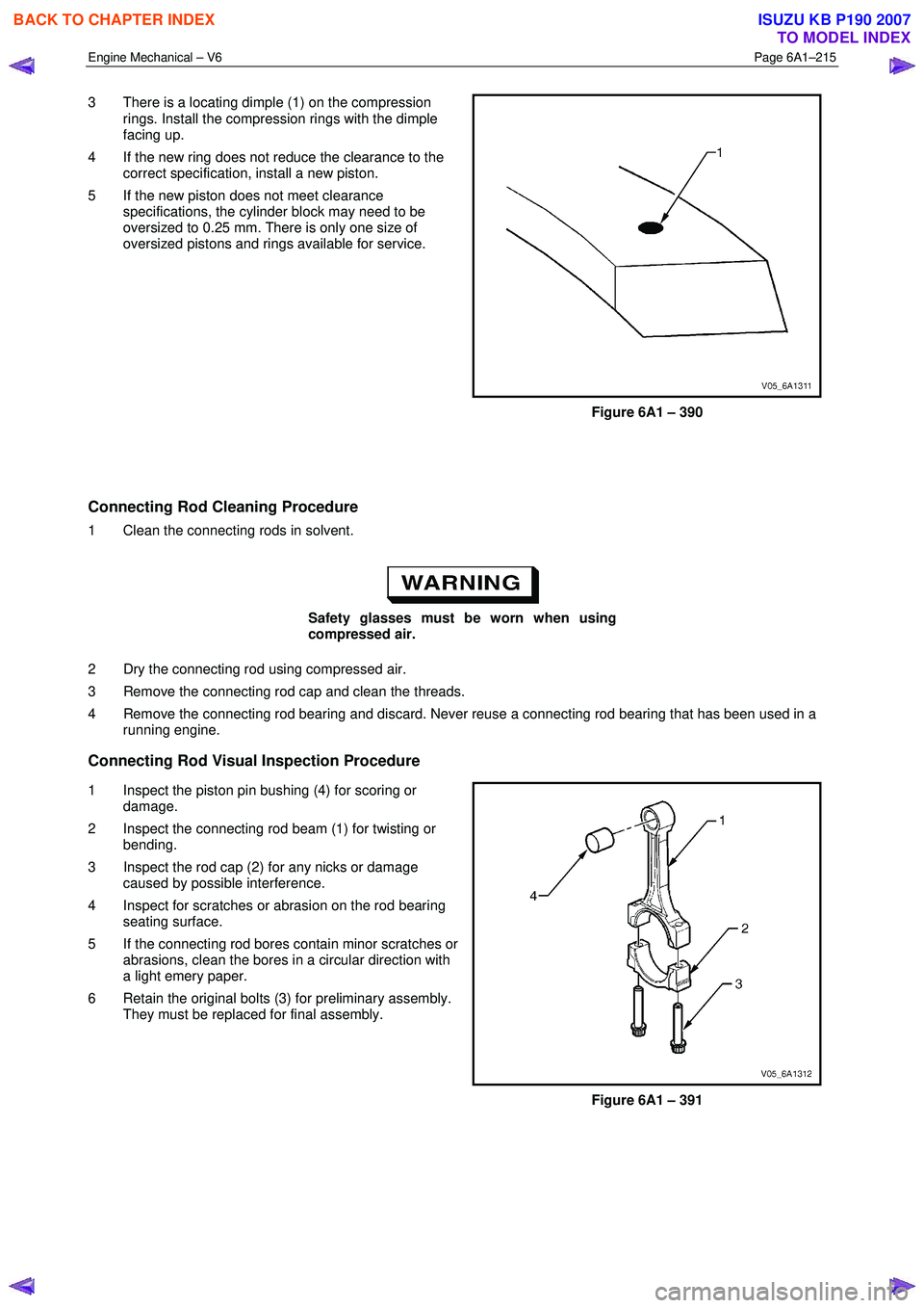
3 There is a locating dimple (1) on the compression
rings. Install the compression rings with the dimple
facing up.
4 If the new ring does not reduce the clearance to the correct specification, install a new piston.
5 If the new piston does not meet clearance specifications, the cylinder block may need to be
oversized to 0.25 mm. There is only one size of
oversized pistons and rings available for service.
Figure 6A1 – 390
Connecting Rod Cleaning Procedure
1 Clean the connecting rods in solvent.
Safety glasses must be worn when using
compressed air.
2 Dry the connecting rod using compressed air.
3 Remove the connecting rod cap and clean the threads.
4 Remove the connecting rod bearing and discard. Never reuse a connecting rod bearing that has been used in a running engine.
Connecting Rod Visual Inspection Procedure
1 Inspect the piston pin bushing (4) for scoring or
damage.
2 Inspect the connecting rod beam (1) for twisting or bending.
3 Inspect the rod cap (2) for any nicks or damage caused by possible interference.
4 Inspect for scratches or abrasion on the rod bearing seating surface.
5 If the connecting rod bores contain minor scratches or abrasions, clean the bores in a circular direction with
a light emery paper.
6 Retain the original bolts (3) for preliminary assembly. They must be replaced for final assembly.
Figure 6A1 – 391
BACK TO CHAPTER INDEX
TO MODEL INDEX
ISUZU KB P190 2007
Page 2702 of 6020
Engine Mechanical – V6 Page 6A1–223
NOTE
During and after installation, ensure each piston
is positioned correctly in the correct cylinder. The
locating arrow on the top of each piston must be
pointing toward the front of the engine.
6 Repeat these procedures for the remaining piston/connecting rod assemblies.
7 Reinstall the oil pan and oil pump pick up assembly, refer to 4.2 Oil Pan and Oil Pump Suction Pipe Assembly.
8 Reinstall the cylinder heads, refer to 3.22 Cylinder Head Assembly.
9 Reinstall the engine assembly, refer to 4.1 Engine .
4.6 Crankshaft and Main Bearings
1 Remove the engine assembly, refer to 4.1 Engine .
2 Remove both cylinder head assemblies, refer to 3.22 Cylinder Head Assembly.
3 Remove the oil pan assembly, refer to 4.2 Oil Pan and Oil Pump Suction Pipe Assembly.
4 Remove the piston and connecting rod assemblies, refer to 4.5 Pistons, Pins, Rings, Connecting Rods and Big- end Bearings.
5 Remove the oil pump assembly, refer to 3.17 Oil Pump Assembly.
6 Remove the crankshaft rear oil seal and plate assembly, refer to 4.4 Crankshaft Rear Seal and Plate Assembly.
7 Remove the crankshaft position sensor, refer to 6C1-3 Engine Management – V6 – Service Operations.
Crankshaft End Play Measurement
1 Place a dial indicator at the end of the crankshaft nose.
2 Gently force the crankshaft towards the front and rear of the cylinder block with a lever while monitoring the movement of the dial indicator.
3 The crankshaft endplay should not exceed specifications, refer to 5 Specifications.
4 If the specifications are exceeded, inspect the thrust bearing thrust outer diameter and the crankshaft thrust wall for wear and/or excessive runout. Compare the values with the specifications, refer to 5 Specifications.
5 Replace the thrust bearing or crankshaft as required.
Remove
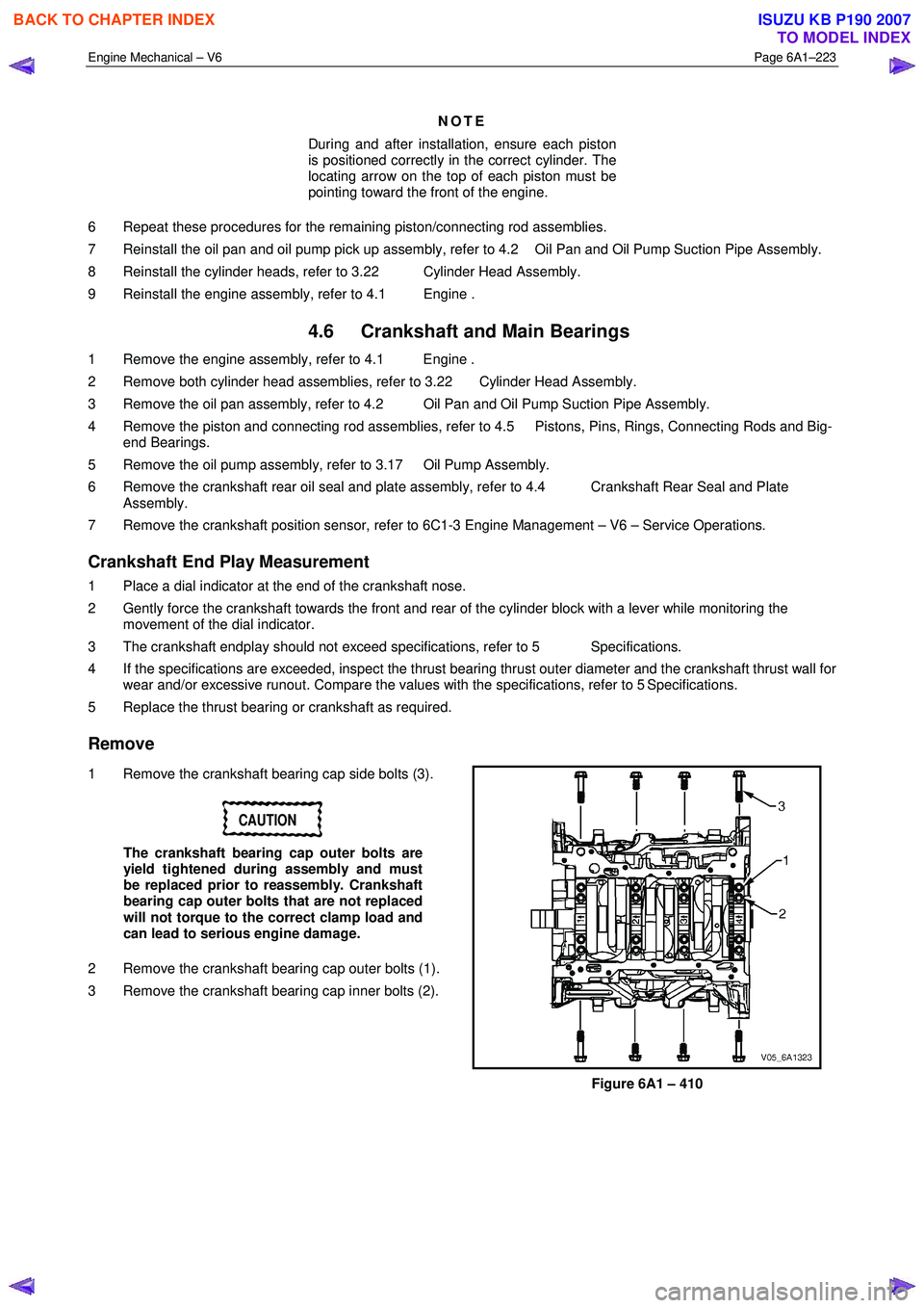
1 Remove the crankshaft bearing cap side bolts (3).
CAUTION
The crankshaft bearing cap outer bolts are
yield tightened during assembly and must
be replaced prior to reassembly. Crankshaft
bearing cap outer bolts that are not replaced
will not torque to the correct clamp load and
can lead to serious engine damage.
2 Remove the crankshaft bearing cap outer bolts (1).
3 Remove the crankshaft bearing cap inner bolts (2).
Figure 6A1 – 410
BACK TO CHAPTER INDEX
TO MODEL INDEX
ISUZU KB P190 2007
Page 2708 of 6020
Engine Mechanical – V6 Page 6A1–229
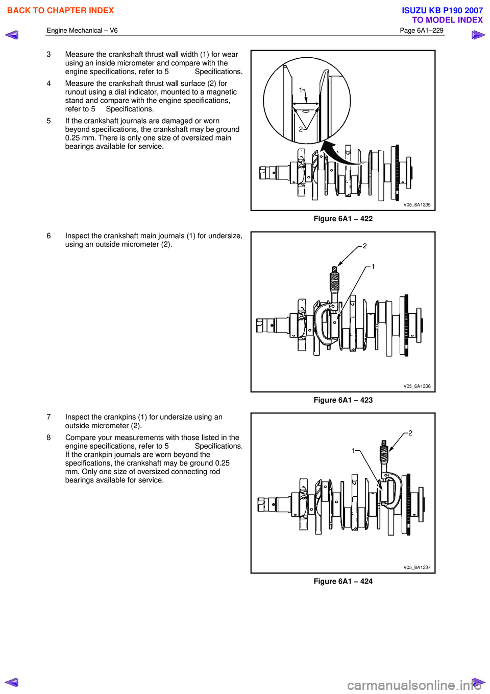
3 Measure the crankshaft thrust wall width (1) for wear
using an inside micrometer and compare with the
engine specifications, refer to 5 Specifications.
4 Measure the crankshaft thrust wall surface (2) for runout using a dial indicator, mounted to a magnetic
stand and compare with the engine specifications,
refer to 5 Specifications.
5 If the crankshaft journals are damaged or worn beyond specifications, the crankshaft may be ground
0.25 mm. There is only one size of oversized main
bearings available for service.
Figure 6A1 – 422
6 Inspect the crankshaft main journals (1) for undersize, using an outside micrometer (2).
Figure 6A1 – 423
7 Inspect the crankpins (1) for undersize using an outside micrometer (2).
8 Compare your measurements with those listed in the engine specifications, refer to 5 Specifications.
If the crankpin journals are worn beyond the
specifications, the crankshaft may be ground 0.25
mm. Only one size of oversized connecting rod
bearings available for service.
Figure 6A1 – 424
BACK TO CHAPTER INDEX
TO MODEL INDEX
ISUZU KB P190 2007
Page 2709 of 6020
Engine Mechanical – V6 Page 6A1–230
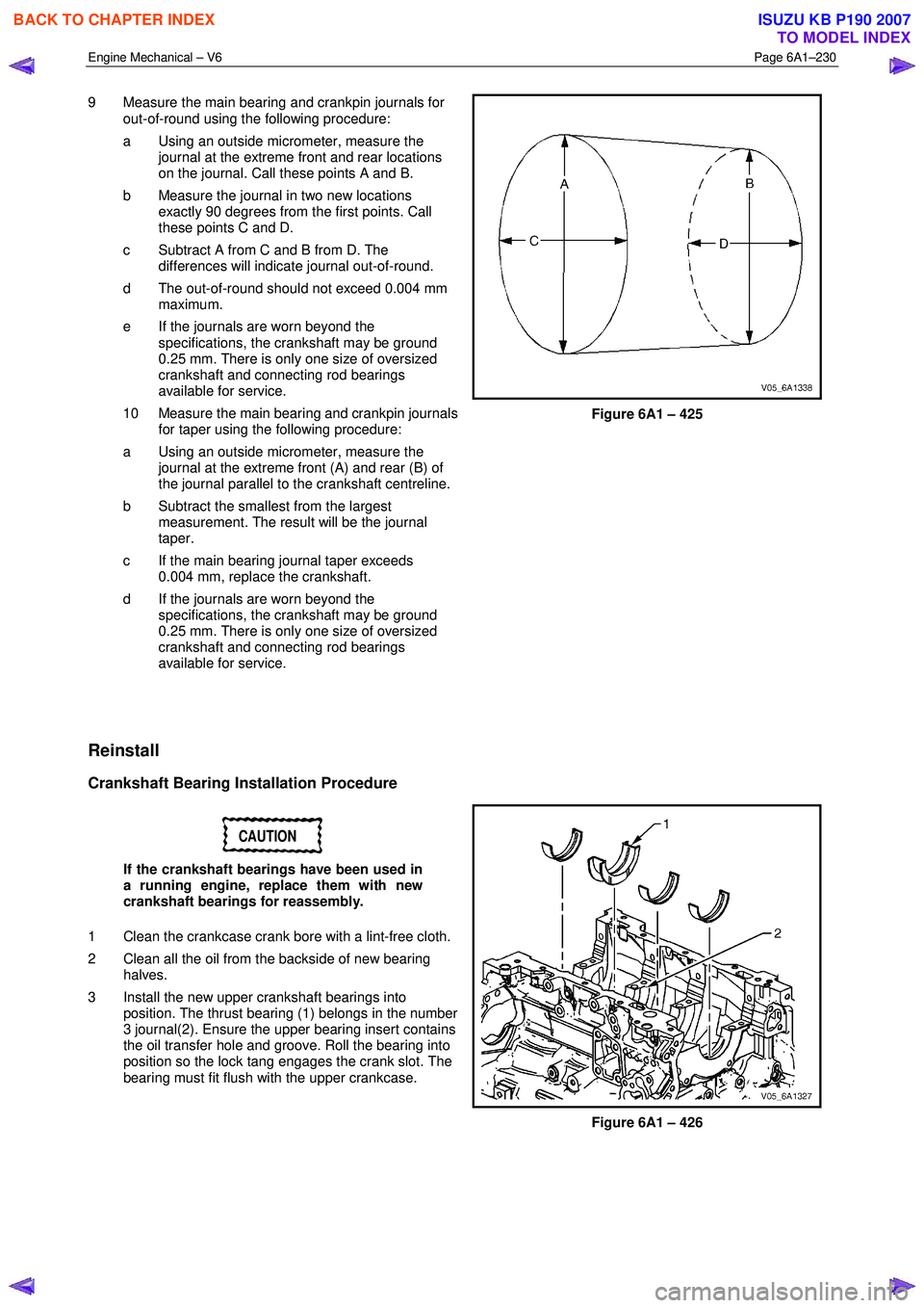
9 Measure the main bearing and crankpin journals for
out-of-round using the following procedure:
a Using an outside micrometer, measure the journal at the extreme front and rear locations
on the journal. Call these points A and B.
b Measure the journal in two new locations exactly 90 degrees from the first points. Call
these points C and D.
c Subtract A from C and B from D. The differences will indicate journal out-of-round.
d The out-of-round should not exceed 0.004 mm maximum.
e If the journals are worn beyond the specifications, the crankshaft may be ground
0.25 mm. There is only one size of oversized
crankshaft and connecting rod bearings
available for service.
10 Measure the main bearing and crankpin journals for taper using the following procedure:
a Using an outside micrometer, measure the journal at the extreme front (A) and rear (B) of
the journal parallel to the crankshaft centreline.
b Subtract the smallest from the largest measurement. The result will be the journal
taper.
c If the main bearing journal taper exceeds 0.004 mm, replace the crankshaft.
d If the journals are worn beyond the specifications, the crankshaft may be ground
0.25 mm. There is only one size of oversized
crankshaft and connecting rod bearings
available for service.
Figure 6A1 – 425
Reinstall
Crankshaft Bearing Installation Procedure
CAUTION
If the crankshaft bearings have been used in
a running engine, replace them with new
crankshaft bearings for reassembly.
1 Clean the crankcase crank bore with a lint-free cloth.
2 Clean all the oil from the backside of new bearing halves.
3 Install the new upper crankshaft bearings into position. The thrust bearing (1) belongs in the number
3 journal(2). Ensure the upper bearing insert contains
the oil transfer hole and groove. Roll the bearing into
position so the lock tang engages the crank slot. The
bearing must fit flush with the upper crankcase.
Figure 6A1 – 426
BACK TO CHAPTER INDEX
TO MODEL INDEX
ISUZU KB P190 2007
Page 2718 of 6020
Engine Mechanical – V6 Page 6A1–239
Inspect
Visual Inspection
NOTE
The following procedure assumes the engine has
been disassembled and cleaned, as described
above.
1 Inspect the crankshaft bearing journals for damage or spun bearings. The crankshaft bearing journals are not repairable and if damage is found, the cylinder block assembly must be replaced.
2 Inspect the primary camshaft chain tensioner mounting surface on the engine block for burrs or any defects that would affect the sealing of the new primary camshaft chain tensioner gasket.
3 Inspect all sealing and mating surfaces for damage, repair or replace the cylinder block assembly if required.
4 Inspect all threaded and through holes for damage or excessive debris.
5 Inspect all bolts for damage, if damaged replace with new bolts only.
6 Inspect the cylinder walls for cracks or damage. The cylinder sleeves are not serviced separately, if the cylinders are damaged the cylinder block assembly must be replaced.
7 Inspect the engine block for cracks. Do not repair any cracks. If cracks are found, the cylinder block assembly must be replaced. Repair any damaged threaded holes, refer to 4.9 Thread Repair Specifications.
Measuring Cylinder Bore Diameter
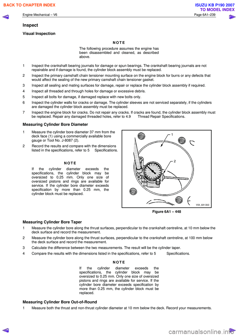
1 Measure the cylinder bore diameter 37 mm from the deck face (1) using a commercially available bore
gauge or Tool No. J-8087 (2).
2 Record the results and compare with the dimensions listed in the specifications, refer to 5 Specifications.
NOTE
If the cylinder diameter exceeds the
specifications, the cylinder block may be
oversized to 0.25 mm. Only one size of
oversized pistons and rings are available for
service. If the cylinder bore diameter exceeds
specification by more than 0.25 mm, the
cylinder block must be replaced.
Figure 6A1 – 448
Measuring Cylinder Bore Taper
1 Measure the cylinder bore along the thrust surfaces, perpendicular to the crankshaft centreline, at 10 mm below the deck surface and record the measurement.
2 Measure the cylinder bore along the thrust surfaces, perpendicular to the crankshaft centreline, at 100 mm below the deck surface and record the measurement.
3 Calculate the difference between the two measurements. The result will be the cylinder taper.
4 Compare the results with the dimensions listed in the specifications, refer to 5 Specifications.
NOTE
If the cylinder diameter exceeds the
specifications, the cylinder block may be
oversized to 0.25 mm. Only one size of oversized
pistons and rings are available for service. If the
cylinder bore diameter exceeds specification by
more than 0.25 mm, the cylinder block must be
replaced.
Measuring Cylinder Bore Out-of-Round
1 Measure both the thrust and non-thrust cylinder diameter at 10 mm below the deck. Record your measurements.
BACK TO CHAPTER INDEX
TO MODEL INDEX
ISUZU KB P190 2007