2007 ISUZU KB P190 service
[x] Cancel search: servicePage 2803 of 6020
Engine Mechanical – V6 Page 6A1–26
Page 6A1–26
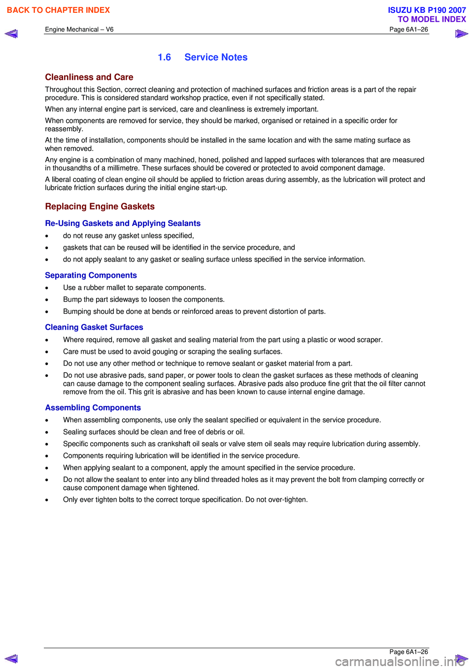
1.6 Service Notes
Cleanliness and Care
Throughout this Section, correct cleaning and protection of machined surfaces and fr iction areas is a part of the repair
procedure. This is considered standard workshop practice, even if not specifically stated.
When any internal engine part is serviced, care and cleanliness is extremely important.
When components are removed for service, they should be ma rked, organised or retained in a specific order for
reassembly.
At the time of installation, components should be installed in the same location and with the same mating surface as
when removed.
Any engine is a combination of many machined, honed, polished and lapped surfaces with tole rances that are measured
in thousandths of a millimetre. Thes e surfaces should be covered or protected to avoid component damage.
A liberal coating of clean engine oil should be applied to fricti on areas during assembly, as the lubrication will protect and
lubricate friction surfaces dur ing the initial engine start-up.
Replacing Engine Gaskets
Re-Using Gaskets and Applying Sealants
• do not reuse any gasket unless specified,
• gaskets that can be reused will be ident ified in the service procedure, and
• do not apply sealant to any gasket or sealing surf ace unless specified in the service information.
Separating Components
• Use a rubber mallet to separate components.
• Bump the part sideways to loosen the components.
• Bumping should be done at bends or reinforced areas to prevent distortion of parts.
Cleaning Gasket Surfaces
• Where required, remove all gasket and sealing materi al from the part using a plastic or wood scraper.
• Care must be used to avoid gouging or scraping the sealing surfaces.
• Do not use any other method or technique to re move sealant or gasket material from a part.
• Do not use abrasive pads, sand paper, or power tools to clean the gasket surfaces as these methods of cleaning
can cause damage to the component sealing surfaces. Abrasive pads also produce fine grit that the oil filter cannot
remove from the oil. This grit is abrasiv e and has been known to cause internal engine damage.
Assembling Components
• When assembling components, use only the sealant specified or equivalent in the service procedure.
• Sealing surfaces should be cl ean and free of debris or oil.
• Specific components such as crankshaft oil seals or valve stem oil seals may require lubrication during assembly.
• Components requiring lubrication will be i dentified in the service procedure.
• When applying sealant to a component, apply the am ount specified in the service procedure.
• Do not allow the sealant to enter into any blind threaded hol es as it may prevent the bolt from clamping correctly or
cause component damage when tightened.
• Only ever tighten bolts to the correct to rque specification. Do not over-tighten.
BACK TO CHAPTER INDEX
TO MODEL INDEX
ISUZU KB P190 2007
Page 2804 of 6020
Engine Mechanical – V6 Page 6A1–27
Page 6A1–27
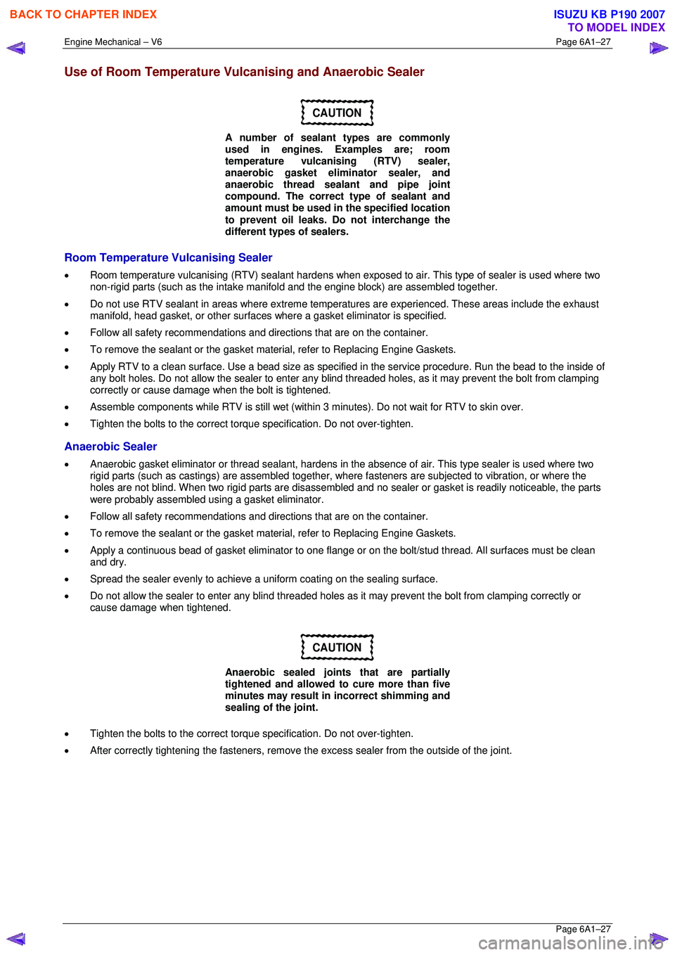
Use of Room Temperature Vulcanising and Anaerobic Sealer
CAUTION
A number of sealant types are commonly
used in engines. Examples are; room
temperature vulcanising (RTV) sealer,
anaerobic gasket eliminator sealer, and
anaerobic thread sealant and pipe joint
compound. The correct type of sealant and
amount must be used in the specified location
to prevent oil leaks. Do not interchange the
different types of sealers.
Room Temperature Vulcanising Sealer
• Room temperature vulcanising (RTV) s ealant hardens when exposed to air. This type of sealer is used where two
non-rigid parts (such as the intake manifold and the engine block) are assembled together.
• Do not use RTV sealant in areas where extreme temper atures are experienced. These areas include the exhaust
manifold, head gasket, or other surfaces w here a gasket eliminator is specified.
• Follow all safety recommendations and di rections that are on the container.
• To remove the sealant or the gasket mate rial, refer to Replacing Engine Gaskets.
• Apply RTV to a clean surface. Use a bead size as specified in the service procedure. Run the bead to the inside of
any bolt holes. Do not allow the sealer to enter any bli nd threaded holes, as it may prevent the bolt from clamping
correctly or cause damage when the bolt is tightened.
• Assemble components while RTV is still wet (within 3 minutes). Do not wait for RTV to skin over.
• Tighten the bolts to the correct torque specification. Do not over-tighten.
Anaerobic Sealer
• Anaerobic gasket eliminator or thread sealant, hardens in t he absence of air. This type sealer is used where two
rigid parts (such as castings) are assembled together, w here fasteners are subjected to vibration, or where the
holes are not blind. When two rigid parts are disassembled and no sealer or gasket is readily noticeable, the parts
were probably assembled using a gasket eliminator.
• Follow all safety recommendations and di rections that are on the container.
• To remove the sealant or the gasket mate rial, refer to Replacing Engine Gaskets.
• Apply a continuous bead of gasket eliminator to one flange or on the bolt/stud thread. All surfaces must be clean
and dry.
• Spread the sealer evenly to achieve a uniform coating on the sealing surface.
• Do not allow the sealer to enter any blind threaded holes as it may prevent the bolt from clamping correctly or
cause damage when tightened.
CAUTION
Anaerobic sealed joints that are partially
tightened and allowed to cure more than five
minutes may result in incorrect shimming and
sealing of the joint.
• Tighten the bolts to the correct torque specification. Do not over-tighten.
• After correctly tightening the fasteners, remove t he excess sealer from the outside of the joint.
BACK TO CHAPTER INDEX
TO MODEL INDEX
ISUZU KB P190 2007
Page 2805 of 6020
Engine Mechanical – V6 Page 6A1–28
Page 6A1–28
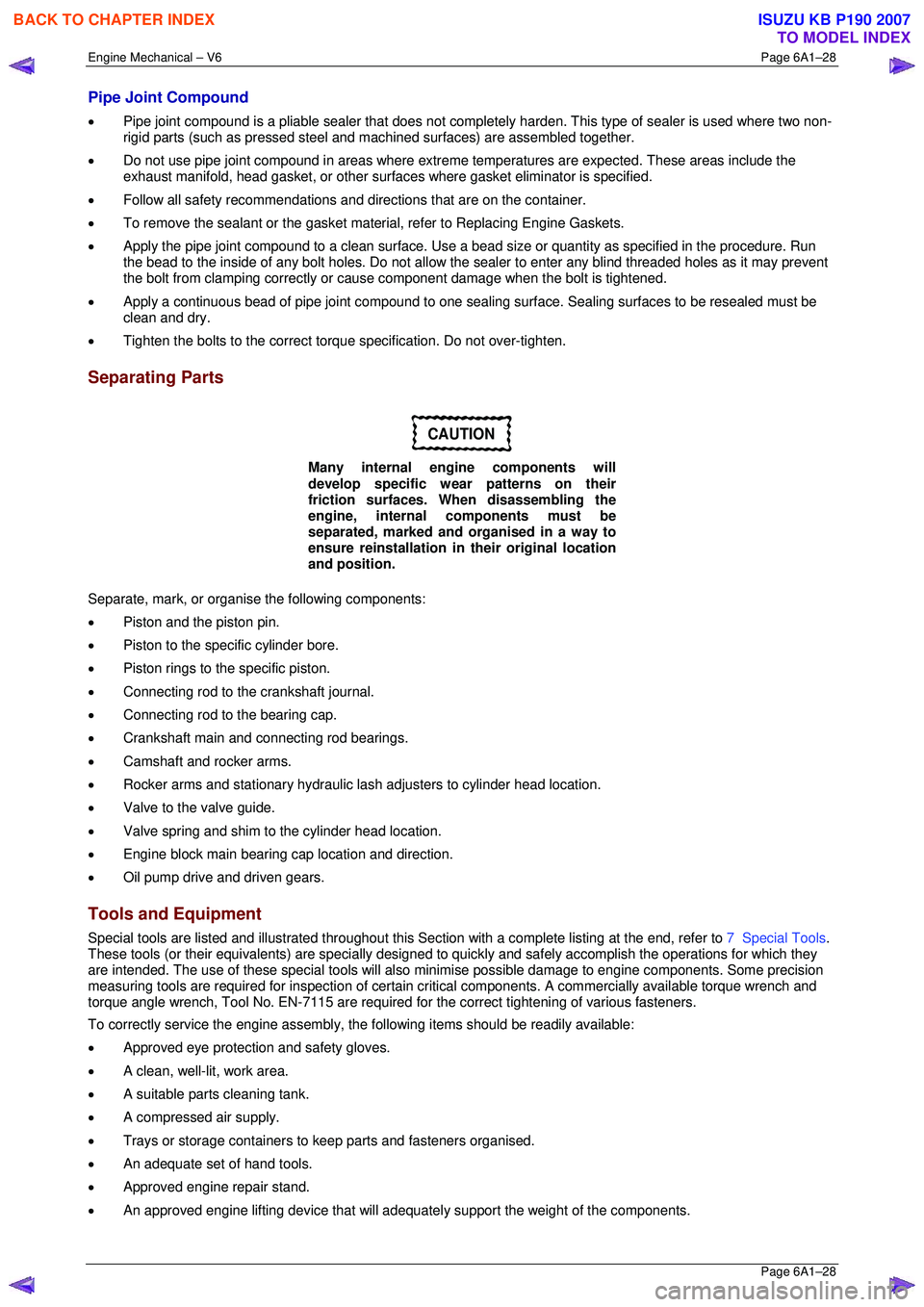
Pipe Joint Compound
• Pipe joint compound is a pliable sealer that does not comp letely harden. This type of sealer is used where two non-
rigid parts (such as pressed steel and ma chined surfaces) are assembled together.
• Do not use pipe joint compound in areas where extreme temperatures are expected. These areas include the
exhaust manifold, head gasket, or other surfaces where gasket eliminator is specified.
• Follow all safety recommendations and di rections that are on the container.
• To remove the sealant or the gasket mate rial, refer to Replacing Engine Gaskets.
• Apply the pipe joint compound to a clean surface. Use a bead size or quantity as specified in the procedure. Run
the bead to the inside of any bolt holes. Do not allow the s ealer to enter any blind threaded holes as it may prevent
the bolt from clamping correctly or caus e component damage when the bolt is tightened.
• Apply a continuous bead of pipe joint compound to one seali ng surface. Sealing surfaces to be resealed must be
clean and dry.
• Tighten the bolts to the correct torque specification. Do not over-tighten.
Separating Parts
CAUTION
Many internal engine components will
develop specific wear patterns on their
friction surfaces. When disassembling the
engine, internal components must be
separated, marked and organised in a way to
ensure reinstallation in their original location
and position.
Separate, mark, or organise the following components:
• Piston and the piston pin.
• Piston to the specific cylinder bore.
• Piston rings to the specific piston.
• Connecting rod to the crankshaft journal.
• Connecting rod to the bearing cap.
• Crankshaft main and connecting rod bearings.
• Camshaft and rocker arms.
• Rocker arms and stationary hydraulic lash adjusters to cylinder head location.
• Valve to the valve guide.
• Valve spring and shim to the cylinder head location.
• Engine block main bearing cap location and direction.
• Oil pump drive and driven gears.
Tools and Equipment
Special tools are listed and illustrated throughout this Section with a complete listing at the end, refer to 7 Special Tools.
These tools (or their equivalents) are specially designed to quickly and safely accomplish the operations for which they
are intended. The use of these special tools will also minimise possible damage to engine components. Some precision
measuring tools are required for inspec tion of certain critical components. A commercially available torque wrench and
torque angle wrench, Tool No. EN-7115 are required for the correct tightening of various fasteners.
To correctly service the engine assembly, the following items should be readily available:
• Approved eye protection and safety gloves.
• A clean, well-lit, work area.
• A suitable parts cleaning tank.
• A compressed air supply.
• Trays or storage containers to keep parts and fasteners organised.
• An adequate set of hand tools.
• Approved engine repair stand.
• An approved engine lifting device that will adequatel y support the weight of the components.
BACK TO CHAPTER INDEX
TO MODEL INDEX
ISUZU KB P190 2007
Page 2809 of 6020
Engine Mechanical – V6 Page 6A1–32
Page 6A1–32
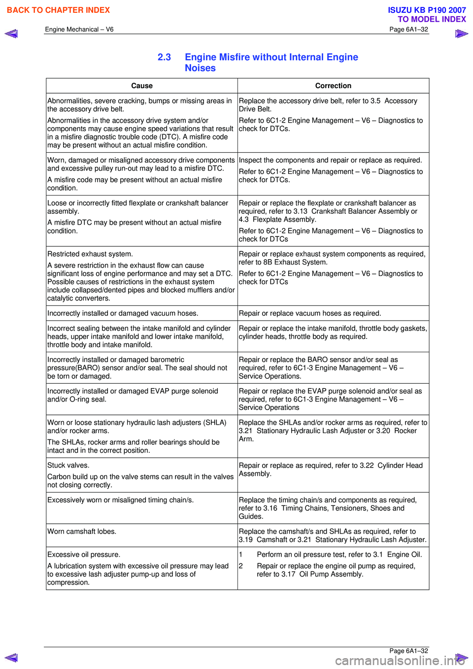
2.3 Engine Misfire without Internal Engine
Noises
Cause Correction
Abnormalities, severe cracking, bumps or missing areas in
the accessory drive belt.
Abnormalities in the accessory drive system and/or
components may cause engine speed variations that result
in a misfire diagnostic trouble code (DTC). A misfire code
may be present without an ac tual misfire condition. Replace the accessory drive belt, refer to 3.5 Accessory
Drive Belt.
Refer to 6C1-2 Engine Management – V6 – Diagnostics to
check for DTCs.
Worn, damaged or misaligned accessory drive components
and excessive pulley run-out may lead to a misfire DTC.
A misfire code may be present without an actual misfire
condition. Inspect the components and repair or replace as required.
Refer to 6C1-2 Engine Management – V6 – Diagnostics to
check for DTCs.
Loose or incorrectly fitted flexplate or crankshaft balancer
assembly.
A misfire DTC may be present without an actual misfire
condition. Repair or replace the flexplat
e or crankshaft balancer as
required, refer to 3.13 Crankshaft Balancer Assembly or
4.3 Flexplate Assembly.
Refer to 6C1-2 Engine Management – V6 – Diagnostics to
check for DTCs
Restricted exhaust system.
A severe restriction in the exhaust flow can cause
significant loss of engine performance and may set a DTC.
Possible causes of restrict ions in the exhaust system
include collapsed/dented pipes and blocked mufflers and/or
catalytic converters. Repair or replace exhaust syst
em components as required,
refer to 8B Exhaust System.
Refer to 6C1-2 Engine Management – V6 – Diagnostics to
check for DTCs
Incorrectly installed or damaged vacuum hoses. Repair or replace vacuum hoses as required.
Incorrect sealing between the intake manifold and cylinder
heads, upper intake manifold and lower intake manifold,
throttle body and intake manifold. Repair or replace the intake
manifold, throttle body gaskets,
cylinder heads, throttle body as required.
Incorrectly installed or damaged barometric
pressure(BARO) sensor and/or seal. The seal should not
be torn or damaged. Repair or replace the BARO sensor and/or seal as
required, refer to 6C1-3 Engine Management – V6 –
Service Operations.
Incorrectly installed or damaged EVAP purge solenoid
and/or O-ring seal. Repair or replace the EVAP purge solenoid and/or seal as
required, refer to 6C1-3 Engine Management – V6 –
Service Operations
Worn or loose stationary hydraulic lash adjusters (SHLA)
and/or rocker arms.
The SHLAs, rocker arms and roller bearings should be
intact and in the correct position. Replace the SHLAs and/or rocker arms as required, refer to
3.21 Stationary Hydraulic Las h Adjuster or 3.20 Rocker
Arm.
Stuck valves.
Carbon build up on the valve stem s can result in the valves
not closing correctly. Repair or replace as required, refer to 3.22 Cylinder Head
Assembly.
Excessively worn or misaligned timing chain/s. Replace the timing chain/s and components as required,
refer to 3.16 Timing Chains, Tensioners, Shoes and
Guides.
Worn camshaft lobes. Replace the camshaft/s and SHLAs as required, refer to
3.19 Camshaft or 3.21 Stati onary Hydraulic Lash Adjuster.
Excessive oil pressure.
A lubrication system with ex cessive oil pressure may lead
to excessive lash adjuster pump-up and loss of
compression. 1 Perform an oil pressure tes
t, refer to 3.1 Engine Oil.
2 Repair or replace the engine oil pump as required, refer to 3.17 Oil Pump Assembly.
BACK TO CHAPTER INDEX
TO MODEL INDEX
ISUZU KB P190 2007
Page 2810 of 6020
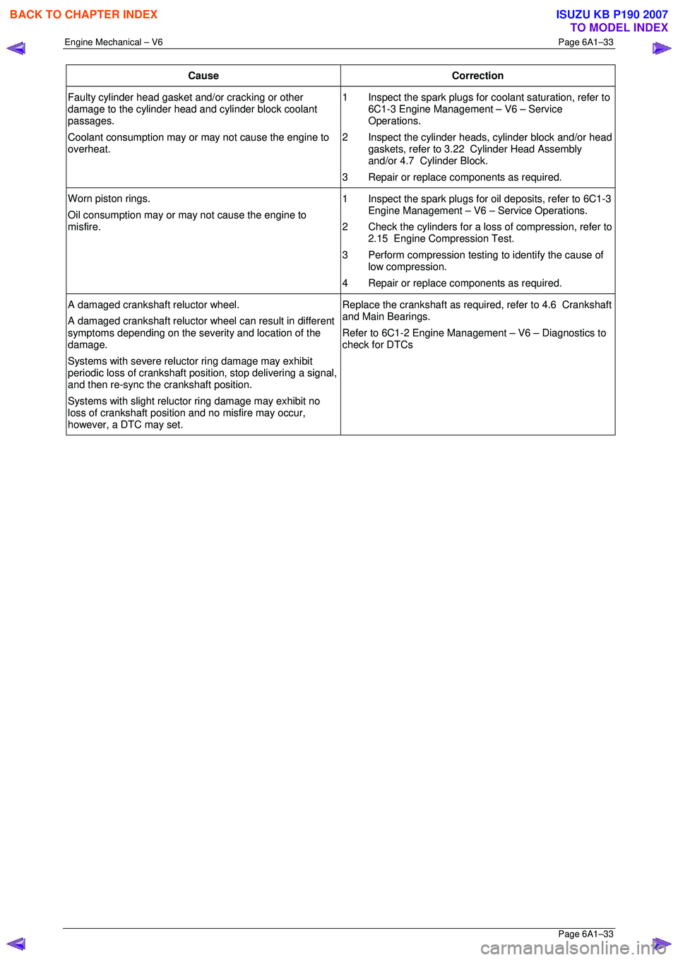
Engine Mechanical – V6 Page 6A1–33
Page 6A1–33
Cause Correction
Faulty cylinder head gasket and/or cracking or other
damage to the cylinder head and cylinder block coolant
passages.
Coolant consumption may or may not cause the engine to
overheat. 1 Inspect the spark plugs for
coolant saturation, refer to
6C1-3 Engine Management – V6 – Service
Operations.
2 Inspect the cylinder heads, cylinder block and/or head gaskets, refer to 3.22 Cylinder Head Assembly
and/or 4.7 Cylinder Block.
3 Repair or replace components as required.
Worn piston rings.
Oil consumption may or ma y not cause the engine to
misfire. 1 Inspect the spark plugs for oil deposits, refer to 6C1-3
Engine Management – V6 – Service Operations.
2 Check the cylinders for a loss of compression, refer to 2.15 Engine Compression Test.
3 Perform compression testing to identify the cause of
low compression.
4 Repair or replace components as required.
A damaged crankshaft reluctor wheel.
A damaged crankshaft reluctor wheel can result in different
symptoms depending on the severity and location of the
damage.
Systems with severe relu ctor ring damage may exhibit
periodic loss of crankshaft posit ion, stop delivering a signal,
and then re-sync the crankshaft position.
Systems with slight reluctor ring damage may exhibit no
loss of crankshaft position and no misfire may occur,
however, a DTC may set. Replace the crankshaft as required, refer to 4.6 Crankshaft
and Main Bearings.
Refer to 6C1-2 Engine Management – V6 – Diagnostics to
check for DTCs
BACK TO CHAPTER INDEX
TO MODEL INDEX
ISUZU KB P190 2007
Page 2811 of 6020
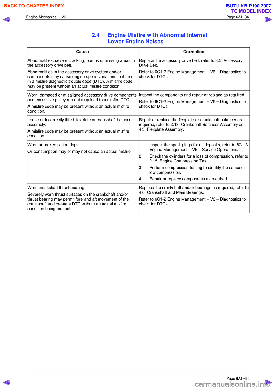
Engine Mechanical – V6 Page 6A1–34
Page 6A1–34
2.4 Engine Misfire with Abnormal Internal
Lower Engine Noises
Cause Correction
Abnormalities, severe cracking, bumps or missing areas in
the accessory drive belt.
Abnormalities in the accessory drive system and/or
components may cause engine speed variations that result
in a misfire diagnostic trouble code (DTC). A misfire code
may be present without an ac tual misfire condition. Replace the accessory drive belt, refer to 3.5 Accessory
Drive Belt.
Refer to 6C1-2 Engine Management – V6 – Diagnostics to
check for DTCs
Worn, damaged or misaligned accessory drive components
and excessive pulley run-out may lead to a misfire DTC.
A misfire code may be present without an actual misfire
condition. Inspect the components and repair or replace as required.
Refer to 6C1-2 Engine Management – V6 – Diagnostics to
check for DTCs
Loose or Incorrectly fitted flexplate or crankshaft balancer
assembly.
A misfire code may be present without an actual misfire
condition. Repair or replace the flexplat
e or crankshaft balancer as
required, refer to 3.13 Crankshaft Balancer Assembly or
4.3 Flexplate Assembly.
Worn or broken piston rings.
Oil consumption may or may not cause an actual misfire. 1 Inspect the spark plugs for oil deposits, refer to 6C1-3
Engine Management – V6 – Service Operations.
2 Check the cylinders for a loss of compression, refer to 2.15 Engine Compression Test.
3 Perform compression testing to identify the cause of
low compression.
4 Repair or replace components as required.
Worn crankshaft thrust bearing.
Severely worn thrust surfaces on the crankshaft and/or
thrust bearing may permit fore and aft movement of the
crankshaft and create a DTC wi thout an actual misfire
condition being present. Replace the crankshaft and/or bear
ings as required, refer to
4.6 Crankshaft and Main Bearings.
Refer to 6C1-2 Engine Management – V6 – Diagnostics to
check for DTCs
BACK TO CHAPTER INDEX
TO MODEL INDEX
ISUZU KB P190 2007
Page 2813 of 6020
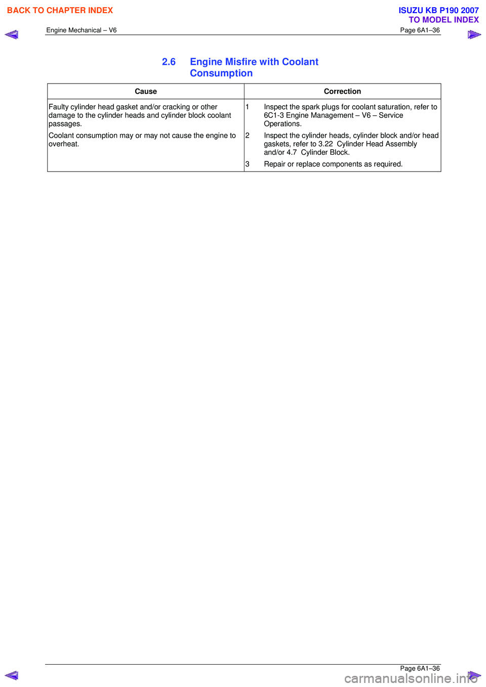
Engine Mechanical – V6 Page 6A1–36
Page 6A1–36
2.6 Engine Misfire with Coolant
Consumption
Cause Correction
Faulty cylinder head gasket and/or cracking or other
damage to the cylinder heads and cylinder block coolant
passages.
Coolant consumption may or may not cause the engine to
overheat. 1 Inspect the spark plugs for
coolant saturation, refer to
6C1-3 Engine Management – V6 – Service
Operations.
2 Inspect the cylinder heads, cylinder block and/or head gaskets, refer to 3.22 Cylinder Head Assembly
and/or 4.7 Cylinder Block.
3 Repair or replace components as required.
BACK TO CHAPTER INDEX
TO MODEL INDEX
ISUZU KB P190 2007
Page 2814 of 6020
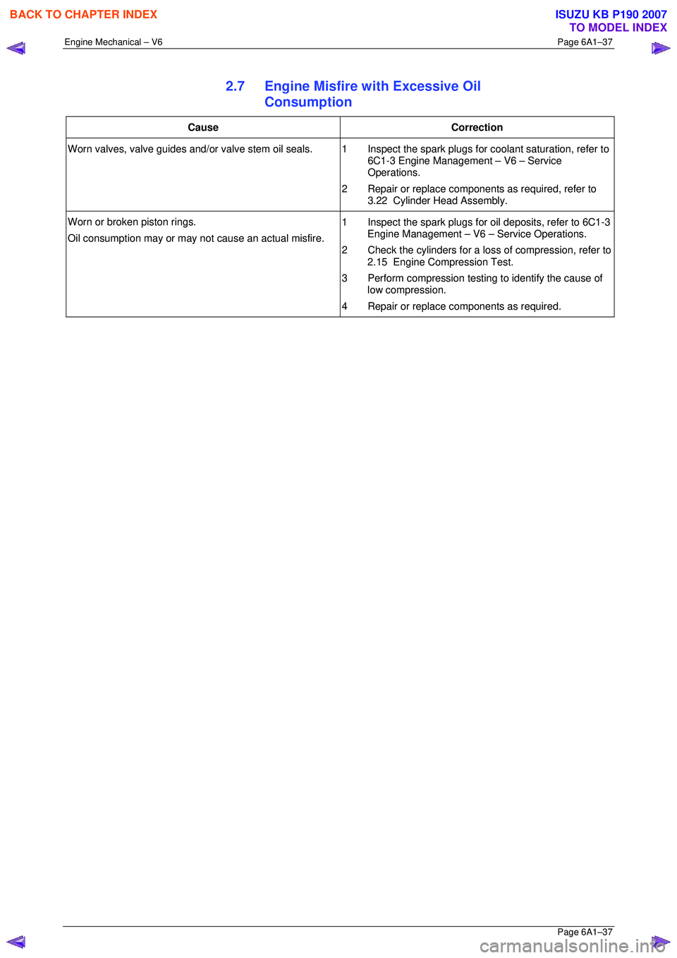
Engine Mechanical – V6 Page 6A1–37
Page 6A1–37
2.7 Engine Misfire with Excessive Oil
Consumption
Cause Correction
Worn valves, valve guides and/or valve stem oil seals. 1 Inspect the spark plugs for coolant saturation, refer to
6C1-3 Engine Management – V6 – Service
Operations.
2 Repair or replace components as required, refer to 3.22 Cylinder Head Assembly.
Worn or broken piston rings.
Oil consumption may or may not cause an actual misfire. 1 Inspect the spark plugs for oil deposits, refer to 6C1-3
Engine Management – V6 – Service Operations.
2 Check the cylinders for a loss of compression, refer to 2.15 Engine Compression Test.
3 Perform compression testing to identify the cause of
low compression.
4 Repair or replace components as required.
BACK TO CHAPTER INDEX
TO MODEL INDEX
ISUZU KB P190 2007