2007 ISUZU KB P190 service
[x] Cancel search: servicePage 2482 of 6020
Engine Mechanical – V6 Page 6A1–3
Definition .......................................................................................................................................................... 50
Diagnostic Aids................................................................................................................................................. 50
Test Description ............................................................................................................... ................................ 50
Diagnostic Table............................................................................................................................................... 51
Drive Belt Excessive Wear ...................................................................................................... ............................ 51
Definition .......................................................................................................................................................... 51
Diagnostic Aids................................................................................................................................................. 52
Test Description ............................................................................................................... ................................ 52
Diagnostic Table............................................................................................................................................... 52
Accessory Drive Belt Tensioner Diagnosis ....................................................................................... ................ 52
Diagnostic Table............................................................................................................................................... 52
3 Minor Service Operations ....................................................................................................... .............53
3.1 Engine Oil ............................................................................................................................................................. 54
Check .................................................................................................................................................................... 54
Replace ........................................................................................................................ ......................................... 54
Pressure Check ................................................................................................................. ................................... 55
3.2 Oil Filter Cartridge ............................................................................................................................................... 56
Replace ................................................................................................................................................................. 56
3.3 Oil Filter Adaptor............................................................................................................. ..................................... 57
Remove ................................................................................................................................................................. 57
Reinstall ................................................................................................................................................................ 57
3.4 Oil Level Indicator Tube ....................................................................................................... ............................... 58
Remove ............................................................................................................................................................ 58
Reinstall ........................................................................................................................................................... 58
3.5 Accessory Drive Belt ........................................................................................................... ................................ 59
RWD Vehicle ......................................................................................................................................................... 59
Remove ............................................................................................................................................................ 59
Reinstall ........................................................................................................................................................... 59
3.6 Accessory Drive Belt Idler Pulley .............................................................................................. ......................... 60
Remove ............................................................................................................................................................ 60
Reinstall ........................................................................................................................................................... 60
3.7 Accessory Drive Belt Tensioner Assembly ........................................................................................ ............... 61
Remove ............................................................................................................................................................ 61
Reinstall ........................................................................................................................................................... 61
3.8 Power Steering Pump Bracket .................................................................................................... ........................ 62
Remove ................................................................................................................................................................. 62
Reinstall ................................................................................................................................................................ 62
3.9 Upper Intake Manifold.......................................................................................................... ................................ 62
Remove ................................................................................................................................................................. 63
Disassemble ......................................................................................................................................................... 66
Clean ..................................................................................................................................................................... 66
Inspect .................................................................................................................................................................. 66
Reassemble .......................................................................................................................................................... 67
Reinstall ...................................................................................................................... .......................................... 67
3.10 Intake Manifold Assembly – Complete............................................................................................ ................... 68
Remove ................................................................................................................................................................. 68
Disassemble ......................................................................................................................................................... 72
Clean ..................................................................................................................................................................... 73
Inspect .................................................................................................................................................................. 73
Reassemble .......................................................................................................................................................... 74
Reinstall ...................................................................................................................... .......................................... 74
3.11 Exhaust Manifold Assembly ...................................................................................................... ......................... 75
Remove ................................................................................................................................................................. 75
Inspect .................................................................................................................................................................. 77
Reinstall ................................................................................................................................................................ 77
3.12 Camshaft Cover ................................................................................................................. .................................. 79
Remove ................................................................................................................................................................. 79
Clean and Inspect .............................................................................................................. .................................. 81
BACK TO CHAPTER INDEX
TO MODEL INDEX
ISUZU KB P190 2007
Page 2484 of 6020
Engine Mechanical – V6 Page 6A1–5
Camshaft Visual Inspection ............................................................................................................................ 150
Camshaft Measurement ........................................................................................................... ...................... 151
Reinstall .............................................................................................................................................................. 153
Right-hand Side................................................................................................................ .............................. 153
Left-hand Side ................................................................................................................................................ 155
3.20 Rocker Arm..................................................................................................................... .................................... 158
Remove ............................................................................................................................................................... 158
Clean and Inspect .............................................................................................................. ................................ 158
Reinstall .............................................................................................................................................................. 159
3.21 Stationary Hydraulic Lash Adjuster ............................................................................................. .................... 160
Remove ............................................................................................................................................................... 160
Clean and Inspect .............................................................................................................. ................................ 160
Reinstall .............................................................................................................................................................. 161
3.22 Cylinder Head Assembly ......................................................................................................... .......................... 161
Remove ............................................................................................................................................................... 161
Right-hand Side (Bank 1) Cylinder Head ......................................................................................... .............. 161
Left-hand Side (Bank 2) Cylinder Head .......................................................................................................... 162
Disassemble ....................................................................................................................................................... 163
Clean ................................................................................................................................................................... 166
Inspect ................................................................................................................................................................ 167
Visual Inspection .............................................................................................................. .............................. 167
Cylinder Head Measurement...................................................................................................... .................... 167
Valve Spring Inspection and Measurement ........................................................................................ ............ 169
Valve and Seat Grinding ................................................................................................................................ 170
Assemble ............................................................................................................................................................ 174
Reinstall .............................................................................................................................................................. 177
Right-hand Side (Bank 1) Cylinder Head ......................................................................................... .............. 177
Left-hand Side (Bank 2) Cylinder Head .......................................................................................................... 178
3.23 Engine Mounts and Brackets ............................................................................................................................ 181
Remove .......................................................................................................................................................... 181
Engine Mount Location .......................................................................................................... ........................... 182
Inspect ................................................................................................................................................................ 182
Reinstall .............................................................................................................................................................. 183
4 Major Service Operations ....................................................................................................... ...........184
4.1 Engine Removal ................................................................................................................................................. 184
Remove .......................................................................................................................................................... 185
Disassemble................................................................................................................................................... 197
Reassemble ................................................................................................................................................... 198
Reinstall ......................................................................................................................................................... 198
4.2 Oil Pan and Oil Pump Suction Pipe Assembly ..................................................................................... ........... 198
Remove .......................................................................................................................................................... 198
Disassemble................................................................................................................................................... 200
Clean .............................................................................................................................................................. 200
Inspect............................................................................................................................................................ 201
Reassemble ................................................................................................................................................... 201
Reinstall ......................................................................................................................................................... 202
4.3 Flexplate Assembly ............................................................................................................. .............................. 203
Remove ............................................................................................................................................................... 203
Clean ................................................................................................................................................................... 204
Inspect ................................................................................................................................................................ 204
Reinstall ...................................................................................................................... ........................................ 205
4.4 Crankshaft Rear Seal and Plate Assembly ........................................................................................ .............. 205
Remove ............................................................................................................................................................... 205
Reinstall .............................................................................................................................................................. 207
4.5 Pistons, Pins, Rings, Connecting Rods and Big-end Bearings ..................................................................... 208
Remove ............................................................................................................................................................... 208
Disassemble ....................................................................................................................................................... 211
Clean and Inspect .............................................................................................................. ................................ 212
BACK TO CHAPTER INDEX
TO MODEL INDEX
ISUZU KB P190 2007
Page 2487 of 6020
Engine Mechanical – V6 Page 6A1–8
1 General Information
The HFV6 engine features a closed vee, deep skirt die cast aluminium cylinder block with cast iron cylinder liners,
internally balanced crankcase, full length water jackets and six bolt main bearing caps.
The cylinders are arranged in two banks of three with a 60 degree included angle between the two banks.
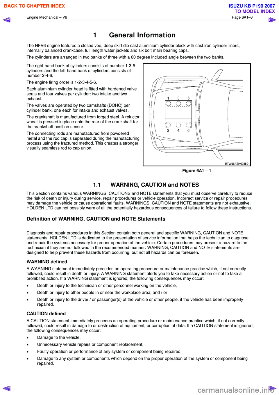
The right-hand bank of cylinders consists of number 1-3-5
cylinders and the left-hand bank of cylinders consists of
number 2-4-6.
The engine firing order is 1-2-3-4-5-6.
Each aluminium cylinder head is fitted with hardened valve
seats and four valves per cylinder: two intake and two
exhaust.
The valves are operated by two camshafts (DOHC) per
cylinder bank, one each for intake and exhaust valves.
The crankshaft is manufactured from forged steel. A reluctor
wheel is pressed in place onto the rear of the crankshaft for
the crankshaft position sensor.
The connecting rods are manufactured from powdered
metal and the rod cap is separated during the manufacturing
process using the fractured method. This creates a stronger,
visually seamless rod to cap union.
Figure 6A1 – 1
1.1 WARNING, CAUTION and NOTES
This Section contains various W ARNINGS, CAUTIONS and NOTE statements that you must observe carefully to reduce
the risk of death or injury during service, repair procedures or vehicle operation. Incorrect service or repair procedures
may damage the vehicle or cause operational faults. W ARNINGS, CAUTION and NOTE statements are not exhaustive.
HOLDEN LTD can not possibly warn of all the potentially hazardous consequences of failure to follow these instructions.
Definition of WARNING, CAUTION and NOTE Statements
Diagnosis and repair procedures in this Section contain both general and specific W ARNING, CAUTION and NOTE
statements. HOLDEN LTD is dedicated to the presentation of service information that helps the technician to diagnose
and repair the systems necessary for proper operation of the vehicle. Certain procedures may present a hazard to the
technician if they are not followed in the recommended manner. W ARNING, CAUTION and NOTE statements are
designed to help prevent these hazards from occurring, but not all hazards can be foreseen.
WARNING defined
A W ARNING statement immediately precedes an operating procedure or maintenance practice which, if not correctly
followed, could result in death or injury. A W ARNING statement alerts you to take necessary action or not to take a
prohibited action. If a W ARNING statement is ignored, the following consequences may occur:
• Death or injury to the technician or other personnel working on the vehicle,
• Death or injury to other people in or near the workplace area, and / or
• Death or injury to the driver / or passenger(s) of the vehicle or other people, if the vehicle has been improperly
repaired.
CAUTION defined
A CAUTION statement immediately precedes an operating procedure or maintenance practice which, if not correctly
followed, could result in damage to or destruction of equipment, or corruption of data. If a CAUTION statement is ignored,
the following consequences may occur:
• Damage to the vehicle,
• Unnecessary vehicle repairs or component replacement,
• Faulty operation or performance of any system or component being repaired,
• Damage to any system or components which depend on the proper operation of the system or component being
repaired,
BACK TO CHAPTER INDEX
TO MODEL INDEX
ISUZU KB P190 2007
Page 2490 of 6020
Engine Mechanical – V6 Page 6A1–11
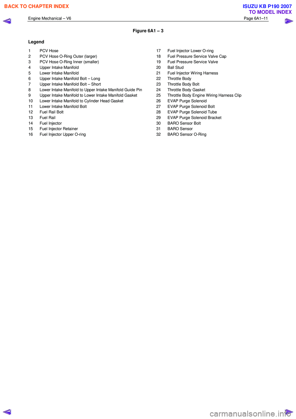
Figure 6A1 – 3
Legend
1 PCV Hose
2 PCV Hose O-Ring Outer (larger)
3 PCV Hose O-Ring Inner (smaller)
4 Upper Intake Manifold
5 Lower Intake Manifold
6 Upper Intake Manifold Bolt – Long
7 Upper Intake Manifold Bolt – Short
8 Lower Intake Manifold to Upper Intake Manifold Guide Pin
9 Upper Intake Manifold to Lower Intake Manifold Gasket
10 Lower Intake Manifold to Cylinder Head Gasket
11 Lower Intake Manifold Bolt
12 Fuel Rail Bolt
13 Fuel Rail
14 Fuel Injector
15 Fuel Injector Retainer
16 Fuel Injector Upper O-ring 17 Fuel Injector Lower O-ring
18 Fuel Pressure Service Valve Cap
19 Fuel Pressure Service Valve
20 Ball Stud
21 Fuel Injector Wiring Harness
22 Throttle Body
23 Throttle Body Bolt
24 Throttle Body Gasket
25 Throttle Body Engine Wiring Harness Clip
26 EVAP Purge Solenoid
27 EVAP Purge Solenoid Bolt
28 EVAP Purge Solenoid Tube
29 EVAP Purge Solenoid Bracket
30 BARO Sensor Bolt
31 BARO Sensor
32 BARO Sensor O-Ring
BACK TO CHAPTER INDEX
TO MODEL INDEX
ISUZU KB P190 2007
Page 2495 of 6020
Engine Mechanical – V6 Page 6A1–16
Oil Pump
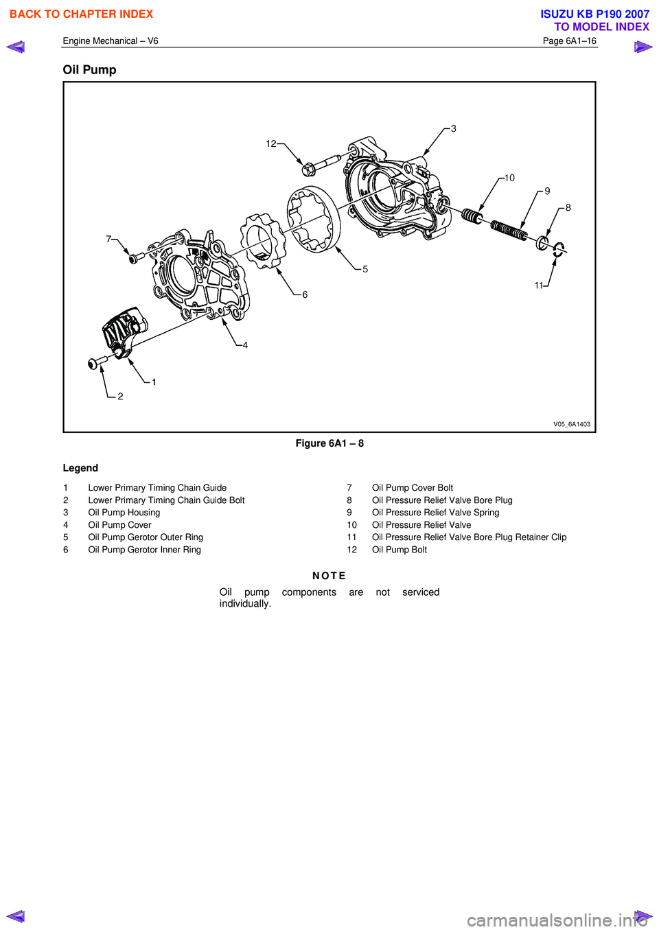
Figure 6A1 – 8
Legend
1 Lower Primary Timing Chain Guide
2 Lower Primary Timing Chain Guide Bolt
3 Oil Pump Housing
4 Oil Pump Cover
5 Oil Pump Gerotor Outer Ring
6 Oil Pump Gerotor Inner Ring 7 Oil Pump Cover Bolt
8 Oil Pressure Relief Valve Bore Plug
9 Oil Pressure Relief Valve Spring
10 Oil Pressure Relief Valve
11 Oil Pressure Relief Valve Bore Plug Retainer Clip
12 Oil Pump Bolt
NOTE
Oil pump components are not serviced
individually.
BACK TO CHAPTER INDEX
TO MODEL INDEX
ISUZU KB P190 2007
Page 2503 of 6020
Engine Mechanical – V6 Page 6A1–24
1.5 Engine Lubrication System
Lubrication Description
A structural diecast aluminium oil pan is fitted that incorporates an oil suction pipe, an oil deflector and an oil level sensor.
The oil suction pipe is bolted into the oil pan and seals to the bottom of the cylinder block with a gasket. The oil deflector
is bolted to the upper portion of the oil pan and ensures oil supply is maintained under all conditions. The oil level sensor
is mounted through the bottom of the oil pan.
A crankshaft driven gerotor oil pump is mounted to the front of the cylinder block. The pump, which incorporates an
internal pressure-relief valve, draws oil from the oil suction tube through the lower passage in the cylinder block. Oil is
then directed through an upper passage to the left-hand side of the cylinder block where the oil filter adapter is mounted.
The oil filter adapter incorporates a top-access, cartridge style oil filter. The filter is accessed through a screw-on cap tha t
incorporates an oil bypass valve. The oil filter adapter housing incorporates a drain back control valve and a threaded oil
pressure sender. Oil flows through a lower passage within the oil filter adapter and through the oil filter cartridge. Filtered
oil travels back through the upper passage of the adapter and into the engine block.
Oil is then directed up and across the front of the cylinder block, through several drilled passages. These front passages
feed oil to each cylinder head, the passage for the main bearings and piston oil jets, the right-hand and left-hand
secondary idler sprockets and to the primary timing chain tensioner.
Each cylinder head passage directs oil into oiling circuits for the stationary hydraulic lash adjusters (SHLAs) and the
camshaft bearing journals. An additional passage in the cylinder head also directs oil to the secondary timing chain
tensioner.
The oil passage that supplies oil to the main bearings also supplies oil to pressure actuated piston cooling oil jets. Each
oil jet is mounted between opposing cylinder bores and directs oil to the two bores to provide extra cooling and control
piston temperatures.
From the front passages, oil is directed to the front of the block where the right-hand and left-hand intermediate drive
shaft sprockets and the primary timing chain tensioner are mounted. Each camshaft timing chain tensioner relies on a
gasket to maintain an oil reserve after the engine is turned off. All camshaft timing chain tensioners incorporate a small
oil jet to supply an oil spray onto the camshaft timing chain components.
Oil returns to the oil pan, either through the camshaft timing chain area or through the drain back passages on the
outboard walls of the cylinder heads and cylinder block.
1.6 Service Notes
Cleanliness and Care
Throughout this Section, correct cleaning and protection of machined surfaces and friction areas is a part of the repair
procedure. This is considered standard workshop practice, even if not specifically stated.
W hen any internal engine part is serviced, care and cleanliness is extremely important.
W hen components are removed for service, they should be marked, organised or retained in a specific order for
reassembly.
At the time of installation, components should be installed in the same location and with the same mating surface as
when removed.
Any engine is a combination of many machined, honed, polished and lapped surfaces with tolerances that are measured
in thousandths of a millimetre. These surfaces should be covered or protected to avoid component damage.
A liberal coating of clean engine oil should be applied to friction areas during assembly, as the lubrication will protect and
lubricate friction surfaces during the initial engine start-up.
Replacing Engine Gaskets
Re-Using Gaskets and Applying Sealants
• do not reuse any gasket unless specified,
• gaskets that can be reused will be identified in the service procedure, and
• do not apply sealant to any gasket or sealing surface unless specified in the service information.
Separating Components
• Use a rubber mallet to separate components.
• Bump the part sideways to loosen the components.
• Bumping should be done at bends or reinforced areas to prevent distortion of parts.
Cleaning Gasket Surfaces
• W here required, remove all gasket and sealing material from the part using a plastic or wood scraper.
• Care must be used to avoid gouging or scraping the sealing surfaces.
BACK TO CHAPTER INDEX
TO MODEL INDEX
ISUZU KB P190 2007
Page 2504 of 6020
Engine Mechanical – V6 Page 6A1–25
• Do not use any other method or technique to remove sealant or gasket material from a part.
• Do not use abrasive pads, sand paper, or power tools to clean the gasket surfaces as these methods of cleaning
can cause damage to the component sealing surfaces. Abrasive pads also produce fine grit that the oil filter cannot
remove from the oil. This grit is abrasive and has been known to cause internal engine damage.
Assembling Components
• W hen assembling components, use only the sealant specified or equivalent in the service procedure.
• Sealing surfaces should be clean and free of debris or oil.
• Specific components such as crankshaft oil seals or valve stem oil seals may require lubrication during assembly.
• Components requiring lubrication will be identified in the service procedure.
• W hen applying sealant to a component, apply the amount specified in the service procedure.
• Do not allow the sealant to enter into any blind threaded holes as it may prevent the bolt from clamping correctly or
cause component damage when tightened.
• Only ever tighten bolts to the correct torque specification. Do not over-tighten.
Use of Room Temperature Vulcanising and Anaerobic Sealer
CAUTION
A number of sealant types are commonly
used in engines. Examples are; room
temperature vulcanising (RTV) sealer,
anaerobic gasket eliminator sealer, and
anaerobic thread sealant and pipe joint
compound. The correct type of sealant and
amount must be used in the specified location
to prevent oil leaks. Do not interchange the
different types of sealers.
Room Temperature Vulcanising Sealer
• Room temperature vulcanising (RTV) sealant hardens when exposed to air. This type of sealer is used where two
non-rigid parts (such as the intake manifold and the engine block) are assembled together.
• Do not use RTV sealant in areas where extreme temperatures are experienced. These areas include the exhaust
manifold, head gasket, or other surfaces where a gasket eliminator is specified.
• Follow all safety recommendations and directions that are on the container.
• To remove the sealant or the gasket material, refer to Replacing Engine Gaskets.
• Apply RTV to a clean surface. Use a bead size as specified in the service procedure. Run the bead to the inside of
any bolt holes. Do not allow the sealer to enter any blind threaded holes, as it may prevent the bolt from clamping
correctly or cause damage when the bolt is tightened.
• Assemble components while RTV is still wet (within 3 minutes). Do not wait for RTV to skin over.
• Tighten the bolts to the correct torque specification. Do not over-tighten.
Anaerobic Sealer
• Anaerobic gasket eliminator or thread sealant, hardens in the absence of air. This type sealer is used where two
rigid parts (such as castings) are assembled together, where fasteners are subjected to vibration, or where the
holes are not blind. W hen two rigid parts are disassembled and no sealer or gasket is readily noticeable, the parts
were probably assembled using a gasket eliminator.
• Follow all safety recommendations and directions that are on the container.
• To remove the sealant or the gasket material, refer to Replacing Engine Gaskets.
• Apply a continuous bead of gasket eliminator to one flange or on the bolt/stud thread. All surfaces must be clean
and dry.
• Spread the sealer evenly to achieve a uniform coating on the sealing surface.
• Do not allow the sealer to enter any blind threaded holes as it may prevent the bolt from clamping correctly or
cause damage when tightened.
BACK TO CHAPTER INDEX
TO MODEL INDEX
ISUZU KB P190 2007
Page 2505 of 6020
Engine Mechanical – V6 Page 6A1–26
CAUTION
Anaerobic sealed joints that are partially
tightened and allowed to cure more than five
minutes may result in incorrect shimming and
sealing of the joint.
• Tighten the bolts to the correct torque specification. Do not over-tighten.
• After correctly tightening the fasteners, remove the excess sealer from the outside of the joint.
Pipe Joint Compound
• Pipe joint compound is a pliable sealer that does not completely harden. This type of sealer is used where two non-
rigid parts (such as pressed steel and machined surfaces) are assembled together.
• Do not use pipe joint compound in areas where extreme temperatures are expected. These areas include the
exhaust manifold, head gasket, or other surfaces where gasket eliminator is specified.
• Follow all safety recommendations and directions that are on the container.
• To remove the sealant or the gasket material, refer to Replacing Engine Gaskets.
• Apply the pipe joint compound to a clean surface. Use a bead size or quantity as specified in the procedure. Run
the bead to the inside of any bolt holes. Do not allow the sealer to enter any blind threaded holes as it may prevent
the bolt from clamping correctly or cause component damage when the bolt is tightened.
• Apply a continuous bead of pipe joint compound to one sealing surface. Sealing surfaces to be resealed must be
clean and dry.
• Tighten the bolts to the correct torque specification. Do not over-tighten.
Separating Parts
CAUTION
Many internal engine components will
develop specific wear patterns on their
friction surfaces. When disassembling the
engine, internal components must be
separated, marked and organised in a way to
ensure reinstallation in their original location
and position.
Separate, mark, or organise the following components:
• Piston and the piston pin.
• Piston to the specific cylinder bore.
• Piston rings to the specific piston.
• Connecting rod to the crankshaft journal.
• Connecting rod to the bearing cap.
• Crankshaft main and connecting rod bearings.
• Camshaft and rocker arms.
• Rocker arms and stationary hydraulic lash adjusters to cylinder head location.
• Valve to the valve guide.
• Valve spring and shim to the cylinder head location.
• Engine block main bearing cap location and direction.
• Oil pump drive and driven gears.
Tools and Equipment
Special tools are listed and illustrated throughout this Section with a complete listing at the end, refer to 7 Special
Tools. These tools (or their equivalents) are specially designed to quickly and safely accomplish the operations for which
they are intended. The use of these special tools will also minimise possible damage to engine components. Some
precision measuring tools are required for inspection of certain critical components. A commercially available torque
wrench and torque angle wrench, Tool No. EN-7115 are required for the correct tightening of various fasteners.
To correctly service the engine assembly, the following items should be readily available:
• Approved eye protection and safety gloves.
BACK TO CHAPTER INDEX
TO MODEL INDEX
ISUZU KB P190 2007