2007 ISUZU KB P190 service
[x] Cancel search: servicePage 2970 of 6020
Engine Mechanical – V6 Page 6A1–193
Page 6A1–193
3.19 Camshaft Sprocket – MY06 Update
CAUTION
Setting the camshaft timing is required
whenever the camshaft drive system is
disturbed to ensure the relationship between
any chain and sprocket is not lost. Even when
only one sprocket is involved, multiple
crankshaft rotations will not produce
conditions where correct timing can be
confirmed.
If required, follow the Left-hand Secondary
Camshaft Chain Components reinstallation
procedure to reset the camshaft timing.
Remove
Right-hand Side
1 Remove the right-hand camshaft cover, refer to 3.12 Camshaft Cover.
2 Remove the camshaft position sensors, refer to Section 6C1-3 Engine Management – Service Operations.
3 Remove the camshaft position actuator solenoids, refer to Section 6C1-3 Engine Management – V6 – Service
Operations .
4 Remove the crankshaft bal ancer assembly, refer to 3.13 Crankshaft Balancer Assembly .
5 Install the crankshaft rotation socket Tool No. EN-46111 onto the crankshaft.
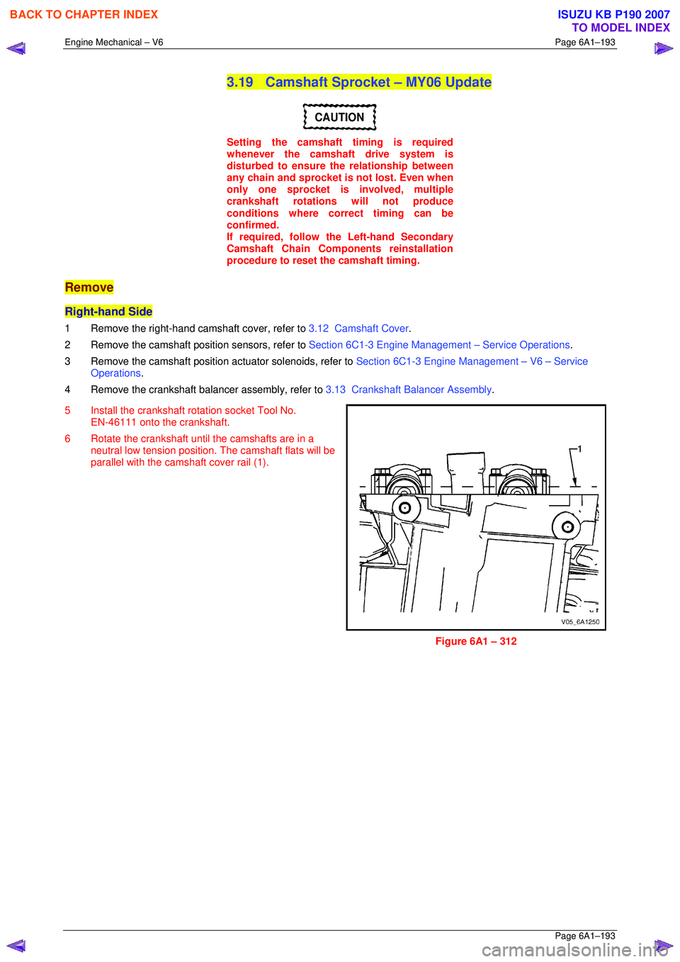
6 Rotate the crankshaft until the camshafts are in a neutral low tension position. The camshaft flats will be
parallel with the camshaft cover rail (1).
Figure 6A1 – 312
BACK TO CHAPTER INDEX
TO MODEL INDEX
ISUZU KB P190 2007
Page 2973 of 6020
Engine Mechanical – V6 Page 6A1–196
Page 6A1–196
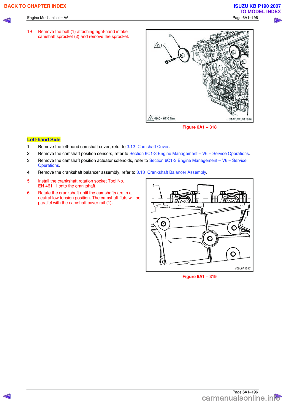
19 Remove the bolt (1) attaching right-hand intake
camshaft sprocket (2) and remove the sprocket.
Figure 6A1 – 318
Left-hand Side
1 Remove the left-hand cams haft cover, refer to 3.12 Camshaft Cover .
2 Remove the camshaft position sensors, refer to Section 6C1-3 Engine Management – V6 – Service Operations.
3 Remove the camshaft position actuator solenoids, refer to Section 6C1-3 Engine Management – V6 – Service
Operations .
4 Remove the crankshaft bal ancer assembly, refer to 3.13 Crankshaft Balancer Assembly .
5 Install the crankshaft rotation socket Tool No. EN-46111 onto the crankshaft.
6 Rotate the crankshaft until the camshafts are in a neutral low tension position. The camshaft flats will be
parallel with the camshaft cover rail (1).
Figure 6A1 – 319
BACK TO CHAPTER INDEX
TO MODEL INDEX
ISUZU KB P190 2007
Page 2995 of 6020
Engine Mechanical – V6 Page 6A1–218
Page 6A1–218
Left-hand Side (Bank 2) Cylinder Head
1 Remove the intake manifold assembly, refer to 3.10 Intake Manifold Assembly – Complete .
2 Remove the exhaust manifold, refer to 3.11 Exhaust Manifold Assembly.
3 Remove the power steering reservoi r and pump mounting brackets, refer to 3.8 Power Steering Pump Bracket.
NOTE
Do not disconnect the power steering pipes
and/or hoses.
4 Remove the oil filter adapter upper bolt. NOTE
Do not remove the oil filter adapter.
5 Remove the engine coolant temper ature (ECT) sensor, refer to Section 6C1-3 Engine Management – V6 – Service
Operations .
6 Remove engine harness ground terminal attach ing bolt from cylinder head, refer to Section 8A Electrical Body &
Chassis .
7 Remove the left-hand bank secondary timing chain, refer to 3.16 Timing Chains, Tensioners, Shoes and Guides.
8 Remove the camshaft position actuators, refer to 3.18 Camshaft Sprocket.
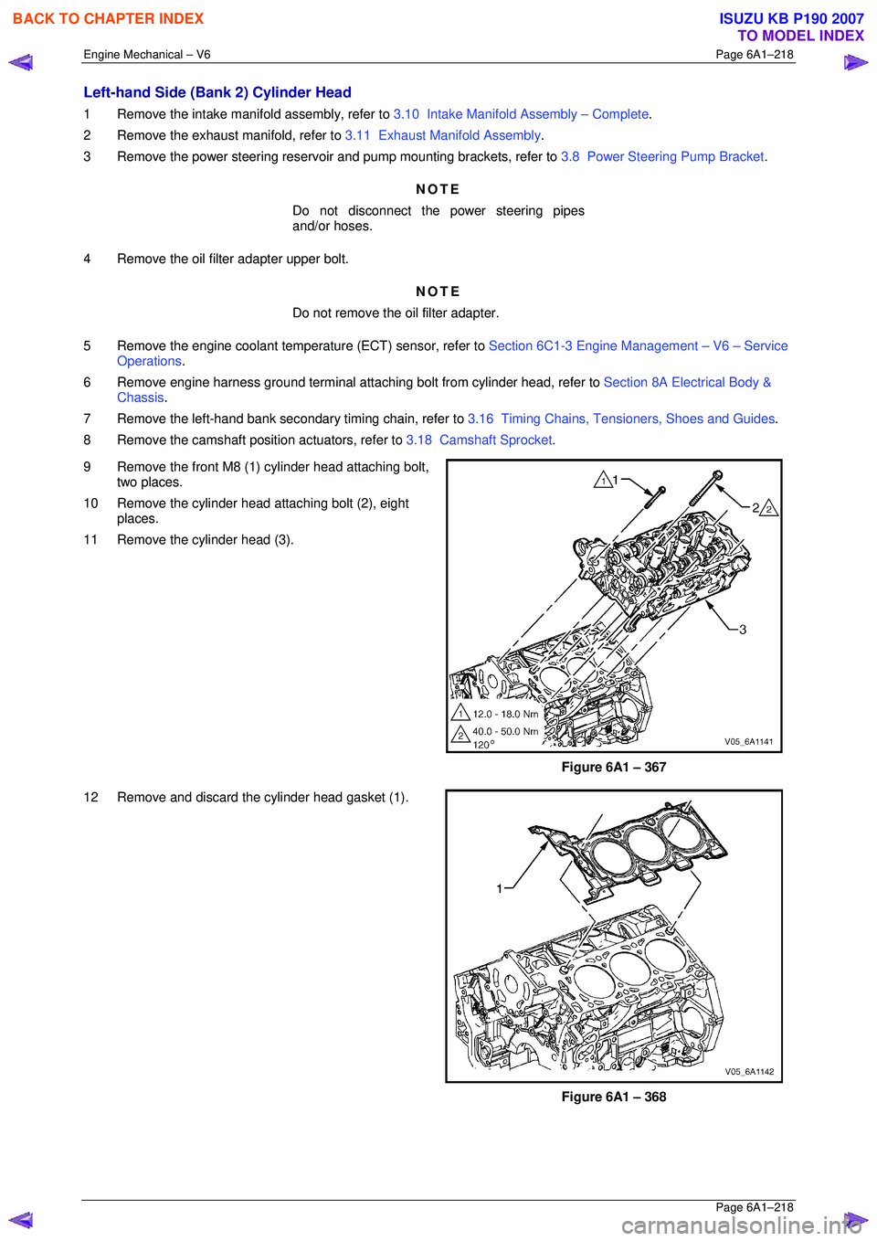
9 Remove the front M8 (1) cylinder head attaching bolt, two places.
10 Remove the cylinder head attaching bolt (2), eight places.
11 Remove the cylinder head (3).
Figure 6A1 – 367
12 Remove and discard the cylinder head gasket (1).
Figure 6A1 – 368
BACK TO CHAPTER INDEX
TO MODEL INDEX
ISUZU KB P190 2007
Page 3000 of 6020
Engine Mechanical – V6 Page 6A1–223
Page 6A1–223
Cylinder Head Measurement
NOTE
For all cylinder head and associated component
specifications, refer to 5 Specifications.
Camshaft Journal Clearance
1 Install the camshaft bearing cap in the cylinder head without the camshaft.
2 Install the camshaft cap bolts and tight en to the correct torque specification
Camshaft bearing cap attach ing bolt........ 8.0 – 12.0 Nm.
3 Measure the camshaft bearings using an inside micrometer.
4 Subtract the camshaft journal diam eter from the camshaft bearing diameter. This will provide the running
clearance. If the running clearance exceeds specifications and the camshaft journals are within specification,
replace the cylinder head.
Camshaft Journal Alignment
1 Ensure the camshafts are serviceable, refer to 3.19 Camshaft for measuring procedures.
2 Inspect the cylinder head camshaft bearing surfaces for any imperfections or scratches that could inhibit correct
camshaft clearances. Repair minor imperfections or scratches.
3 Install the camshafts in the cylinder head.
4 Install the camshaft bearing caps.
5 Install the camshaft cap bolts and tighten to the correct torque specification.
Camshaft bearing cap attach ing bolt........ 8.0 – 12.0 Nm.
6 Ensure the camshafts spin freely in the cylinder head. If the camshaft does not run freely, replace the cylinder
head.
Deck Flatness Inspection
1 Ensure the cylinder head decks are clean and free of gasket material.
2 Inspect the surface for any imperfections or scratches
that could inhibit correct cylinder head gasket sealing.
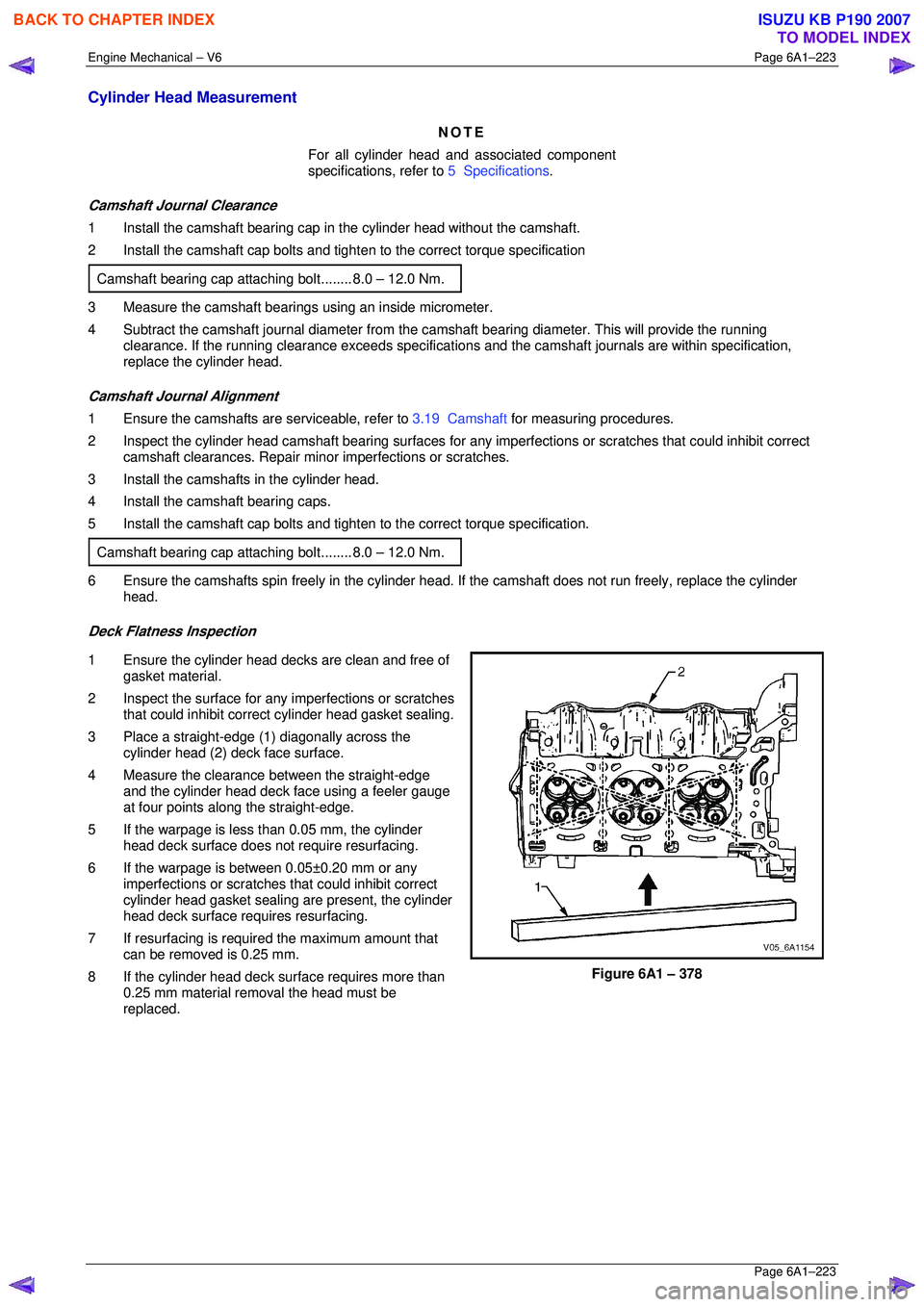
3 Place a straight-edge (1) diagonally across the cylinder head (2) deck face surface.
4 Measure the clearance between the straight-edge
and the cylinder head deck face using a feeler gauge
at four points along the straight-edge.
5 If the warpage is less t han 0.05 mm, the cylinder
head deck surface does not require resurfacing.
6 If the warpage is between 0.05±0.20 mm or any imperfections or scratches that could inhibit correct
cylinder head gasket sealing are present, the cylinder
head deck surface requires resurfacing.
7 If resurfacing is requir ed the maximum amount that
can be removed is 0.25 mm.
8 If the cylinder head deck surface requires more than 0.25 mm material removal the head must be
replaced.
Figure 6A1 – 378
BACK TO CHAPTER INDEX
TO MODEL INDEX
ISUZU KB P190 2007
Page 3001 of 6020
Engine Mechanical – V6 Page 6A1–224
Page 6A1–224
Valve Guide Measurement
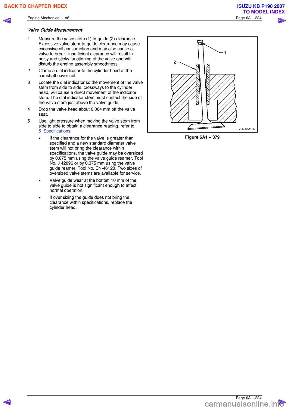
1 Measure the valve stem (1) to-guide (2) clearance.
Excessive valve stem-to-guide clearance may cause
excessive oil consumption and may also cause a
valve to break. Insufficient clearance will result in
noisy and sticky functioning of the valve and will
disturb the engine assembly smoothness.
2 Clamp a dial indicator to the cylinder head at the camshaft cover rail.
3 Locate the dial indicator so the movement of the valve
stem from side to side, crossways to the cylinder
head, will cause a direct mo vement of the indicator
stem. The dial indicator stem must contact the side of
the valve stem just above the valve guide.
4 Drop the valve head about 0.064 mm off the valve seat.
5 Use light pressure when moving the valve stem from side to side to obtain a clearance reading, refer to
5 Specifications .
• If the clearance for the valve is greater than
specified and a new st andard diameter valve
stem will not bring the clearance within
specifications, the valv e guide may be oversized
by 0.075 mm using the valve guide reamer, Tool
No. J 42096 or by 0.375 mm using the valve
guide reamer, Tool No. EN-46120. Two sizes of
oversized valve stems are available for service.
• Valve guide wear at the bottom 10 mm of the
valve guide is not significant enough to affect
normal operation.
• If over sizing the guide does not bring the
clearance within specif ications, replace the
cylinder head.
Figure 6A1 – 379
BACK TO CHAPTER INDEX
TO MODEL INDEX
ISUZU KB P190 2007
Page 3003 of 6020
Engine Mechanical – V6 Page 6A1–226
Page 6A1–226
Valve Visual Inspection Procedure
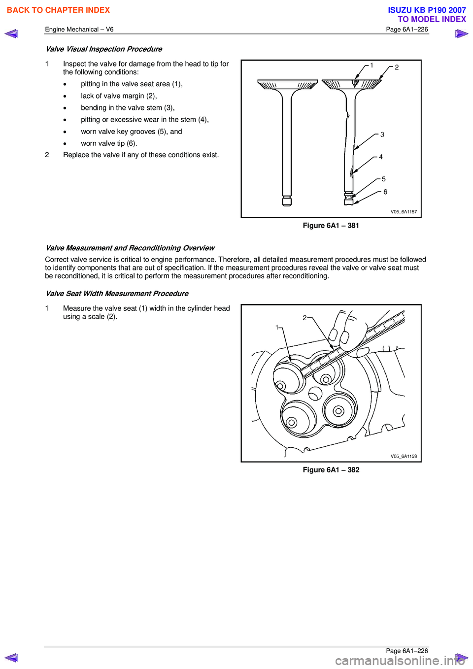
1 Inspect the valve for damage from the head to tip for
the following conditions:
• pitting in the valve seat area (1),
• lack of valve margin (2),
• bending in the valve stem (3),
• pitting or excessive wear in the stem (4),
• worn valve key grooves (5), and
• worn valve tip (6).
2 Replace the valve if any of these conditions exist.
Figure 6A1 – 381
Valve Measurement and Reconditioning Overview
Correct valve service is critical to engine performance. Therefore, all detailed measurement procedures must be followed
to identify components that are out of specification. If the measurement procedures reveal t he valve or valve seat must
be reconditioned, it is critical to perform t he measurement procedures after reconditioning.
Valve Seat Width Measurement Procedure
1 Measure the valve seat (1) width in the cylinder head
using a scale (2).
Figure 6A1 – 382
BACK TO CHAPTER INDEX
TO MODEL INDEX
ISUZU KB P190 2007
Page 3016 of 6020
Engine Mechanical – V6 Page 6A1–239
Page 6A1–239
4 Major Service Operations
ATTENTION
The V6 engine is a combination of numerous components, containing machined, honed, polished and lapped
surfaces manufactured on the latest, high technology production equipment. Many of the components
contain tolerances measured in thousa ndths of a millimetre. Consequently, when any e ngine component is to
be serviced, care and cleanliness are extremely important.
Prior to re-assembly of the V6 engi ne, all components must be cleaned and inspected in accordance with the
relevant procedures throughout this section, and replaced or repaired where required.
In addition to cleaning and inspecting components, a liberal coating of engine oil should be applied to friction
surfaces during assembly to protect and lubr icate the surfaces on initial operation.
When performing any service operation contained in this Section, it should be understood that correct
cleaning and protection of machined surfaces and fricti on areas is part of the repair procedure. This is
considered standard workshop practice, even if not specifically stated. Torque values must be used as
specified during reassembly to ensure correct retention of all components.
Through out this section, fastener torque wrench sp ecifications may be accompanied with the following
identification marks:
■ Fasteners must be replaced after loosening.
Fasteners either have micro encapsulated sealant a pplied or incorporate a mechanical thread lock and
should only be re-used once. If in doubt, replacement is recommended.
If one of these identification marks is present alongs ide a fastener torque wrench specification, the
recommendation regarding that fastener must be adhered to.
4.1 Engine Removal
CAUTION
• Allow the engine to cool to at least 50 ° C,
before attempting fastener removal.
• As aluminium has a greater rate of thermal
expansion than that of cast iron,
aluminium bolt hole threads will change
dimension to a larger extent than cast iron
bolt threads.
• If a bolt or other threaded component is
removed before the engine is allowed to
cool to at least 50 ° C, threads could be
pulled from the cylinder block or cylinder
head.
• Do not use impact tools to remove bolts
during engine disassembly. While this may
be common practice with cast iron engine
components, use of th ese tools is likely to
pull the aluminium threads in the cylinder
block or head of this engine.
BACK TO CHAPTER INDEX
TO MODEL INDEX
ISUZU KB P190 2007
Page 3029 of 6020
Engine Mechanical – V6 Page 6A1–252
Page 6A1–252
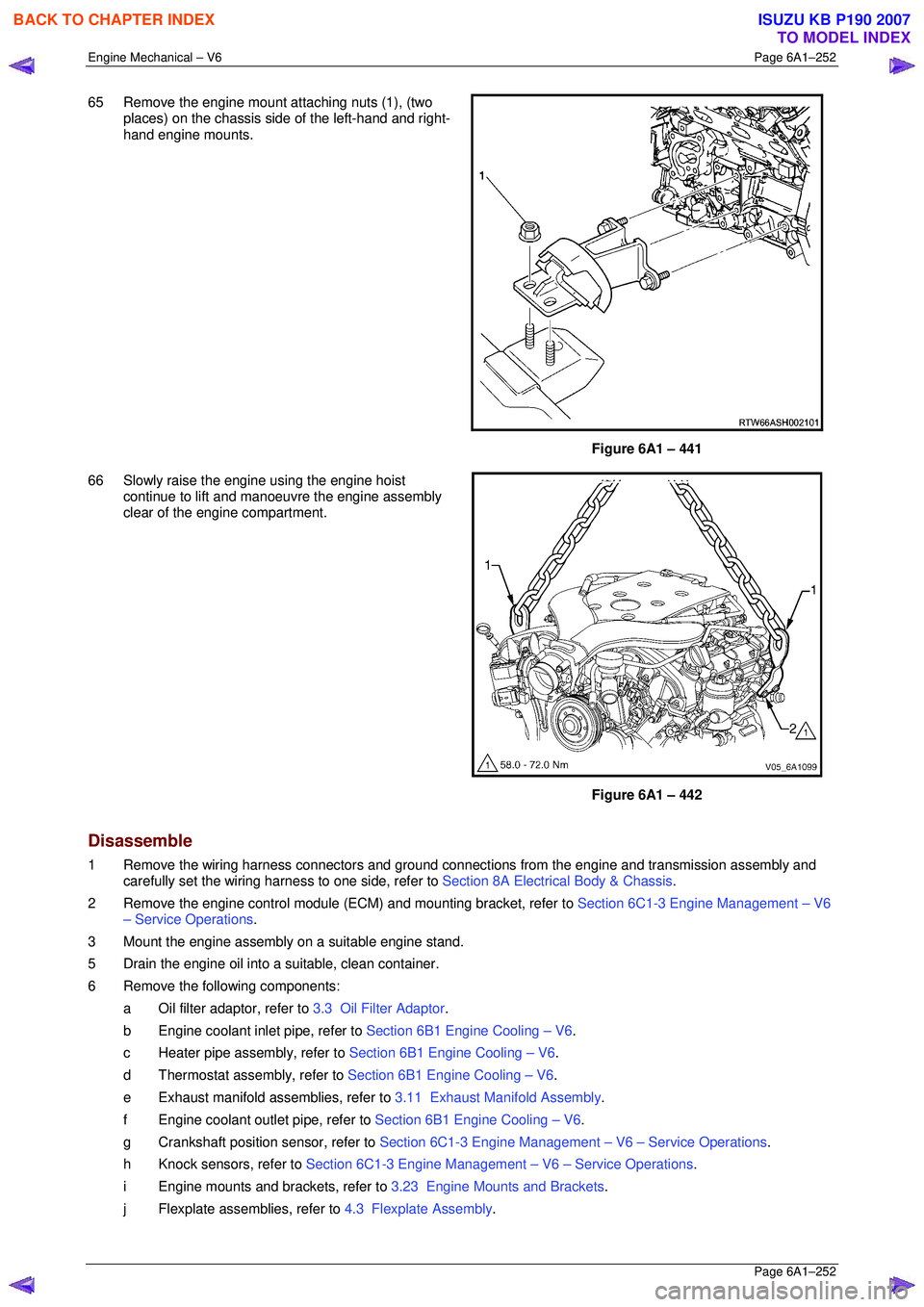
65 Remove the engine mount attaching nuts (1), (two
places) on the chassis si de of the left-hand and right-
hand engine mounts.
Figure 6A1 – 441
66 Slowly raise the engine using the engine hoist continue to lift and manoeuvre the engine assembly
clear of the engine compartment.
Figure 6A1 – 442
Disassemble
1 Remove the wiring harness connectors and ground connec tions from the engine and transmission assembly and
carefully set the wiring harness to one side, refer to Section 8A Electrical Body & Chassis.
2 Remove the engine control module (ECM) and mounting bracket, refer to Section 6C1-3 Engine Management – V6
– Service Operations .
3 Mount the engine assembly on a suitable engine stand.
5 Drain the engine oil into a suitable, clean container.
6 Remove the following components: a Oil filter adaptor, refer to 3.3 Oil Filter Adaptor.
b Engine coolant inlet pipe, refer to Section 6B1 Engine Cooling – V6.
c Heater pipe assembly, refer to Section 6B1 Engine Cooling – V6.
d Thermostat assembly, refer to Section 6B1 Engine Cooling – V6.
e Exhaust manifold a ssemblies, refer to 3.11 Exhaust Manifold Assembly .
f Engine coolant outlet pipe, refer to Section 6B1 Engine Cooling – V6.
g Crankshaft position sensor, refer to Section 6C1-3 Engine Management – V6 – Service Operations.
h Knock sensors, refer to Section 6C1-3 Engine Management – V6 – Service Operations.
i Engine mounts and brackets, refer to 3.23 Engine Mounts and Brackets.
j Flexplate assemblies, refer to 4.3 Flexplate Assembly.
BACK TO CHAPTER INDEX
TO MODEL INDEX
ISUZU KB P190 2007