2007 ISUZU KB P190 service
[x] Cancel search: servicePage 3154 of 6020
Engine Cooling – V6 Engine Page 6B1–19
a Place a few drops of distilled water (between 21 and 29° C) onto the measuring window, then close the
plastic cover.
b Point the tester toward any light source, look into the eyepiece and check that the indicated reading is zero. If not, then re-calibrate the tester as detailed at the end of this Test Method, Calibrating the Tester.
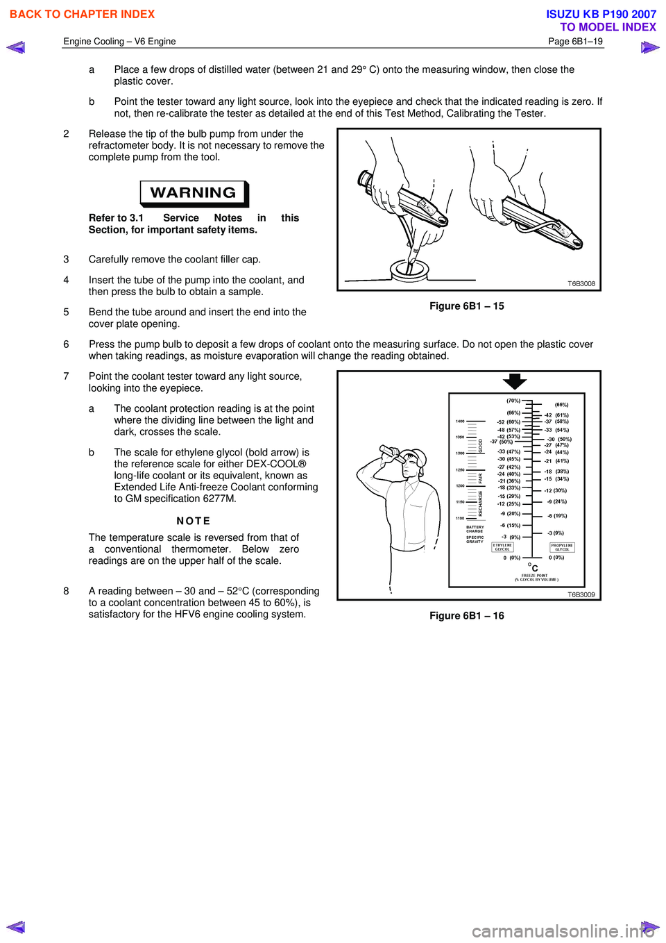
2 Release the tip of the bulb pump from under the refractometer body. It is not necessary to remove the
complete pump from the tool.
Refer to 3.1 Service Notes in this
Section, for important safety items.
3 Carefully remove the coolant filler cap.
4 Insert the tube of the pump into the coolant, and then press the bulb to obtain a sample.
5 Bend the tube around and insert the end into the cover plate opening.
Figure 6B1 – 15
6 Press the pump bulb to deposit a few drops of coolant onto the measuring surface. Do not open the plastic cover when taking readings, as moisture evaporation will change the reading obtained.
7 Point the coolant tester toward any light source, looking into the eyepiece.
a The coolant protection reading is at the point where the dividing line between the light and
dark, crosses the scale.
b The scale for ethylene glycol (bold arrow) is the reference scale for either DEX-COOL®
long-life coolant or its equivalent, known as
Extended Life Anti-freeze Coolant conforming
to GM specification 6277M.
NOTE
The temperature scale is reversed from that of
a conventional thermometer. Below zero
readings are on the upper half of the scale.
8 A reading between – 30 and – 52 °C (corresponding
to a coolant concentration between 45 to 60%), is
satisfactory for the HFV6 engine cooling system.
Figure 6B1 – 16
BACK TO CHAPTER INDEX
TO MODEL INDEX
ISUZU KB P190 2007
Page 3157 of 6020
Engine Cooling – V6 Engine Page 6B1–22
3.3 Draining and Filling Cooling System
Draining
Refer to 3.1 Service Notes in this Section, for
important safety items.
1 Allow engine to cool to ambient temperature (less than 50 ° C), and then remove the coolant filler cap (located near
the brake booster assembly).
Disconnection of the battery affects certain
vehicle electronic systems. Refer to 1.1
WARNING, CAUTION and NOTES, before
removing the ground lead.
2 Disconnect the battery ground lead. Refer to 6D1– 3 Battery – V6.
3 Drain the coolant from the system via the radiator drain tap on the lower RHS of the radiator below the lower hose outlet. Attach a suitable piece of rubber tubing to the tap outlet to help direct the flow of the coolant into a suitable
container (capacity at least 12 litres).
Filling
During any service operation that requires the cooling system to be partly or completely drained, the following
instructions must be followed when refilling the cooling system, to ensure that all air is bleed from system.
• Refer to 3.1 Service Notes in this Section,
for important safety items.
• Before opening the radiator bleed screw,
the cooling system must first be
completely depressurised with the engine
coolant filler cap removed.
Do not mix different types of anti-freeze or
corrosion inhibitors, as they may be
incompatible. Always check which coolant is
to be added to the particular vehicle being
serviced. If a different type has been used in
the cooling system (or is added accidentally),
flush the system with clean water. Refer to 3.4
Cleaning Cooling System in this Section.
NOTE
Ensure that the radiator drain tap located at the
bottom of right-hand side radiator tank is closed
before proceeding.
BACK TO CHAPTER INDEX
TO MODEL INDEX
ISUZU KB P190 2007
Page 3160 of 6020
Engine Cooling – V6 Engine Page 6B1–25
3.4 Cleaning Cooling System
NOTE
• Before carrying out reverse flushing
procedures, it is recommended that a
cleaning solution be used to loosen scale and
corrosion. Only use a Holden approved
radiator cleaner following the instructions on
the container label.
• This operation should only be carried out
when the engine and radiator are at ambient
temperature.
• When using specialised cooling system
flushing equipment, connect the equipment as
recommended by the manufacturer.
Cooling System Reverse Flush
Radiator
Refer to ‘
‘‘
‘
Environmental Issues ’
’’
’
in 3.1
Service Notes, before draining the coolant.
1 Drain the cooling system. Refer to 3.3 Draining and Filling Cooling System in this Section.
Always wear eye protection when working
with spring-type hose clamps. Failure to do
so may result in eye injury.
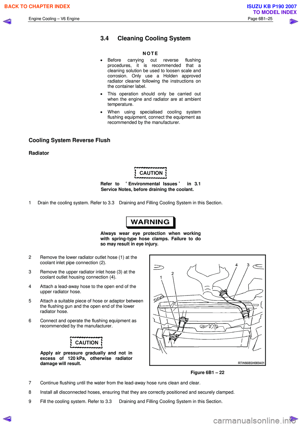
2 Remove the lower radiator outlet hose (1) at the coolant inlet pipe connection (2).
3 Remove the upper radiator inlet hose (3) at the coolant outlet housing connection (4).
4 Attach a lead-away hose to the open end of the upper radiator hose.
5 Attach a suitable piece of hose or adaptor between the flushing gun and the open end of the lower
radiator hose.
6 Connect and operate the flushing equipment as recommended by the manufacturer.
Apply air pressure gradually and not in
excess of 120 kPa, otherwise radiator
damage will result.
Figure 6B1 – 22
7 Continue flushing until the water from the lead-away hose runs clean and clear.
8 Install all disconnected hoses, ensuring that they are correctly positioned and securely clamped.
9 Fill the cooling system. Refer to 3.3 Draining and Filling Cooling System in this Section.
BACK TO CHAPTER INDEX
TO MODEL INDEX
ISUZU KB P190 2007
Page 3161 of 6020
Engine Cooling – V6 Engine Page 6B1–26
10 Pressure test the cooling system. Refer to 3.7 Pressure Testing in this Section.
Engine
Refer to ‘
‘‘
‘
Environmental Issues ’
’’
’
in 3.1
Service Notes, before draining the coolant.
1 Drain the cooling system. Refer to 3.3 Draining and Filling Cooling System in this Section.
Always wear eye protection when working
with spring-type hose clamps. Failure to do
so may result in eye injury.
2 Remove the upper and lower radiator hoses from the coolant outlet housing and coolant inlet pipe connections. Refer to Figure 6B1 – 22.
3 Remove the thermostat housing from the rear of the engine block. Refer to 6A1 Engine Mechanical – V6..
4 Remove the thermostat from the thermostat housing and reinstall the housing to the rear of the intake manifold. Refer to 3.8 Thermostat in this Section.
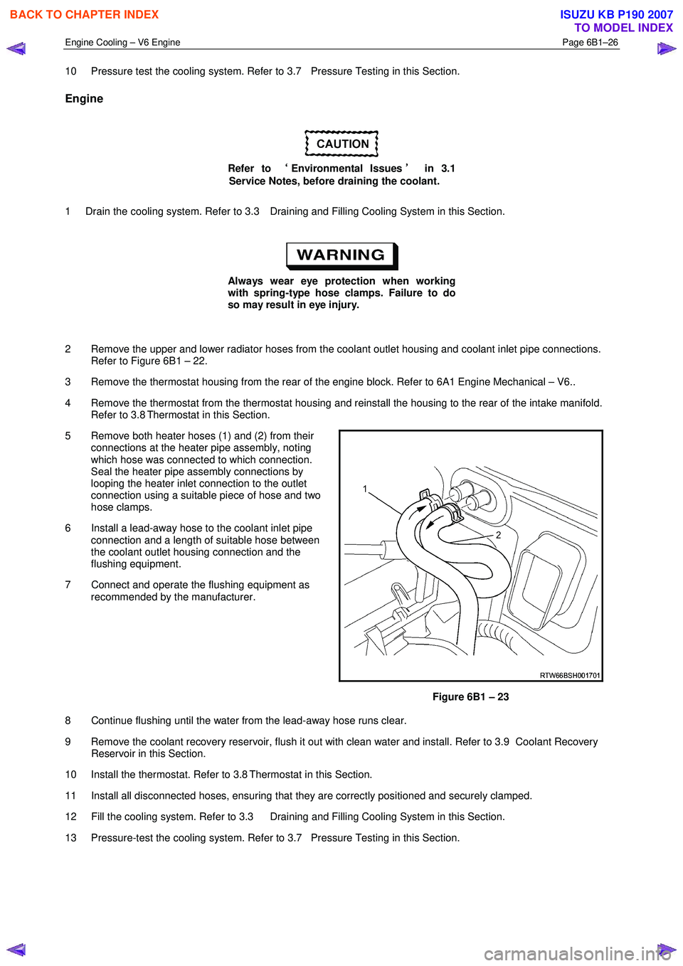
5 Remove both heater hoses (1) and (2) from their connections at the heater pipe assembly, noting
which hose was connected to which connection.
Seal the heater pipe assembly connections by
looping the heater inlet connection to the outlet
connection using a suitable piece of hose and two
hose clamps.
6 Install a lead-away hose to the coolant inlet pipe connection and a length of suitable hose between
the coolant outlet housing connection and the
flushing equipment.
7 Connect and operate the flushing equipment as recommended by the manufacturer.
Figure 6B1 – 23
8 Continue flushing until the water from the lead-away hose runs clear.
9 Remove the coolant recovery reservoir, flush it out with clean water and install. Refer to 3.9 Coolant Recovery Reservoir in this Section.
10 Install the thermostat. Refer to 3.8 Thermostat in this Section.
11 Install all disconnected hoses, ensuring that they are correctly positioned and securely clamped.
12 Fill the cooling system. Refer to 3.3 Draining and Filling Cooling System in this Section.
13 Pressure-test the cooling system. Refer to 3.7 Pressure Testing in this Section.
BACK TO CHAPTER INDEX
TO MODEL INDEX
ISUZU KB P190 2007
Page 3162 of 6020
Engine Cooling – V6 Engine Page 6B1–27
Heater Hoses and Core
Refer to ‘
‘‘
‘
Environmental Issues ’
’’
’
in 3.1
Service Notes, before draining the coolant.
1 Drain the cooling system. Refer to 3.3 Draining and Filling Cooling System in this Section.
Always wear eye protection when working
with spring-type hose clamps. Failure to do
so may result in eye injury.
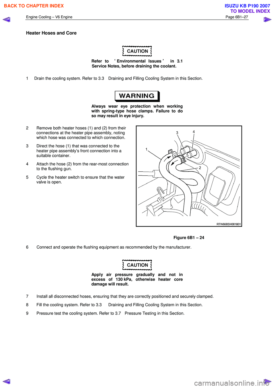
2 Remove both heater hoses (1) and (2) from their connections at the heater pipe assembly, noting
which hose was connected to which connection.
3 Direct the hose (1) that was connected to the heater pipe assembly’s front connection into a
suitable container.
4 Attach the hose (2) from the rear-most connection to the flushing gun.
5 Cycle the heater switch to ensure that the water valve is open.
Figure 6B1 – 24
6 Connect and operate the flushing equipment as recommended by the manufacturer.
Apply air pressure gradually and not in
excess of 130 kPa, otherwise heater core
damage will result.
7 Install all disconnected hoses, ensuring that they are correctly positioned and securely clamped.
8 Fill the cooling system. Refer to 3.3 Draining and Filling Cooling System in this Section.
9 Pressure test the cooling system. Refer to 3.7 Pressure Testing in this Section.
BACK TO CHAPTER INDEX
TO MODEL INDEX
ISUZU KB P190 2007
Page 3166 of 6020
Engine Cooling – V6 Engine Page 6B1–31
3.7 Pressure Testing
Coolant Filler Cap Pressure Testing
Refer to 3.1 Service Notes in this Section, for
important safety items.
1 Allow engine to cool to ambient temperature (less than 50 ° C), then remove coolant filler cap.
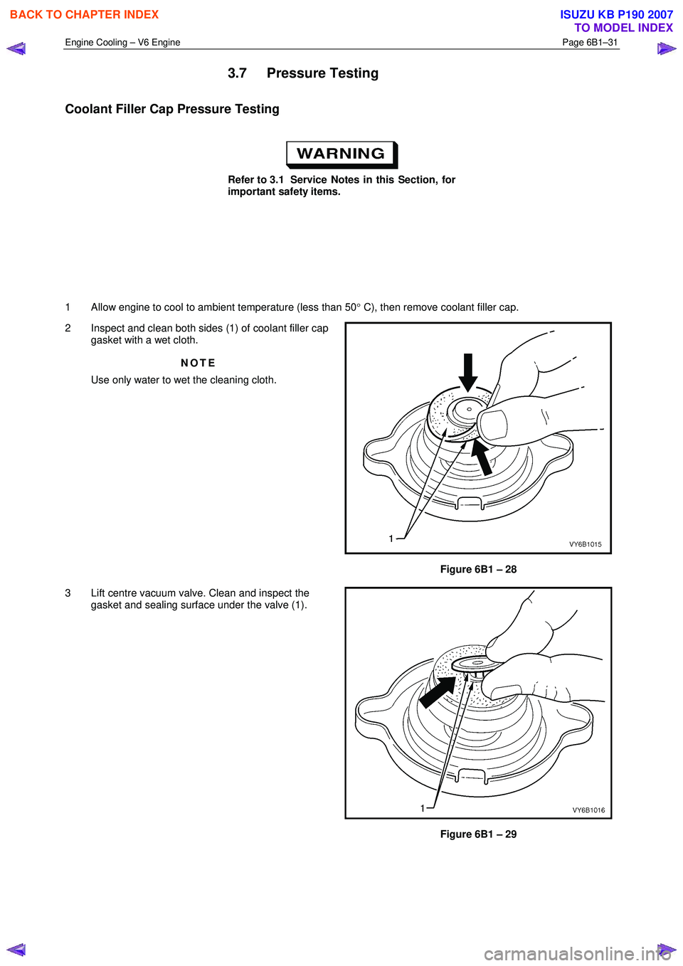
2 Inspect and clean both sides (1) of coolant filler cap gasket with a wet cloth.
NOTE
Use only water to wet the cleaning cloth.
Figure 6B1 – 28
3 Lift centre vacuum valve. Clean and inspect the gasket and sealing surface under the valve (1).
Figure 6B1 – 29
BACK TO CHAPTER INDEX
TO MODEL INDEX
ISUZU KB P190 2007
Page 3167 of 6020
Engine Cooling – V6 Engine Page 6B1–32
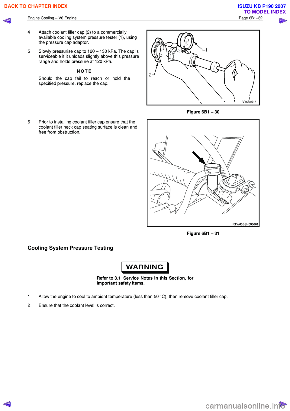
4 Attach coolant filler cap (2) to a commercially
available cooling system pressure tester (1), using
the pressure cap adaptor.
5 Slowly pressurise cap to 120 – 130 kPa. The cap is serviceable if it unloads slightly above this pressure
range and holds pressure at 120 kPa.
NOTE
Should the cap fail to reach or hold the
specified pressure, replace the cap.
Figure 6B1 – 30
6 Prior to installing coolant filler cap ensure that the coolant filler neck cap seating surface is clean and
free from obstruction.
Figure 6B1 – 31
Cooling System Pressure Testing
Refer to 3.1 Service Notes in this Section, for
important safety items.
1 Allow the engine to cool to ambient temperature (less than 50 ° C), then remove coolant filler cap.
2 Ensure that the coolant level is correct.
BACK TO CHAPTER INDEX
TO MODEL INDEX
ISUZU KB P190 2007
Page 3169 of 6020
Engine Cooling – V6 Engine Page 6B1–34
3.8 Thermostat
Remove
Do not remove coolant filler cap while the
engine coolant temperature is above 50 °
°°
°
C, as
personal injury may result.
1 Allow engine to cool to ambient temperature (less than 50 ° C), then remove the coolant filler cap (located at the
front left-hand side of the engine).
Disconnection of the battery affects certain
vehicle electronic systems. Refer to 00
Warnings, Cautions and Notes, before
removing the ground lead.
2 Disconnect the battery ground lead. Refer to 6D1-3 Battery – V6.
Refer to ‘
‘‘
‘
Environmental Issues ’
’’
’
in 3.1
Service Notes, before draining the coolant.
3 Drain the coolant from the system. Refer to 3.3 Draining and Filling Cooling System in this Section.
4 Remove the complete intake manifold assembly. Refer to 6A1 Engine Mechanical – V6.
5 Plug each of the exposed intake ports with lint free cloth to prevent the entry of foreign matter.
6 Remove the coolant inlet pipe. Refer to 3.12 Coolant Inlet Pipe in this Section.
Always wear protective safety glasses when
working with spring type hose clamps.
Failure to do so could result in eye injury.
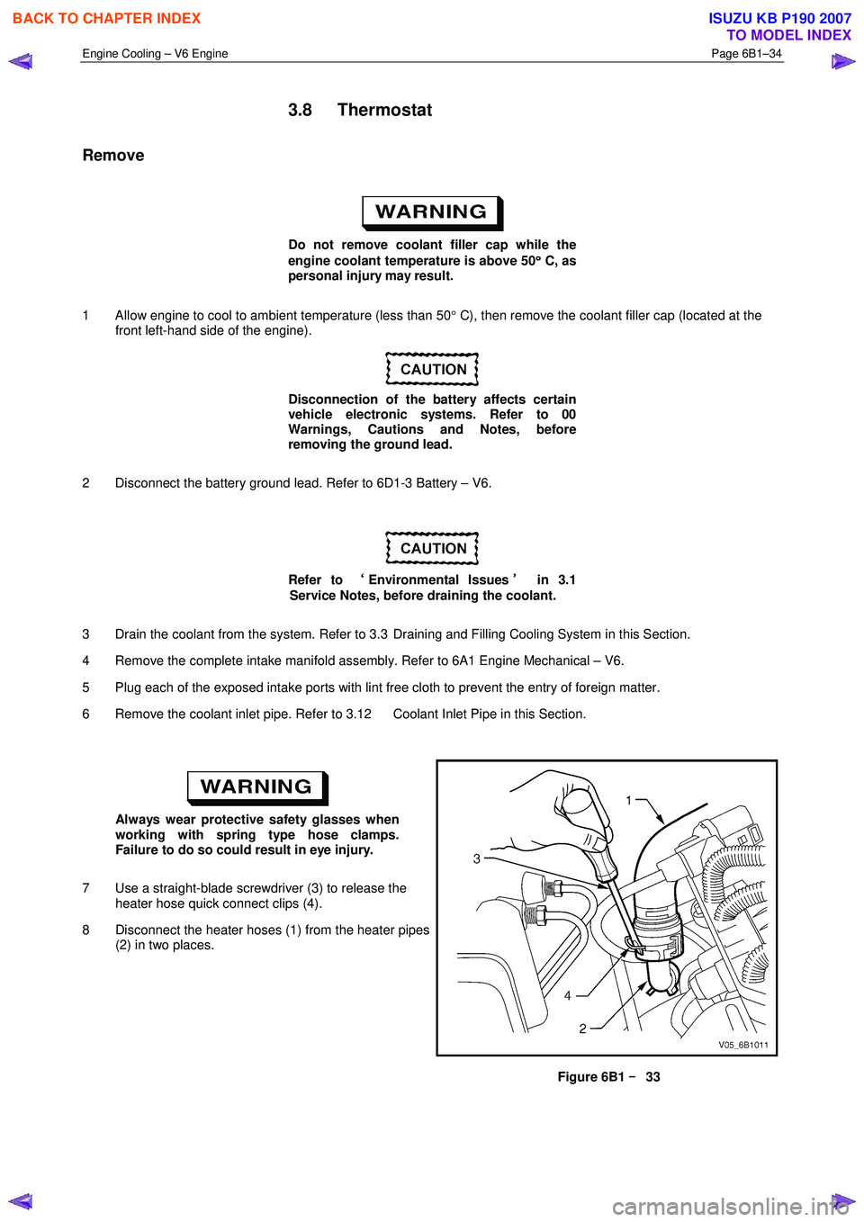
7 Use a straight-blade screwdriver (3) to release the heater hose quick connect clips (4).
8 Disconnect the heater hoses (1) from the heater pipes (2) in two places.
Figure 6B1 –
––
–
33
BACK TO CHAPTER INDEX
TO MODEL INDEX
ISUZU KB P190 2007