Page 3213 of 6020
Fuel System – V6 Page 6C – 11
Figure 6C – 6
5 Replace any faulty components and repeat step 2 to step 5 inclusive.
6 Replace all engine components removed to perform the fuel leak test, refer to 6C1-3 Engine Management – V6 – Service Operations.
3.4 Fuel System Depressurisation
To reduce the risk of fire or personal injury,
depressurise the fuel system before servicing
any fuel system components.
1 Turn the ignition switch off.
2 Remove the fuel pump fuse and fuel pump relay, refer to 8A Electrical Body and Chassis.
3 Loosen the fuel filler cap to relieve the fuel tank vapour pressure.
4 W ith the throttle closed, crank the engine.
NOTE
The engine may start and operate until the fuel
remaining in the fuel delivery system depletes.
5 W hen the engine stops, crank the engine for another 10 seconds to ensure the fuel feed line pressure has been fully relieved.
6 Clean the area around the fuel pressure test point.
BACK TO CHAPTER INDEX
TO MODEL INDEX
ISUZU KB P190 2007
Page 3215 of 6020
Fuel System – V6 Page 6C – 13
4 Service Operations
4.1 Fuel Lines And Quick Connect Fittings
Description
The fuel line connector fittings contain the following
components:
1 O-rings
2 Fuel line port
3 Connector
4 Plastic fuel line tube
Figure 6C – 8
Leak Test and Inspection
1. Turn the ignition key to the ON position and ensure the fuel pump runs for a short time by listening for the pump start up sound. The fuel pressure will increase when the fuel pump is actuated.
2 Perform a preliminary check of the system by inspecting the system for any leaks around the connections and fittings.
3 Perform steps 1 and 2 several times.
4 If the preliminary check of the system produces no leaks, start the engine and check the system again for any sign of leaks around the connections and lines.
Ensure all service precautions have been
observed prior to removing any connector
fittings.
BACK TO CHAPTER INDEX
TO MODEL INDEX
ISUZU KB P190 2007
Page 3221 of 6020
Fuel System – V6 Page 6C – 19
Remove
• A depressurised fuel system contains fuel
in the fuel filter and fuel lines that can be
spilled during service operations.
• Fuel vapour remains in the fuel tank even
when completely empty. Seal all openings
in the fuel tank using suitable material or a
plastic plug. Ensure no naked flames or
other ignition sources are nearby. Ensure
all cellular phones (and transmission
devices that may cause any metal objects
to become unintentional receiving
antennas) are switched off.
• Place a dry chemical (Class B) fire
extinguisher nearby before performing any
on-vehicle service procedures. Failure to
follow these precautions may result in
personal injury.
1 Remove the fuel pump relay, refer to 8A Electrical Body and Chassis.
2 Depressurise the fuel system, refer to 3.4 Fuel System Depressurisation.
Never drain or store fuel into an open
container, due to the possibility of fire or
explosion.
3 Siphon the fuel tank, using commercially-available equipment.
Before proceeding, clean all traces of dirt and
other foreign material from the top of the fuel
tank, near the modular fuel pump and sender
assembly.
7 Place a drain tray under the fuel filter area.
Fuel can spill from the disconnected filter.
BACK TO CHAPTER INDEX
TO MODEL INDEX
ISUZU KB P190 2007
Page 3225 of 6020
Fuel System – V6 Page 6C – 23
4.5 Modular Fuel Pump and Sender
Assembly
NOTE
If the modular fuel pump and sender assembly
develops a fault it must be replaced as a
complete unit. The only serviced parts are the
retainer locking ring and the O-ring seal.
Remove
• A depressurised fuel system contains fuel
in the fuel filter and fuel lines that can be
spilled during service operations.
• Fuel vapour remains in the fuel tank even
when completely empty. Seal all openings
in the fuel tank using suitable material or a
plastic plug. Ensure no naked flames or
other ignition sources are nearby. Ensure
all cellular phones (and transmission
devices that may cause any metal objects
to become unintentional receiving
antennas) are switched off.
• Place a dry chemical (Class B) fire
extinguisher nearby before performing any
on-vehicle service procedures. Failure to
follow these precautions may result in
personal injury.
• Wear safety glasses when using
compressed air. Do not blow compressed
air directly onto any body part.
1 Remove the fuel pump relay, refer to 8A Engine Body and Chassis.
2 Remove the fuel tank assembly from the vehicle, refer to 4.4 Fuel Tank.
Before proceeding, clean all traces of dirt and
other foreign material from the top of the fuel
tank, near the modular fuel pump and sender
assembly.
3 Use compressed air to ensure all dirt and foreign materials are removed from all fuel connections before disconnecting the parts.
Fuel can spill from the disconnected modular
fuel pump and sender assembly.
BACK TO CHAPTER INDEX
TO MODEL INDEX
ISUZU KB P190 2007
Page 3227 of 6020
Fuel System – V6 Page 6C – 25
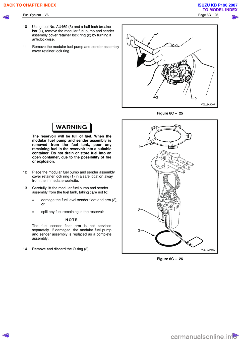
10 Using tool No. AU469 (3) and a half-inch breaker
bar (1), remove the modular fuel pump and sender
assembly cover retainer lock ring (2) by turning it
anticlockwise.
11 Remove the modular fuel pump and sender assembly cover retainer lock ring.
Figure 6C – 25
The reservoir will be full of fuel. When the
modular fuel pump and sender assembly is
removed from the fuel tank, pour any
remaining fuel in the reservoir into a suitable
container. Do not drain or store fuel into an
open container, due to the possibility of fire
or explosion.
12 Place the modular fuel pump and sender assembly cover retainer lock ring (1) in a safe location away
from the immediate worksite.
13 Carefully lift the modular fuel pump and sender assembly from the fuel tank, taking care not to:
• damage the fuel level sender float and arm (2),
or
• spill any fuel remaining in the reservoir
NOTE
The fuel sender float arm is not serviced
separately. If damaged, the modular fuel pump
and sender assembly is replaced as a complete
assembly.
14 Remove and discard the O-ring (3).
Figure 6C – 26
BACK TO CHAPTER INDEX
TO MODEL INDEX
ISUZU KB P190 2007
Page 3230 of 6020
Fuel System – V6 Page 6C – 28
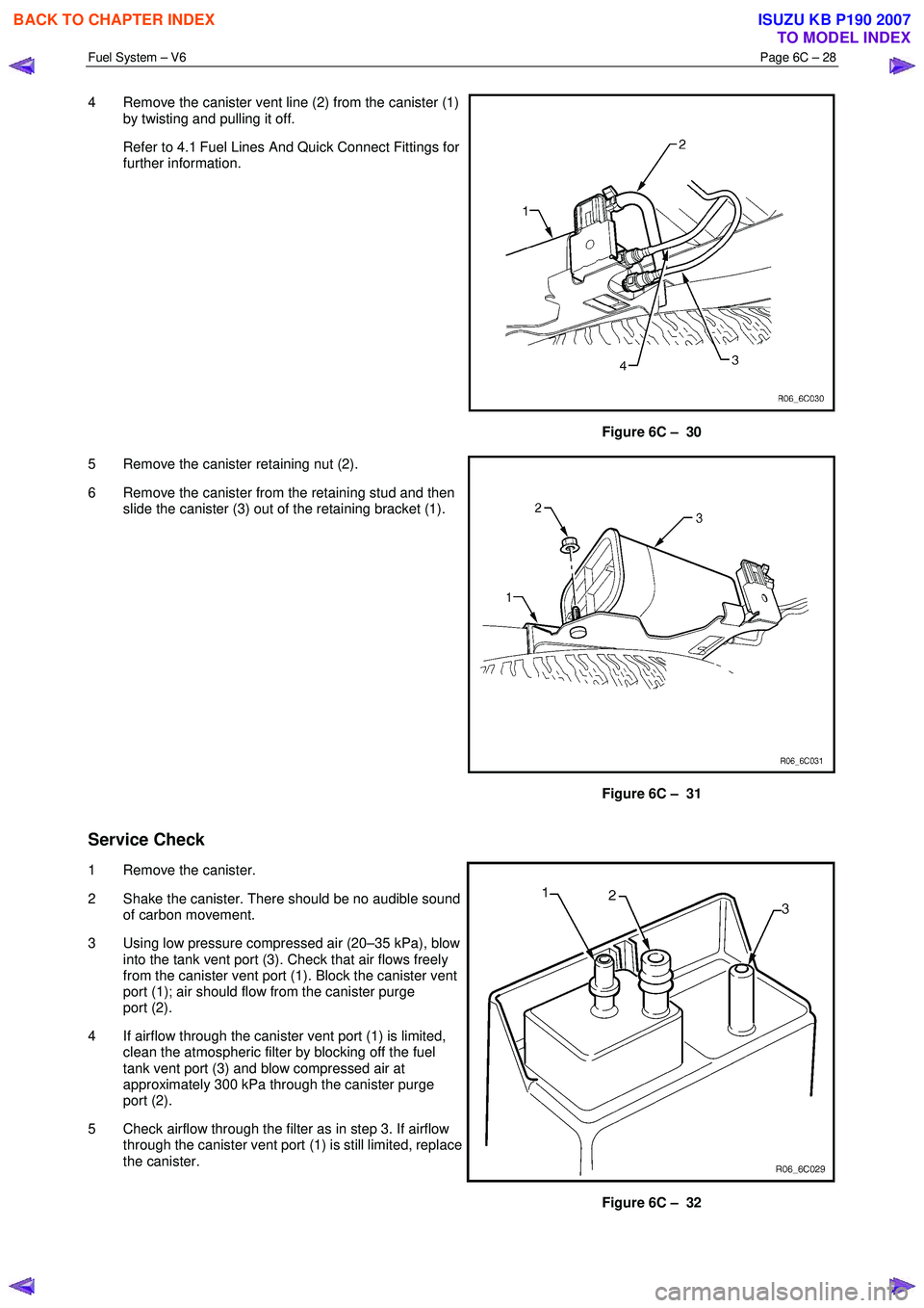
4 Remove the canister vent line (2) from the canister (1)
by twisting and pulling it off.
Refer to 4.1 Fuel Lines And Quick Connect Fittings for further information.
Figure 6C – 30
5 Remove the canister retaining nut (2).
6 Remove the canister from the retaining stud and then slide the canister (3) out of the retaining bracket (1).
Figure 6C – 31
Service Check
1 Remove the canister.
2 Shake the canister. There should be no audible sound of carbon movement.
3 Using low pressure compressed air (20–35 kPa), blow into the tank vent port (3). Check that air flows freely
from the canister vent port (1). Block the canister vent
port (1); air should flow from the canister purge
port (2).
4 If airflow through the canister vent port (1) is limited, clean the atmospheric filter by blocking off the fuel
tank vent port (3) and blow compressed air at
approximately 300 kPa through the canister purge
port (2).
5 Check airflow through the filter as in step 3. If airflow through the canister vent port (1) is still limited, replace
the canister.
Figure 6C – 32
BACK TO CHAPTER INDEX
TO MODEL INDEX
ISUZU KB P190 2007
Page 3232 of 6020
Fuel System – V6 Page 6C – 30
4.7 Fuel Tank Siphon Procedure
• Fuel vapour remains in the modular fuel
pump and sender assembly and fuel lines
that can be spilled during service
operations. Ensure no naked flames or
other ignition sources are nearby. Ensure
all cellular phones (and transmission
devices that may cause any metal objects
to become unintentional receiving
antennas) are switched off.
• Place a dry chemical (Class B) fire
extinguisher nearby before performing any
on-vehicle service procedures. Failure to
follow these precautions may result in
personal injury.
For an exploded view of fuel tank components, refer Figure 6C – 17.
1 Depressurise the fuel system, refer to 3.4 Fuel System Depressurisation.
2 Reinstall the fuel pump relay, refer to 8A Electrical Body and Chassis.
Disconnecting the battery affects certain
vehicle electronic systems. 1.1 WARNING,
CAUTION and NOTES.
3 Disconnect the negative battery terminal.
4 Remove the fuel filler cap.
NOTE
Lubricate the fuel siphon hose with J36850
TransJel Transmission Assembly Lubricant or
equivalent to aid hose insertion. Use only an
approved lubricant.
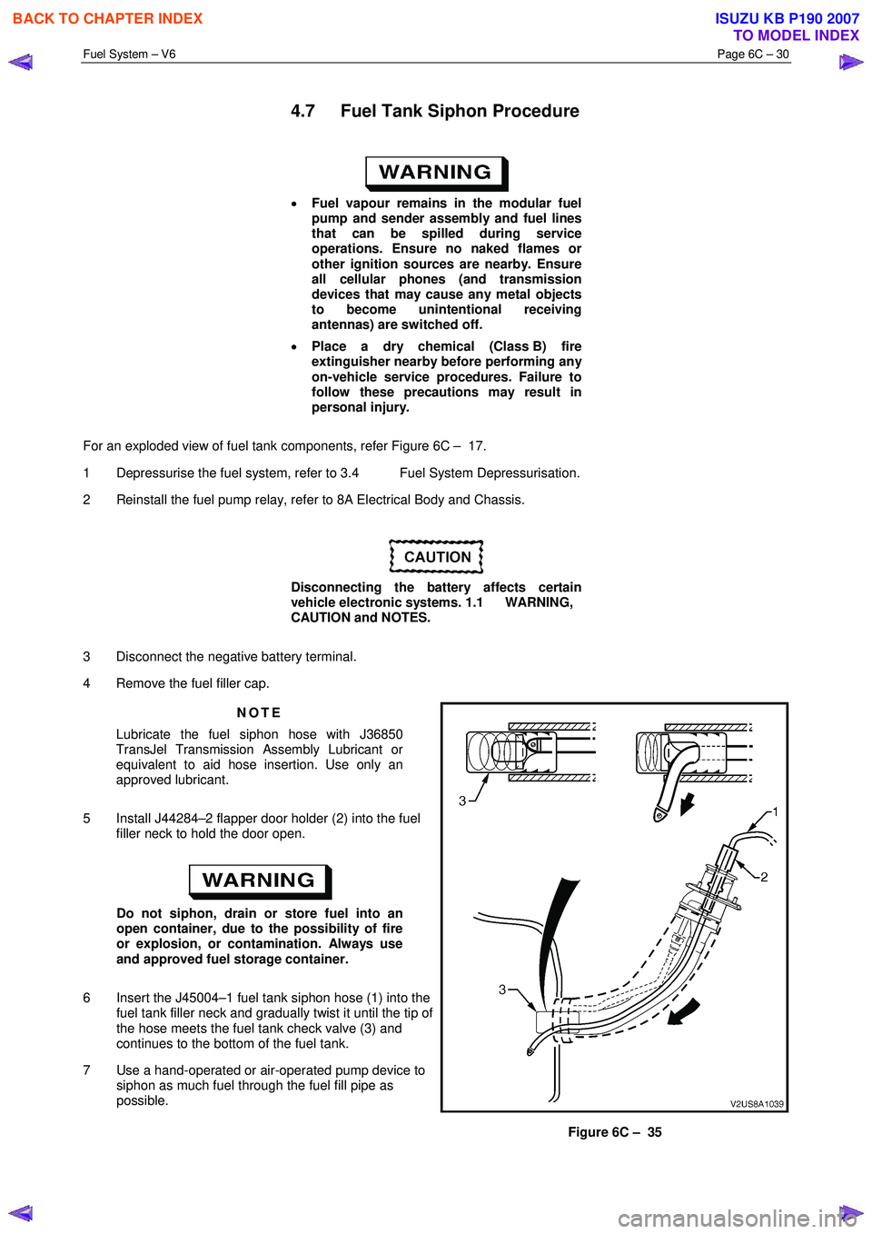
5 Install J44284–2 flapper door holder (2) into the fuel filler neck to hold the door open.
Do not siphon, drain or store fuel into an
open container, due to the possibility of fire
or explosion, or contamination. Always use
and approved fuel storage container.
6 Insert the J45004–1 fuel tank siphon hose (1) into the fuel tank filler neck and gradually twist it until the tip of
the hose meets the fuel tank check valve (3) and
continues to the bottom of the fuel tank.
7 Use a hand-operated or air-operated pump device to siphon as much fuel through the fuel fill pipe as
possible.
Figure 6C – 35
BACK TO CHAPTER INDEX
TO MODEL INDEX
ISUZU KB P190 2007
Page 3234 of 6020
Fuel System – V6 Page 6C – 32
4.8 Fuel Filler Cap
The fuel filler cap is a 'screw on' type, with an integrated tightening torque limiting mechanism. W hen installing the fuel
filler cap, tighten it until a ratcheting (clicking) sound is audible, indicating the fuel filler cap is properly tightened. Th e fuel
filler cap is tethered to the fuel filler pocket.
Remove
The fuel filler cap requires a quarter of a turn anticlockwise to be removed.
Vacuum and pressure valves are built into the fuel filler cap
which regulate the pressure in the fuel tank and prevent fuel
tank and system damage.
Inspection
Inspect the fuel filler cap and seal for any signs of damage.
Replace the fuel filler cap if found to be defective.
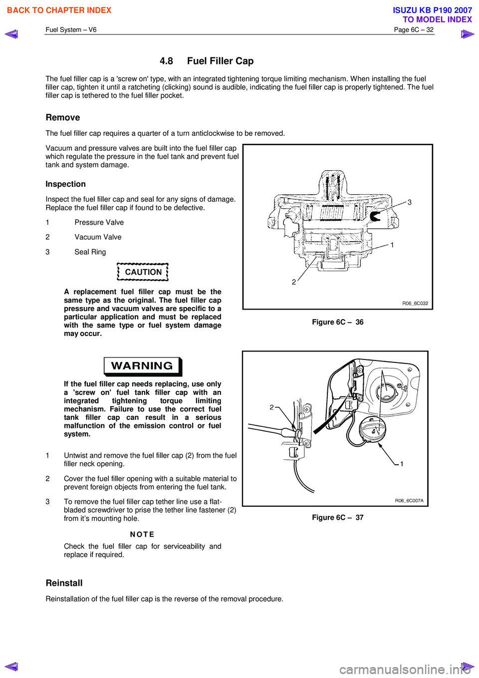
1 Pressure Valve
2 Vacuum Valve
3 Seal Ring
A replacement fuel filler cap must be the
same type as the original. The fuel filler cap
pressure and vacuum valves are specific to a
particular application and must be replaced
with the same type or fuel system damage
may occur.
Figure 6C – 36
If the fuel filler cap needs replacing, use only
a 'screw on' fuel tank filler cap with an
integrated tightening torque limiting
mechanism. Failure to use the correct fuel
tank filler cap can result in a serious
malfunction of the emission control or fuel
system.
1 Untwist and remove the fuel filler cap (2) from the fuel filler neck opening.
2 Cover the fuel filler opening with a suitable material to prevent foreign objects from entering the fuel tank.
3 To remove the fuel filler cap tether line use a flat- bladed screwdriver to prise the tether line fastener (2)
from it’s mounting hole.
NOTE
Check the fuel filler cap for serviceability and
replace if required.
Figure 6C – 37
Reinstall
Reinstallation of the fuel filler cap is the reverse of the removal procedure.
BACK TO CHAPTER INDEX
TO MODEL INDEX
ISUZU KB P190 2007