2007 ISUZU KB P190 service
[x] Cancel search: servicePage 3075 of 6020
Engine Mechanical – V6 Page 6A1–298
Page 6A1–298
Measuring Cylinder Bore Taper
1 Measure the cylinder bore along the thrust surfaces, perpendicular to the crankshaft centreline, at 10 mm below the
deck surface and record the measurement.
2 Measure the cylinder bore along the th rust surfaces, perpendicular to the crankshaft centreline, at 100 mm below
the deck surface and record the measurement.
3 Calculate the difference betw een the two measurements. The re sult will be the cylinder taper.
4 Compare the results with the dimensions listed in the specifications, refer to 5 Specifications.
NOTE
If the cylinder diameter exceeds the
specifications, the cylinder block may be
oversized to 0.25 mm. Only one size of oversized
pistons and rings are available for service. If the
cylinder bore diameter ex ceeds specification by
more than 0.25 mm, the cylinder block must be
replaced.
Measuring Cylinder Bore Out-of-Round
1 Measure both the thrust and non-thrust cylinder diameter at 10 mm below the deck. Record your measurements.
2 Calculate the difference bet ween the two measurements. The result will indicate out-of-r ound at the upper end of
the cylinder.
3 Measure both the thrust and non-thru st cylinder diameter at 100 mm below the deck surface. Record your
measurements.
4 Calculate the difference between the tw o measurements. The result will indicate out-of-round at the lower end of
the cylinder.
5 Compare your results with the dimensions listed in the specifications, refer to 5 Specifications.
NOTE
If the cylinder diameter exceeds the
specifications, the cylinder block may be
oversized to 0.25 mm. Only one size of oversized
pistons and rings are available for service. If the
cylinder bore diameter ex ceeds specification by
more than 0.25 mm, the cylinder block must be
replaced.
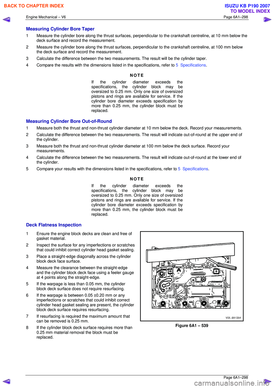
Deck Flatness Inspection
1 Ensure the engine block decks are clean and free of gasket material.
2 Inspect the surface for any imperfections or scratches
that could inhibit correct cylinder head gasket sealing.
3 Place a straight-edge diagonally across the cylinder block deck face surface.
4 Measure the clearance between the straight-edge
and the cylinder block deck face using a feeler gauge
at 4 points along the straight-edge.
5 If the warpage is less t han 0.05 mm, the cylinder
block deck surface does not require resurfacing.
6 If the warpage is between 0.05 ±0.20 mm or any imperfections or scratches that could inhibit correct
cylinder head gasket sealing are present, the cylinder
block deck surface requires resurfacing.
7 If resurfacing is requir ed the maximum amount that
can be removed is 0.25 mm.
8 If the cylinder block deck surface requires more than 0.25 mm material removal the block must be
replaced.
Figure 6A1 – 539
BACK TO CHAPTER INDEX
TO MODEL INDEX
ISUZU KB P190 2007
Page 3124 of 6020
Engine Mechanical – V6 Page 6A1–347
Page 6A1–347
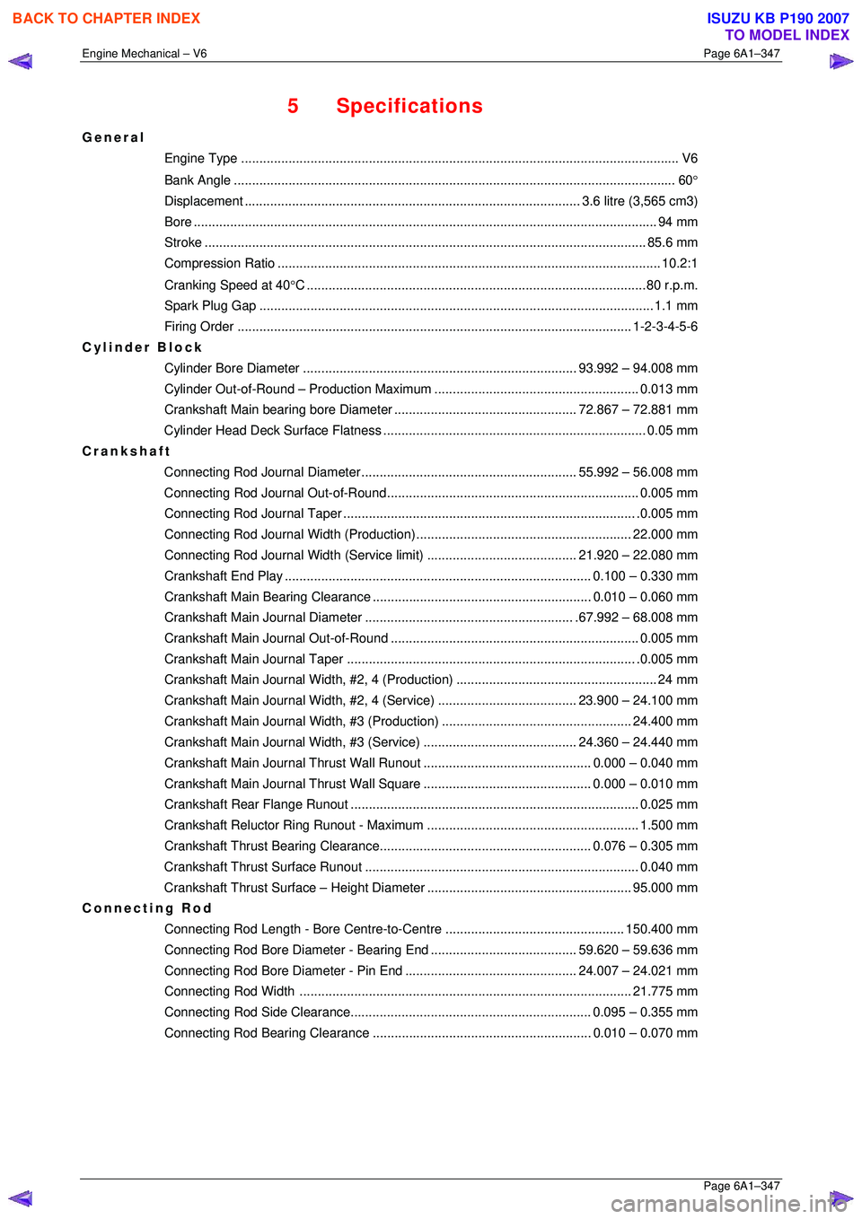
5 Specifications
General
Engine Type .................................................................................................................... .... V6
Bank An gle ..................................................................................................................... .... 60°
Displacement ............................................................................................ 3.6 litre (3,565 cm3)
Bore ........................................................................................................................... .... 94 mm
Stroke ......................................................................................................................... 85.6 mm
Compression Ratio......................................................................................................... 10. 2:1
Cranking Speed at 40 °C .............................................................................................80 r.p.m.
Spark Plug Gap ............................................................................................................ 1.1 mm
Firing Order ............................................................................................................ 1- 2-3-4-5-6
Cylinder Block
Cylinder Bore Diame ter ........................................................................... 93.992 – 94.008 mm
Cylinder Out-of-Round – Pr oduction Maximum ........................................................ 0.013 mm
Crankshaft Main bearing bor e Diameter .................................................. 72. 867 – 72.881 mm
Cylinder Head Deck Surf ace Flatness ........................................................................ 0. 05 mm
Crankshaft
Connecting Rod Journal Diameter........................................................... 55. 992 – 56.008 mm
Connecting Rod Journa l Out-of-Round..................................................................... 0.005 mm
Connecting Rod Jour nal Taper................................................................................ .0. 005 mm
Connecting Rod Journal Width (Production)........................................................... 22.000 mm
Connecting Rod Journal Width (Service limit)......................................... 21. 920 – 22.080 mm
Crankshaft End Pl ay .................................................................................... 0.100 – 0.330 mm
Crankshaft Main Bearing Clearance ............................................................ 0.010 – 0.060 mm
Crankshaft Main Journal Diameter......................................................... .67. 992 – 68.008 mm
Crankshaft Main Journa l Out-of-Round .................................................................... 0.005 mm
Crankshaft Main Journal Taper ............................................................................... .0. 005 mm
Crankshaft Main Journal Width, #2, 4 (Pr oduction)....................................................... 24 mm
Crankshaft Main Journal Width, #2, 4 (Service)...................................... 23. 900 – 24.100 mm
Crankshaft Main Journal Wi dth, #3 (Production) .................................................... 24.400 mm
Crankshaft Main Journal Width, #3 (Service).......................................... 24. 360 – 24.440 mm
Crankshaft Main Journal Thru st Wall Runout.............................................. 0.
000 – 0.040 mm
Crankshaft Main Journal Thru st Wall Square.............................................. 0. 000 – 0.010 mm
Crankshaft Rear Fl ange Runout............................................................................... 0. 025 mm
Crankshaft Reluctor Ring Ru nout - Maximum .......................................................... 1.500 mm
Crankshaft Thrust Bearin g Clearance.......................................................... 0. 076 – 0.305 mm
Crankshaft Thrust Su rface Runout........................................................................... 0. 040 mm
Crankshaft Thrust Surface – Height Diameter ........................................................ 95.000 mm
Connecting Rod
Connecting Rod Length - Bore Centre-to-Centre ................................................. 150.400 mm
Connecting Rod Bore Diameter - Bearing End........................................ 59. 620 – 59.636 mm
Connecting Rod Bore Diamet er - Pin End............................................... 24. 007 – 24.021 mm
Connecting Rod Width ........................................................................................... 21.775 mm
Connecting Rod Side Cl earance.................................................................. 0.095 – 0.355 mm
Connecting Rod Bearing Clearance ............................................................ 0.010 – 0.070 mm
BACK TO CHAPTER INDEX
TO MODEL INDEX
ISUZU KB P190 2007
Page 3136 of 6020
Engine Cooling – V6 Engine Page 6B1–1
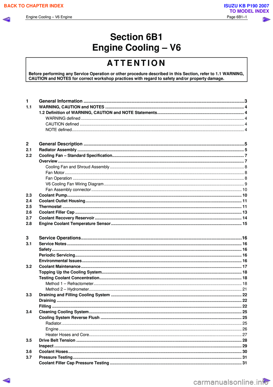
Section 6B1
Engine Cooling – V6
ATTENTION
Before performing any Service Operation or other procedure described in this Section, refer to 1.1 WARNING,
CAUTION and NOTES for correct workshop practices with regard to safety and/or property damage.
1 General Information ............................................................................................................ ...................3
1.1 WARNING, CAUTION and NOTES ..................................................................................................... ................... 4
1.2 Definition of WARNING, CAUTION and NOTE Statements ......................................................................... .. 4
WARNING defined ............................................................................................................................................. 4
CAUTION defined .............................................................................................................................................. 4
NOTE defined..................................................................................................................................................... 4
2 General Description ............................................................................................................ ...................5
2.1 Radiator Assembly .............................................................................................................. .................................. 5
2.2 Cooling Fan – Standard Specification.................................................................................................................. 7
Overview ................................................................................................................................................................. 7
Cooling Fan and Shroud Assembly ................................................................................................ .................... 8
Fan Motor ........................................................................................................................................................... 8
Fan Operation .................................................................................................................. .................................. 8
V6 Cooling Fan Wiring Diagram .................................................................................................. ....................... 9
Fan Assembly connector .................................................................................................................................. 10
2.3 Coolant Pump....................................................................................................................................................... 10
2.4 Coolant Outlet Housing ......................................................................................................... .............................. 11
2.5 Thermostat ........................................................................................................................................................... 11
2.6 Coolant Filler Cap ............................................................................................................. ................................... 13
2.7 Coolant Recovery Reservoir ..................................................................................................... .......................... 14
2.8 Engine Coolant Temperature Sensor .............................................................................................. ................... 15
3 Service Operations ...............................................................................................................................16
3.1 Service Notes ....................................................................................................................................................... 16
Safety .................................................................................................................................................................... 16
Periodic Servicing............................................................................................................. ................................... 16
Environmental Issues ........................................................................................................... ............................... 16
3.2 Coolant Maintenance ........................................................................................................................................... 17
Topping Up the Cooling System.................................................................................................. ....................... 18
Testing Coolant Concentration........................................................................................................................... 18
Method 1 – Refractometer................................................................................................................................ 18
Method 2 – Hydrometer.................................................................................................................................... 21
3.3 Draining and Filling Cooling System ............................................................................................ ..................... 22
Draining ................................................................................................................................................................ 22
Filling .................................................................................................................................................................... 22
3.4 Cleaning Cooling System ........................................................................................................ ............................ 25
Cooling System Reverse Flush ................................................................................................... ....................... 25
Radiator............................................................................................................................................................ 25
Engine .............................................................................................................................................................. 26
Heater Hoses and Core.......................................................................................................... .......................... 27
3.5 Drive Belt Tension ............................................................................................................................................... 28
Inspect .................................................................................................................................................................. 29
3.6 Coolant Hoses ...................................................................................................................................................... 30
3.7 Pressure Testing ............................................................................................................... ................................... 31
Coolant Filler Cap Pressure Testing ............................................................................................ ...................... 31
BACK TO CHAPTER INDEX
TO MODEL INDEX
ISUZU KB P190 2007
Page 3139 of 6020
Engine Cooling – V6 Engine Page 6B1–4
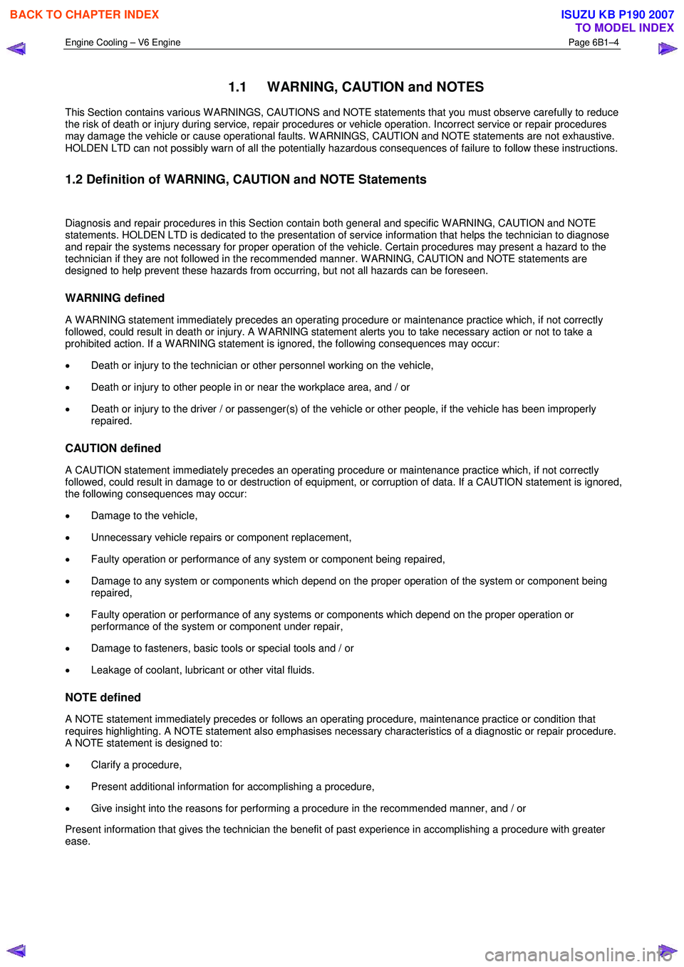
1.1 WARNING, CAUTION and NOTES
This Section contains various W ARNINGS, CAUTIONS and NOTE statements that you must observe carefully to reduce
the risk of death or injury during service, repair procedures or vehicle operation. Incorrect service or repair procedures
may damage the vehicle or cause operational faults. W ARNINGS, CAUTION and NOTE statements are not exhaustive.
HOLDEN LTD can not possibly warn of all the potentially hazardous consequences of failure to follow these instructions.
1.2 Definition of WARNING, CAUTION and NOTE Statements
Diagnosis and repair procedures in this Section contain both general and specific W ARNING, CAUTION and NOTE
statements. HOLDEN LTD is dedicated to the presentation of service information that helps the technician to diagnose
and repair the systems necessary for proper operation of the vehicle. Certain procedures may present a hazard to the
technician if they are not followed in the recommended manner. W ARNING, CAUTION and NOTE statements are
designed to help prevent these hazards from occurring, but not all hazards can be foreseen.
WARNING defined
A W ARNING statement immediately precedes an operating procedure or maintenance practice which, if not correctly
followed, could result in death or injury. A W ARNING statement alerts you to take necessary action or not to take a
prohibited action. If a W ARNING statement is ignored, the following consequences may occur:
• Death or injury to the technician or other personnel working on the vehicle,
• Death or injury to other people in or near the workplace area, and / or
• Death or injury to the driver / or passenger(s) of the vehicle or other people, if the vehicle has been improperly
repaired.
CAUTION defined
A CAUTION statement immediately precedes an operating procedure or maintenance practice which, if not correctly
followed, could result in damage to or destruction of equipment, or corruption of data. If a CAUTION statement is ignored,
the following consequences may occur:
• Damage to the vehicle,
• Unnecessary vehicle repairs or component replacement,
• Faulty operation or performance of any system or component being repaired,
• Damage to any system or components which depend on the proper operation of the system or component being
repaired,
• Faulty operation or performance of any systems or components which depend on the proper operation or
performance of the system or component under repair,
• Damage to fasteners, basic tools or special tools and / or
• Leakage of coolant, lubricant or other vital fluids.
NOTE defined
A NOTE statement immediately precedes or follows an operating procedure, maintenance practice or condition that
requires highlighting. A NOTE statement also emphasises necessary characteristics of a diagnostic or repair procedure.
A NOTE statement is designed to:
• Clarify a procedure,
• Present additional information for accomplishing a procedure,
• Give insight into the reasons for performing a procedure in the recommended manner, and / or
Present information that gives the technician the benefit of past experience in accomplishing a procedure with greater
ease.
BACK TO CHAPTER INDEX
TO MODEL INDEX
ISUZU KB P190 2007
Page 3140 of 6020
Engine Cooling – V6 Engine Page 6B1–5
2 General Description
2.1 Radiator Assembly
The radiator has an aluminium core and is of the cross-flow design. Plastic side tanks are attached to the core by clinch
tabs. The clinch tabs are formed as part of the core assembly.
The lower frame of the radiator assembly is attached to the vehicle frame by two bolts supported in rubber mounts, pegs
are attached to the upper area of each side tank. These pegs are used to support the radiator with two rubber insert
mounting brackets.
A high temperature rubber seal is used to seal the mating surface between the core and each side tank. The seal(s)
must be replaced any time the side tank is removed from the core.
NOTE
The radiator core side tanks or transmission oil
cooler cannot be replaced separately. If there is a
fault with any of these components, the radiator
assembly must be replaced. Small core repairs
may be made using an aluminised silicon based
liquid repair agent. Refer to 3.15 Radiator in
this Section.
For vehicles with automatic transmission, a transmission oil cooler is located in the right-hand side radiator tank. The
cooler pipes from and to the transmission are connected to the oil cooler flexible hoses by means of quick connect
fittings.
The cooling fan motor is attached by three screws to the one-piece plastic fan shroud. In turn, the fan shroud is mounted
to the rear of the radiator and is located and supported by two bolts and two locating tabs. The upper clips lock the fan
shroud in place and can be released by hand to facilitate fan shroud removal. The shroud must be removed to allow fan
motor and blade assembly removal.
One harness connector is mounted to the upper section of the fan shroud allowing the fan motor and blade assemblies
to be removed individually from the shroud. The fan motor and blade is balanced as an assembly. These two
components are serviced only as a unit and are not to be separated.
The shroud, fan assembly and transmission cooler hoses can be removed and installed individually from the vehicle. For
removal and installation procedures, refer to 3.13Cooling Fan and Shroud Assembly, 3.14 Flexible Transmission
Cooler Hose and 3.15 Radiator in this Section.
BACK TO CHAPTER INDEX
TO MODEL INDEX
ISUZU KB P190 2007
Page 3143 of 6020
Engine Cooling – V6 Engine Page 6B1–8
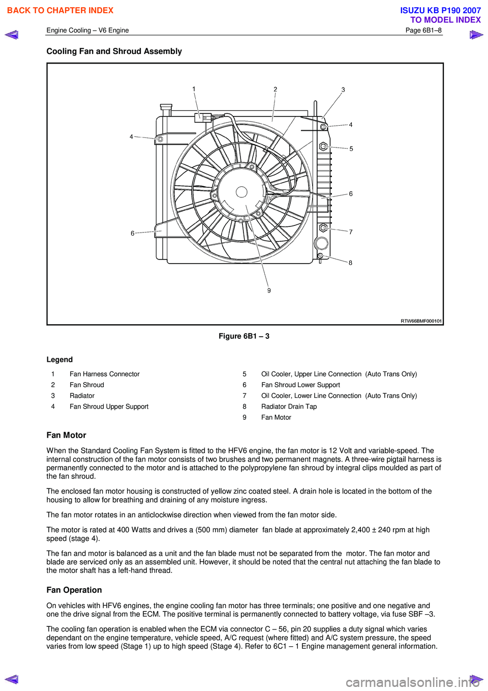
Cooling Fan and Shroud Assembly
Figure 6B1 – 3
Legend
1 Fan Harness Connector
2 Fan Shroud
3 Radiator
4 Fan Shroud Upper Support 5 Oil Cooler, Upper Line Connection (Auto Trans Only)
6 Fan Shroud Lower Support
7 Oil Cooler, Lower Line Connection (Auto Trans Only)
8 Radiator Drain Tap
9 Fan Motor
Fan Motor
W hen the Standard Cooling Fan System is fitted to the HFV6 engine, the fan motor is 12 Volt and variable-speed. The
internal construction of the fan motor consists of two brushes and two permanent magnets. A three-wire pigtail harness is
permanently connected to the motor and is attached to the polypropylene fan shroud by integral clips moulded as part of
the fan shroud.
The enclosed fan motor housing is constructed of yellow zinc coated steel. A drain hole is located in the bottom of the
housing to allow for breathing and draining of any moisture ingress.
The fan motor rotates in an anticlockwise direction when viewed from the fan motor side.
The motor is rated at 400 W atts and drives a (500 mm) diameter fan blade at approximately 2,400 ± 240 rpm at high
speed (stage 4).
The fan and motor is balanced as a unit and the fan blade must not be separated from the motor. The fan motor and
blade are serviced only as an assembled unit. However, it should be noted that the central nut attaching the fan blade to
the motor shaft has a left-hand thread.
Fan Operation
On vehicles with HFV6 engines, the engine cooling fan motor has three terminals; one positive and one negative and
one the drive signal from the ECM. The positive terminal is permanently connected to battery voltage, via fuse SBF –3.
The cooling fan operation is enabled when the ECM via connector C – 56, pin 20 supplies a duty signal which varies
dependant on the engine temperature, vehicle speed, A/C request (where fitted) and A/C system pressure, the speed
varies from low speed (Stage 1) up to high speed (Stage 4). Refer to 6C1 – 1 Engine management general information.
BACK TO CHAPTER INDEX
TO MODEL INDEX
ISUZU KB P190 2007
Page 3151 of 6020

Engine Cooling – V6 Engine Page 6B1–16
3 Service Operations
3.1 Service Notes
Safety
• To avoid serious personal injury, never
remove the coolant filler pressure cap on
the coolant outlet housing when the
engine is hot, even if the cooling system
should require filling. Sudden release of
cooling system pressure is very
dangerous.
• The vehicle is fitted with an electric
radiator cooling fan. When working around
the engine compartment, keep clear of the
fan as it may start without warning.
Before removing the coolant filler cap, allow the engine to cool, then place a shop rag over the coolant filler cap and then
slowly turn the cap anticlockwise, approximately 1½ turns, until the pressure relief position is reached. The pressure
relief position will allow any remaining pressure within the system to escape into the coolant recovery reservoir. Continue
to rotate the cap anticlockwise until the cap can be safely removed.
Periodic Servicing
The cooling system requires little attention except for maintaining the coolant to the correct level in the recovery reservoir
and periodic servicing at the time or distance intervals as outlined in 0B Lubrication and Service.
Periodic servicing includes:
1 Checking coolant level. Refer to 3.3 Draining and Filling Cooling System in this Section.
2 Checking coolant concentration. Refer to 3.2 Coolant Maintenance – Testing Coolant Concentration in this Section.
3 Pressure test cooling system and coolant filler cap. Refer to 3.7 Pressure Testing in this Section.
4 Tighten hose clamps and inspect all hoses. Refer to 3.6 Coolant Hoses in this Section. Replace hoses if swollen or deteriorated.
Always wear protective safety glasses when
working with spring type hose clamps. Failure
to do so could result in eye injury.
5 Clean out cooling system, refer to 3.4 Cleaning Cooling System – Cooling System Flush, in this Section and refill. Refer to 3.3 Draining and Filling Cooling System in this Section.
Environmental Issues
To reduce environmental impact and maintenance cost, whenever the coolant is drained from any engine, the service
records are to be checked to determine when the coolant was last changed. If more than six months life is left before the
next coolant change, then the following procedure is to be followed:
1 W hen draining the coolant from the engine, use a clean container to hold at least 12 litres of coolant and ensure that the coolant is not contaminated in the draining process.
2 After repairs have been completed, refill the engine cooling system with the drained coolant.
BACK TO CHAPTER INDEX
TO MODEL INDEX
ISUZU KB P190 2007
Page 3153 of 6020
Engine Cooling – V6 Engine Page 6B1–18
Topping Up the Cooling System
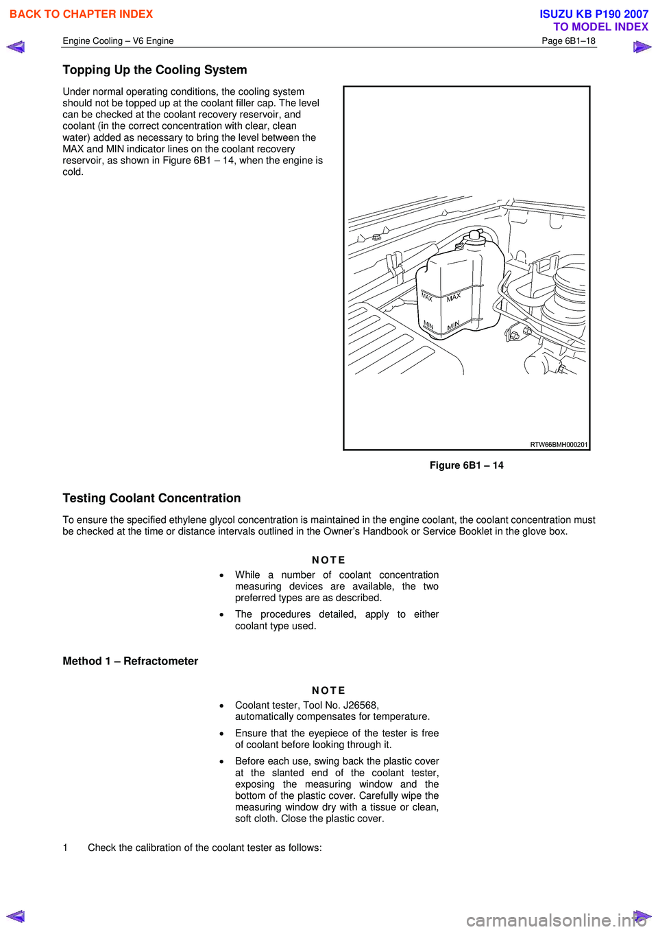
Under normal operating conditions, the cooling system
should not be topped up at the coolant filler cap. The level
can be checked at the coolant recovery reservoir, and
coolant (in the correct concentration with clear, clean
water) added as necessary to bring the level between the
MAX and MIN indicator lines on the coolant recovery
reservoir, as shown in Figure 6B1 – 14, when the engine is
cold.
Figure 6B1 – 14
Testing Coolant Concentration
To ensure the specified ethylene glycol concentration is maintained in the engine coolant, the coolant concentration must
be checked at the time or distance intervals outlined in the Owner’s Handbook or Service Booklet in the glove box.
NOTE
• While a number of coolant concentration
measuring devices are available, the two
preferred types are as described.
• The procedures detailed, apply to either
coolant type used.
Method 1 – Refractometer
NOTE
• Coolant tester, Tool No. J26568,
automatically compensates for temperature.
• Ensure that the eyepiece of the tester is free
of coolant before looking through it.
• Before each use, swing back the plastic cover
at the slanted end of the coolant tester,
exposing the measuring window and the
bottom of the plastic cover. Carefully wipe the
measuring window dry with a tissue or clean,
soft cloth. Close the plastic cover.
1 Check the calibration of the coolant tester as follows:
BACK TO CHAPTER INDEX
TO MODEL INDEX
ISUZU KB P190 2007