2007 ISUZU KB P190 ECO mode
[x] Cancel search: ECO modePage 3599 of 6020
Charging System – V6 Page 6D1-1-12
7 Reconnect the battery ground cable P-5.
8 Fit a loading device (7) across the battery terminals, e.g. an adjustable carbon pile.
The loading device must have a minimum
power consumption of 1000 W.
9 Record the voltage reading before starting the engine. (This reading should increase when the engine is running, indicating generator output.).
10 Start the engine.
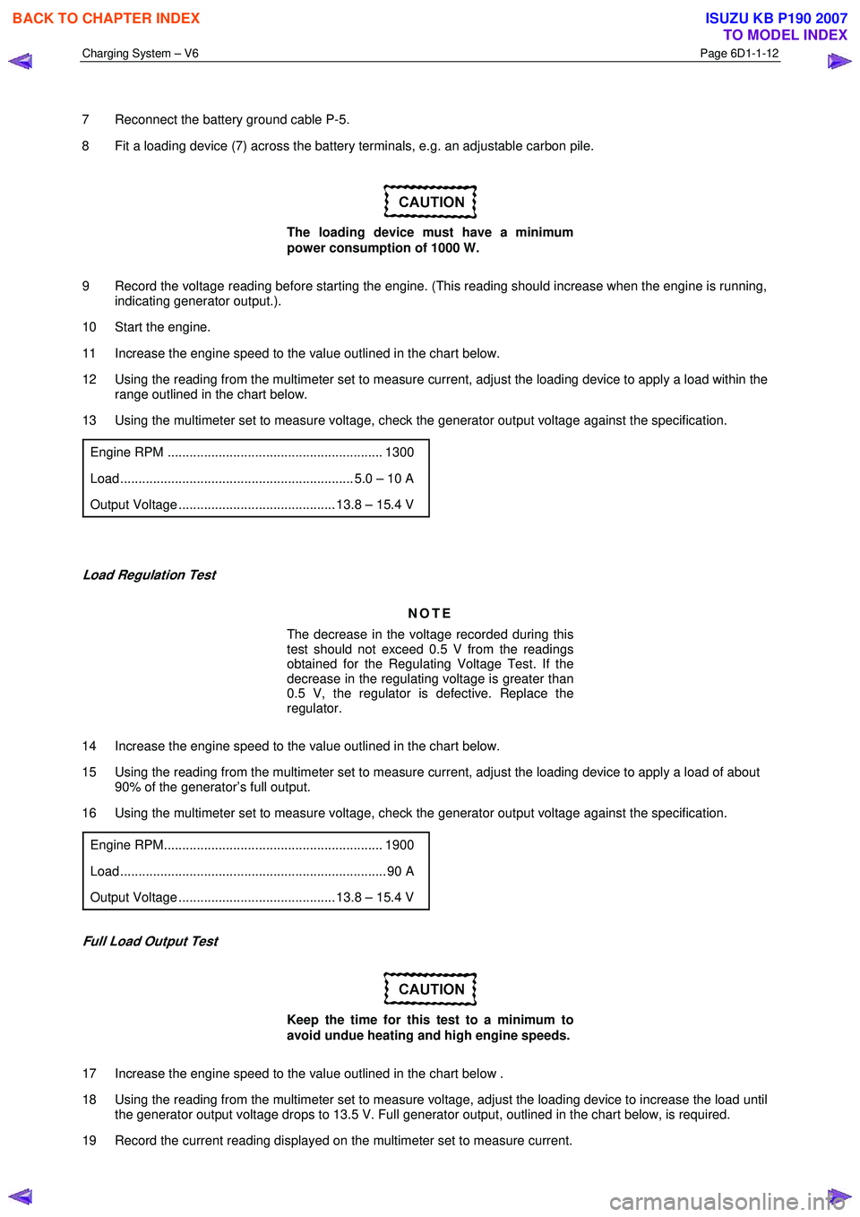
11 Increase the engine speed to the value outlined in the chart below.
12 Using the reading from the multimeter set to measure current, adjust the loading device to apply a load within the range outlined in the chart below.
13 Using the multimeter set to measure voltage, check the generator output voltage against the specification.
Engine RPM ........................................................... 1300
Load ................................................................ 5.0 – 10 A
Output Voltage ........................................... 13.8 – 15.4 V
Load Regulation Test
NOTE
The decrease in the voltage recorded during this
test should not exceed 0.5 V from the readings
obtained for the Regulating Voltage Test. If the
decrease in the regulating voltage is greater than
0.5 V, the regulator is defective. Replace the
regulator.
14 Increase the engine speed to the value outlined in the chart below.
15 Using the reading from the multimeter set to measure current, adjust the loading device to apply a load of about 90% of the generator’s full output.
16 Using the multimeter set to measure voltage, check the generator output voltage against the specification.
Engine RPM............................................................ 1900
Load ......................................................................... 90 A
Output Voltage ........................................... 13.8 – 15.4 V
Full Load Output Test
Keep the time for this test to a minimum to
avoid undue heating and high engine speeds.
17 Increase the engine speed to the value outlined in the chart below .
18 Using the reading from the multimeter set to measure voltage, adjust the loading device to increase the load until the generator output voltage drops to 13.5 V. Full generator output, outlined in the chart below, is required.
19 Record the current reading displayed on the multimeter set to measure current.
BACK TO CHAPTER INDEX
TO MODEL INDEX
ISUZU KB P190 2007
Page 3600 of 6020
Charging System – V6 Page 6D1-1-13
20 Reduce the engine speed to idle.
On completion of the generator output test,
return the engine to idle and disconnect the
loading device from the battery terminals.
This prevents excessive battery discharge.
21 Stop the engine.
22 Disconnect the battery ground cable P-5 at the battery.
23 Remove the multimeters.
24 Reconnect the generator positive lead P-9.
25 Reconnect the battery ground cable P-5 to the battery.
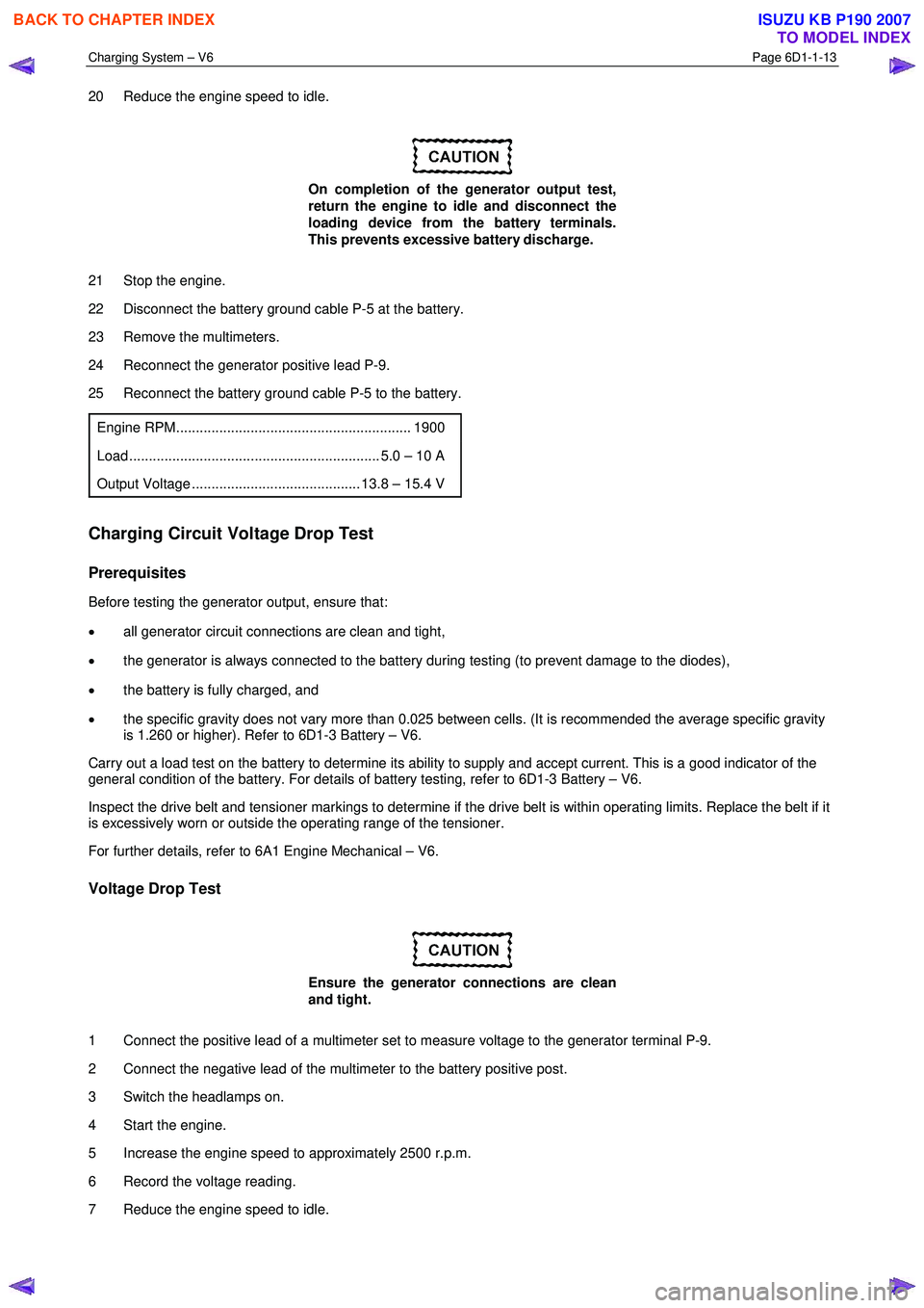
Engine RPM............................................................ 1900
Load ................................................................ 5.0 – 10 A
Output Voltage ........................................... 13.8 – 15.4 V
Charging Circuit Voltage Drop Test
Prerequisites
Before testing the generator output, ensure that:
• all generator circuit connections are clean and tight,
• the generator is always connected to the battery during testing (to prevent damage to the diodes),
• the battery is fully charged, and
• the specific gravity does not vary more than 0.025 between cells. (It is recommended the average specific gravity
is 1.260 or higher). Refer to 6D1-3 Battery – V6.
Carry out a load test on the battery to determine its ability to supply and accept current. This is a good indicator of the
general condition of the battery. For details of battery testing, refer to 6D1-3 Battery – V6.
Inspect the drive belt and tensioner markings to determine if the drive belt is within operating limits. Replace the belt if it
is excessively worn or outside the operating range of the tensioner.
For further details, refer to 6A1 Engine Mechanical – V6.
Voltage Drop Test
Ensure the generator connections are clean
and tight.
1 Connect the positive lead of a multimeter set to measure voltage to the generator terminal P-9.
2 Connect the negative lead of the multimeter to the battery positive post.
3 Switch the headlamps on.
4 Start the engine.
5 Increase the engine speed to approximately 2500 r.p.m.
6 Record the voltage reading.
7 Reduce the engine speed to idle.
BACK TO CHAPTER INDEX
TO MODEL INDEX
ISUZU KB P190 2007
Page 3601 of 6020

Charging System – V6 Page 6D1-1-14
8 Connect the positive lead of a multimeter set to measure voltage to the battery negative post.
9 Connect the negative lead of the multimeter to the generator housing.
9 Increase the engine speed to approximately 2500 r.p.m.
10 Record the voltage reading.
11 Reduce the engine speed to idle.
12 Check the two readings. If the readings exceed 0.3 V, there is a high resistance in the charging circuit.
13 Trace the cause and correct the problem, refer to 8A Electrical Body and Chassis.
BACK TO CHAPTER INDEX
TO MODEL INDEX
ISUZU KB P190 2007
Page 3603 of 6020
Charging System – V6 Page 6D1-1-16
Reinstall
Reinstallation of the generator is the reverse of the removal procedure, noting the following:
1 Tighten all fasteners to the correct torque specification.
2 Reconnect the battery ground lead.
3 Start the engine.
4 Check the generator warning indicator operation.
5 Check the drive belt is correctly routed and aligned.
6 Check the generator output. Refer to 3.3 On-vehicle Testing.
7 Check the voltage regulator operation. Refer to 3.3 On-vehicle Testing.
8 Turn the ignition switch off.
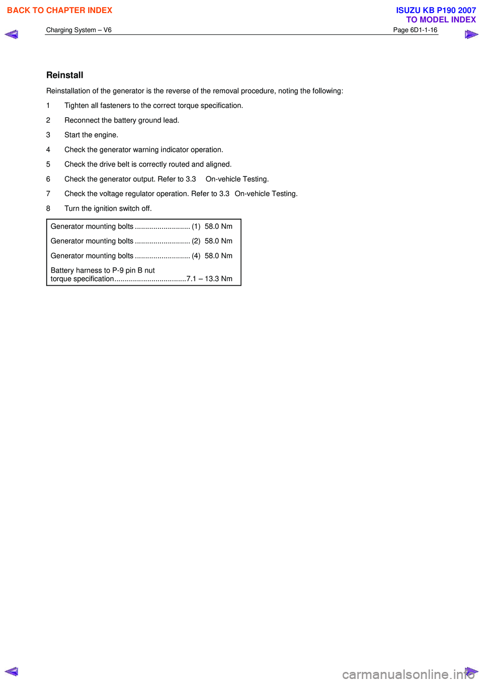
Generator mounting bolts ........................... (1) 58.0 Nm
Generator mounting bolts ........................... (2) 58.0 Nm
Generator mounting bolts ........................... (4) 58.0 Nm
Battery harness to P-9 pin B nut
torque specification ...................................7.1 – 13.3 Nm
BACK TO CHAPTER INDEX
TO MODEL INDEX
ISUZU KB P190 2007
Page 3611 of 6020
Starting System – V6 Page 6D1-2–3
1 General Information
All HFV6 engines are fitted with a Mitsubishi starter motor. This consists of a solenoid switch on a DC motor. The motor
has permanent magnet excitation, which has the advantage of low weight a with high output torque and is visually
identifiable by the absence of pole-shoe retaining screws.
The starter motor does not have field coil windings or pole shoes. These parts have been replaced by six permanent
magnets that are held in the pole housing by clips. The positive brushes are now part of the brush plate assembly.
The solenoid switch is the only component of the starter motor assembly that is serviced separately. If any other parts
require replacement, the starter motor must be replaced.
1.1 WARNING, CAUTION and NOTES
This Section contains various W ARNINGS, CAUTIONS and NOTE statements that you must observe carefully to reduce
the risk of death or injury during service, repair procedures or vehicle operation. Incorrect service or repair procedures
may damage the vehicle or cause operational faults. W ARNINGS, CAUTION and NOTE statements are not exhaustive.
HOLDEN LTD can not possibly warn of all the potentially hazardous consequences of failure to follow these instructions.
Definition of WARNING, CAUTION and NOTE Statements
Diagnosis and repair procedures in this Section contain both general and specific W ARNING, CAUTION and NOTE
statements. HOLDEN LTD is dedicated to the presentation of service information that helps the technician to diagnose
and repair the systems necessary for proper operation of the vehicle. Certain procedures may present a hazard to the
technician if they are not followed in the recommended manner. W ARNING, CAUTION and NOTE statements are
designed to help prevent these hazards from occurring, but not all hazards can be foreseen.
WARNING defined
A W ARNING statement immediately precedes an operating procedure or maintenance practice which, if not correctly
followed, could result in death or injury. A W ARNING statement alerts you to take necessary action or not to take a
prohibited action. If a W ARNING statement is ignored, the following consequences may occur:
• Death or injury to the technician or other personnel working on the vehicle,
• Death or injury to other people in or near the workplace area, and / or
• Death or injury to the driver / or passenger(s) of the vehicle or other people, if the vehicle has been improperly
repaired.
CAUTION defined
A CAUTION statement immediately precedes an operating procedure or maintenance practice which, if not correctly
followed, could result in damage to or destruction of equipment, or corruption of data. If a CAUTION statement is ignored,
the following consequences may occur:
• Damage to the vehicle,
• Unnecessary vehicle repairs or component replacement,
• Faulty operation or performance of any system or component being repaired,
• Damage to any system or components which depend on the proper operation of the system or component being
repaired,
• Faulty operation or performance of any systems or components which depend on the proper operation or
performance of the system or component under repair,
• Damage to fasteners, basic tools or special tools and / or
• Leakage of coolant, lubricant or other vital fluids.
NOTE defined
A NOTE statement immediately precedes or follows an operating procedure, maintenance practice or condition that
requires highlighting. A NOTE statement also emphasises necessary characteristics of a diagnostic or repair procedure.
A NOTE statement is designed to:
BACK TO CHAPTER INDEX
TO MODEL INDEX
ISUZU KB P190 2007
Page 3612 of 6020
Starting System – V6 Page 6D1-2–4
• Clarify a procedure,
• Present additional information for accomplishing a procedure,
• Give insight into the reasons for performing a procedure in the recommended manner, and / or
Present information that gives the technician the benefit of past experience in accomplishing a procedure with greater
ease.
1.2 Components
Starting System Components
The main components of the starting system are:
• battery,
• wiring,
• ignition switch,
• theft deterrent engine crank inhibitor (a function of the theft deterrent system),
• park / neutral and back-up switch (on vehicles with 4 speed automatic transmission),
• engine control module (ECM),
• start relay,
• solenoid switch, and
• starter motor.
Starter Motor and Solenoid Switch Components
Solenoid Switch
The solenoid switch is used to activate the DC motor and has two windings; the pull-in winding and the hold-in winding.
The pull-in winding has heavier wire and is grounded through the DC motor winding and brushes. The hold-in winding is
grounded through the solenoid casing.
Planetary Drive Train
The planetary drive train consists of an internally toothed ring gear and three planetary gear wheels, which rotate on
sleeve bearings on the planetary drive shaft. The ring gear is keyed into the drive-end housing and is made from
high-grade polyamide with mineral additives.
W hen the starter motor operates, the armature turns the planetary gears inside the fixed planetary ring gear. This drives
the planetary shaft at a reduced speed ratio which turns the drive assembly. A fork lever in the drive-end housing forces
the drive assembly forward to engage with the flexplate / flywheel ring gear on the engine and transmit cranking torque.
An internal clutch allows the drive assembly pinion gear to rotate freely when the engine starts. This prevents the
armature from being driven at excessive speed by the engine.
Armature
The armature shaft is supported at each end by oil absorbent, sintered metal bushes; one in the commutator end shield
and one in the planetary drive shaft. The front end of the armature has a gear profile. This meshes with the three
planetary gear wheels. These in turn, mesh with the internal teeth of the ring gear.
Brushes
A brush plate supports four commutator brushes. This plate is fixed to the commutator end shield with two retaining
screws. Two negative brushes are grounded to the pole housing. The two positive brushes are insulated from the pole
housing and connected to the solenoid switch M terminal, refer to Figure 6D1-2 – 1.
BACK TO CHAPTER INDEX
TO MODEL INDEX
ISUZU KB P190 2007
Page 3624 of 6020
Starting System – V6 Page 6D1-2–16
Engine Compartment Relay And Fuse Panel
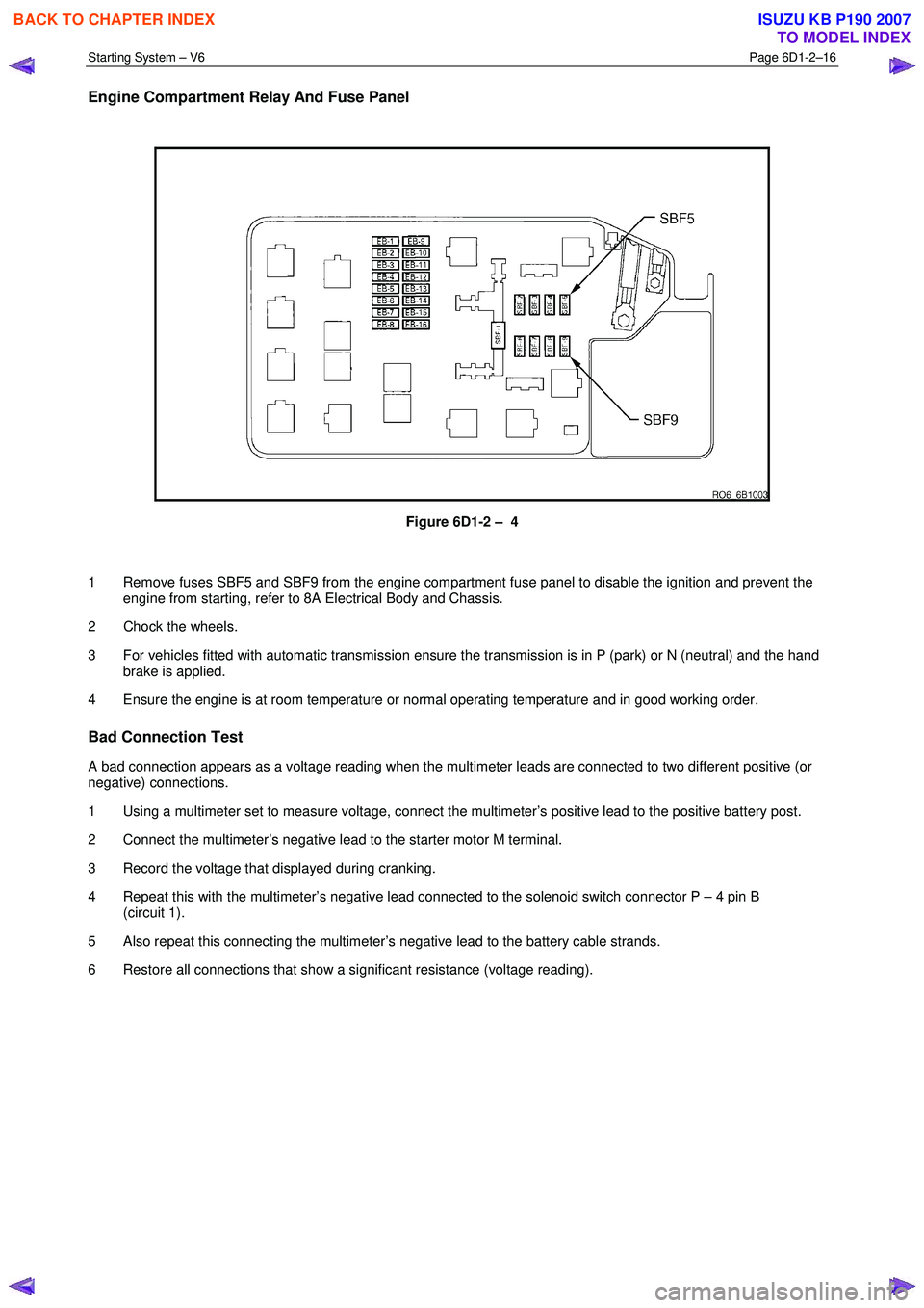
Figure 6D1-2 – 4
1 Remove fuses SBF5 and SBF9 from the engine compartment fuse panel to disable the ignition and prevent the engine from starting, refer to 8A Electrical Body and Chassis.
2 Chock the wheels.
3 For vehicles fitted with automatic transmission ensure the transmission is in P (park) or N (neutral) and the hand brake is applied.
4 Ensure the engine is at room temperature or normal operating temperature and in good working order.
Bad Connection Test
A bad connection appears as a voltage reading when the multimeter leads are connected to two different positive (or
negative) connections.
1 Using a multimeter set to measure voltage, connect the multimeter’s positive lead to the positive battery post.
2 Connect the multimeter’s negative lead to the starter motor M terminal.
3 Record the voltage that displayed during cranking.
4 Repeat this with the multimeter’s negative lead connected to the solenoid switch connector P – 4 pin B (circuit 1).
5 Also repeat this connecting the multimeter’s negative lead to the battery cable strands.
6 Restore all connections that show a significant resistance (voltage reading).
BACK TO CHAPTER INDEX
TO MODEL INDEX
ISUZU KB P190 2007
Page 3625 of 6020
Starting System – V6 Page 6D1-2–17
Starter Motor Ground Test
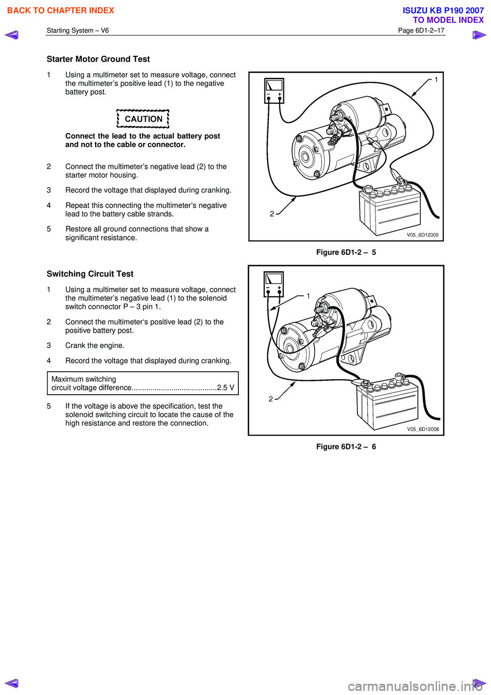
1 Using a multimeter set to measure voltage, connect
the multimeter’s positive lead (1) to the negative
battery post.
Connect the lead to the actual battery post
and not to the cable or connector.
2 Connect the multimeter’s negative lead (2) to the starter motor housing.
3 Record the voltage that displayed during cranking.
4 Repeat this connecting the multimeter’s negative lead to the battery cable strands.
5 Restore all ground connections that show a significant resistance.
Figure 6D1-2 – 5
Switching Circuit Test
1 Using a multimeter set to measure voltage, connect
the multimeter’s negative lead (1) to the solenoid
switch connector P – 3 pin 1.
2 Connect the multimeter‘s positive lead (2) to the positive battery post.
3 Crank the engine.
4 Record the voltage that displayed during cranking.
Maximum switching
circuit voltage difference.........................................2.5 V
5 If the voltage is above the specification, test the solenoid switching circuit to locate the cause of the
high resistance and restore the connection.
Figure 6D1-2 – 6
BACK TO CHAPTER INDEX
TO MODEL INDEX
ISUZU KB P190 2007