2007 ISUZU KB P190 ECO mode
[x] Cancel search: ECO modePage 3523 of 6020
Engine Management – V6 – Diagnostics Page 6C1-2–245
Starter Motor Relay Test
The engine will crank and start during the
starter relay test.
Allows the Technician to turn the starter relay ‘On’, thereby activating the starter motor and cranking the engine.
Preconditions: Apply park brake, firmly apply foot brake, ignition ‘On’, engine ‘Off’, transmission in Park or Neutral.
Fuel Injector Balance
This test allows the Technician to check the fuel flow through each injector when the engine is not running. The
sequence of events are:
1 Install a fuel pressure gauge to the fuel rail.
2 Select ‘Fuel Injector Balance Test’, from the ‘Actuator Test’ menu on Tech 2
3 Activate the fuel injector balance test with Tech 2. This action activates the fuel pump and stabilises the fuel delivery system fuel pressure. The fuel pump is then turned off.
4 Note the stabilised fuel rail pressure.
5 W hen the pump is turned ‘Off’, the injector is activated for a pre-determined time.
6 The fuel pressure drop is then noted from the fuel pressure gauge.
NOTE
For a detailed procedure and analysis of fuel
injector condition, refer to 5.3 Fuel Injector
Balance Test.
8.7 Programming
F0: ICU Link to ECM/PIM : Should the ECM, PIM or ICU be replaced, the modules must be security linked to
each other. If this linking procedure is not performed, the vehicle will not crank nor run. For additional
information relating to Tech 2 and the linking procedure, refer to 11A – Immobiliser.
NOTE
After an ECU reset, the ignition switch must be
turned Off for at least 10 seconds and then
turned On for at least one minute, before
attempting communication between Tech 2 and
the ECU.
Preconditions: TIS approval (TIS 2000 Security Access) must be obtained, the four digit security number
entered into Tech 2 and the theft deterrent system disarmed. Then the ignition must be turned ‘On’, using a
programmed remote coded key.
F1: Reset ECU : This function erases the security link between the Engine Control Module (ECM) and the
Powertrain Interface Modules (PIM). If this procedure is performed, the engine will not crank nor run. A ICU
Link to ECM/PIM procedure will need to be performed. For additional information relating to the ICU Link to
ECM/PIM procedure, refer to 11A – Immobiliser.
BACK TO CHAPTER INDEX
TO MODEL INDEX
ISUZU KB P190 2007
Page 3524 of 6020
Engine Management – V6 – Diagnostics Page 6C1-2–246
NOTE
After an ECU reset, the ignition switch must be
turned Off for at least 10 seconds and then
turned On for at least one minute, before
attempting communication between Tech 2 and
the ECU.
Preconditions: The four digit security code must be entered into Tech 2 and the theft deterrent system
must be disarmed and the ignition switched ‘On’ with a programmed remote coded key.
F2: Fuel Trim Reset : This function resets the fuel trim data values learned by the ECM.
F3: Throttle Body Relearn : In this mode, Tech 2 commands the throttle plate from its rest position to full closed
then to about 10% open. This procedure takes approximately 6 – 8 seconds. At the start of this procedure,
the Tech 2, ‘Electronic Throttle Control Learn Counter’ parameter should display ‘0’ then count up to 11, after
the procedure is completed. If the counter does not start at ‘0’, nor display a count of ‘11’ at the conclusion of
the procedure, a fault has occurred and a DTC will set.
BACK TO CHAPTER INDEX
TO MODEL INDEX
ISUZU KB P190 2007
Page 3528 of 6020
Engine Management – V6 – Service Operations Page 6C1-3–4
1 General Information
1.1 General Description
This Section describes the correct service procedures to repair and test components of the V6 engine management
system. Emphasis is placed on the proper procedures and repair of components related to this specific system.
For component description, operation and location, refer to 6C1-1 Engine Management – V6 – General Information.
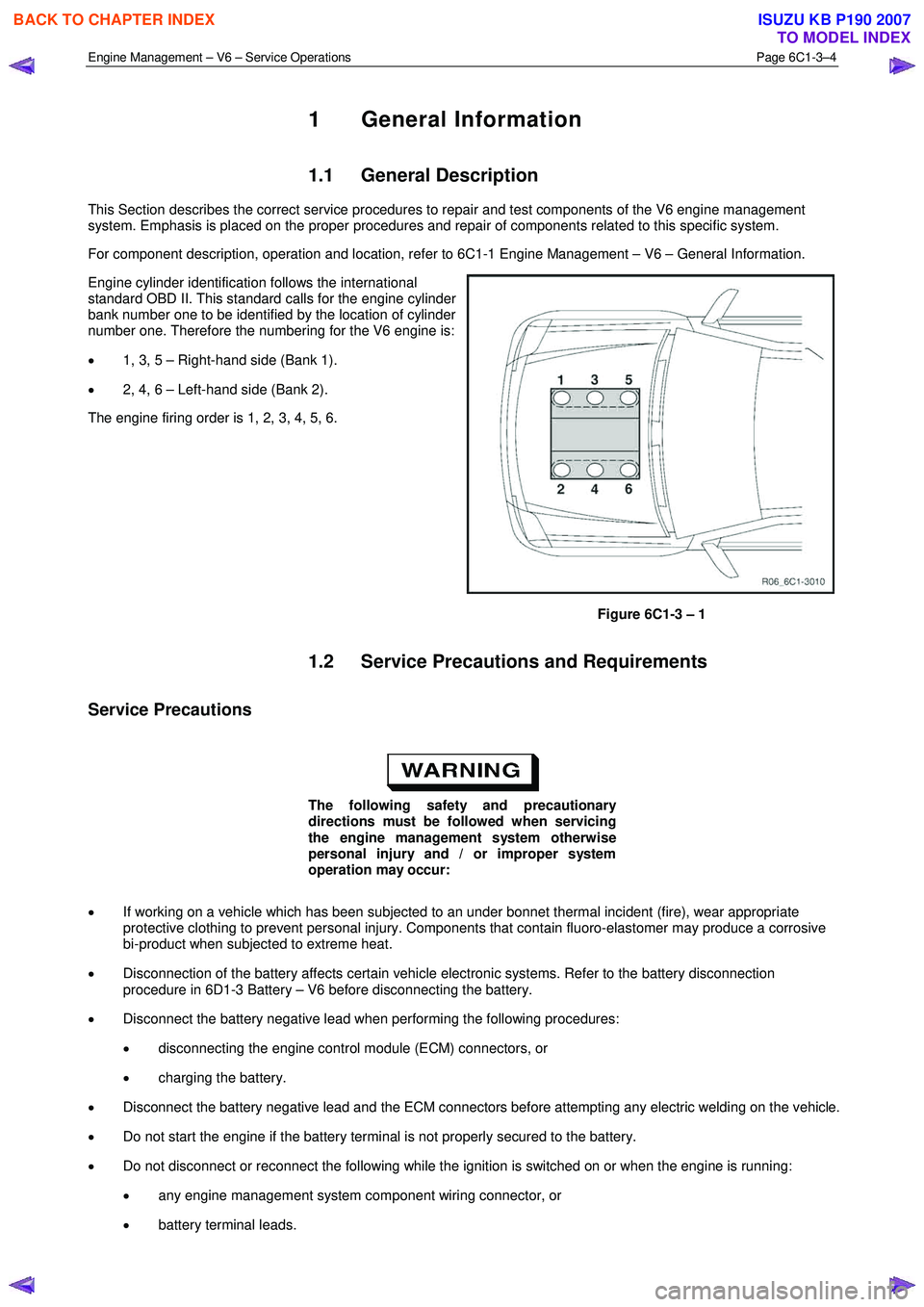
Engine cylinder identification follows the international
standard OBD II. This standard calls for the engine cylinder
bank number one to be identified by the location of cylinder
number one. Therefore the numbering for the V6 engine is:
• 1, 3, 5 – Right-hand side (Bank 1).
• 2, 4, 6 – Left-hand side (Bank 2).
The engine firing order is 1, 2, 3, 4, 5, 6.
Figure 6C1-3 – 1
1.2 Service Precautions and Requirements
Service Precautions
The following safety and precautionary
directions must be followed when servicing
the engine management system otherwise
personal injury and / or improper system
operation may occur:
• If working on a vehicle which has been subjected to an under bonnet thermal incident (fire), wear appropriate
protective clothing to prevent personal injury. Components that contain fluoro-elastomer may produce a corrosive
bi-product when subjected to extreme heat.
• Disconnection of the battery affects certain vehicle electronic systems. Refer to the battery disconnection
procedure in 6D1-3 Battery – V6 before disconnecting the battery.
• Disconnect the battery negative lead when performing the following procedures:
• disconnecting the engine control module (ECM) connectors, or
• charging the battery.
• Disconnect the battery negative lead and the ECM connectors before attempting any electric welding on the vehicle.
• Do not start the engine if the battery terminal is not properly secured to the battery.
• Do not disconnect or reconnect the following while the ignition is switched on or when the engine is running:
• any engine management system component wiring connector, or
• battery terminal leads.
BACK TO CHAPTER INDEX
TO MODEL INDEX
ISUZU KB P190 2007
Page 3529 of 6020
Engine Management – V6 – Service Operations Page 6C1-3–5
• Ensure the correct procedure for disconnecting and connecting engine management system wiring connectors is
always followed.
• Ensure that all wiring connectors are fitted correctly.
• The engine management system wiring connectors are designed to fit only one way; there are indexing tabs and
slots on both halves of the connector. Forcing the connector into place is not necessary if it is being installed with
the correct orientation. Failure to take care to match the indexing tabs and slots correctly can cause damage to the
connector, the module, or other vehicle components or systems.
• Never touch the connector pins of any electronic component, such as an ECM, as electrostatic discharge (ESD)
damage may result.
• W hen steam or pressure cleaning engines, do not direct the cleaning nozzle at engine management system
components.
• Never subject the ECM to temperatures less than -40 ° C and greater than 125 ° C.
• Prior to disconnection or removal of any components associated with the fuel system, clean the area around any
connection points to avoid possible contamination of the fuel system.
• A depressurised fuel system contains fuel in the fuel system and fuel lines that can be spilled during service
operations. To reduce the chance of personal injury, cover the fittings with a shop towel to absorb any fuel spillage
prior to performing the service operation. Once the service operation has been completed, place the towel in an
approved container for disposal.
• To avoid accidental fuel discharge, it is advisable to disconnect the battery and remove the fuel pump relay if the
fuel line between the fuel pump and the fuel rail is to be disconnected / open for an indefinite period.
• Always tighten fasteners to the correct tightening torque, and where indicated in the service procedure, follow the
correct tightening sequence, precautions and recommendations to prevent premature failure of the fastener or
component.
• After removing components, such as the upper or lower intake manifold, front engine pipe, heated oxygen sensor,
etc. always plug any openings to prevent dirt and other contaminants from entering.
• Do not use silicone based assembly lubricants as damage to the heated oxygen sensors may result.
Use of incorrect electrical test equipment
when performing engine management service
procedures could result in incorrect results or
component damage.
• Use only the test equipment specified in the diagnostic tables. Use of other test equipment may either give
incorrect results or damage serviceable components, refer to, 6C1-2 Engine Management – V6 – Diagnostics.
• After completing the required service operations, road test the vehicle to ensure correct engine management
system operation.
Service Requirements
Basic Knowledge Required
A lack of basic understanding of electronics,
electrical wiring circuits and use of electrical
circuit testing tools when performing certain
service procedures could result in incorrect
results or damage to components.
In addition, a general understanding of the engine management system and its component operation is essential to
prevent misdiagnosis and component damage.
BACK TO CHAPTER INDEX
TO MODEL INDEX
ISUZU KB P190 2007
Page 3531 of 6020
Engine Management – V6 – Service Operations Page 6C1-3–7
Transmission – Automatic
For automatic transmission sensors and components, refer to 7C4 Automatic Transmission – 4L60E – On-vehicle
Servicing.
Transmission – Manual
For manual transmission sensors and other components, refer to 7B1 Manual Transmission – V6.
1.4 Warning Caution and Notes
This Section contains various W ARNINGS, CAUTIONS and NOTE statements that you must observe carefully to reduce
the risk of death or injury during service, repair procedures or vehicle operation. Incorrect service or repair procedures
may damage the vehicle or cause operational faults. W ARNINGS, CAUTION and NOTE statements are not exhaustive.
GM Holden LTD can not possibly warn of all the potentially hazardous consequences of failure to follow these
instructions.
Definition of WARNING, CAUTION and NOTE Statements
Diagnosis and repair procedures in this Section contain both general and specific W ARNING, CAUTION and NOTE
statements. GM Holden LTD is dedicated to the presentation of service information that helps the technician to diagnose
and repair the systems necessary for proper operation of the vehicle. Certain procedures may present a hazard to the
technician if they are not followed in the recommended manner. W ARNING, CAUTION and NOTE statements are
designed to help prevent these hazards from occurring, but not all hazards can be foreseen.
WARNING defined
A W ARNING statement immediately precedes an operating procedure or maintenance practice which, if not correctly
followed, could result in death or injury. A W ARNING statement alerts you to take necessary action or not to take a
prohibited action. If a W ARNING statement is ignored, the following consequences may occur:
• Death or injury to the technician or other personnel working on the vehicle,
• Death or injury to other people in or near the workplace area, and / or
• Death or injury to the driver / or passenger(s) of the vehicle or other people, if the vehicle has been improperly
repaired.
CAUTION defined
A CAUTION statement immediately precedes an operating procedure or maintenance practice which, if not correctly
followed, could result in damage to or destruction of equipment, or corruption of data. If a CAUTION statement is ignored,
the following consequences may occur:
• Damage to the vehicle,
• Unnecessary vehicle repairs or component replacement,
• Faulty operation or performance of any system or component being repaired,
• Damage to any system or components which depend on the proper operation of the system or component being
repaired,
• Faulty operation or performance of any systems or components which depend on the proper operation or
performance of the system or component under repair,
• Damage to fasteners, basic tools or special tools and / or
• Leakage of coolant, lubricant or other vital fluids.
NOTE defined
A NOTE statement immediately precedes or follows an operating procedure, maintenance practice or condition that
requires highlighting. A NOTE statement also emphasises necessary characteristics of a diagnostic or repair procedure.
A NOTE statement is designed to:
• Clarify a procedure,
• Present additional information for accomplishing a procedure,
BACK TO CHAPTER INDEX
TO MODEL INDEX
ISUZU KB P190 2007
Page 3532 of 6020

Engine Management – V6 – Service Operations Page 6C1-3–8
• Give insight into the reasons for performing a procedure in the recommended manner, and / or
• Present information that gives the technician the benefit of past experience in accomplishing a procedure with
greater ease.
BACK TO CHAPTER INDEX
TO MODEL INDEX
ISUZU KB P190 2007
Page 3544 of 6020
Engine Management – V6 – Service Operations Page 6C1-3–20
Reinstall
Reinstallation of the engine control module (ECM) is the reverse of the removal procedure, noting the following:
NOTE
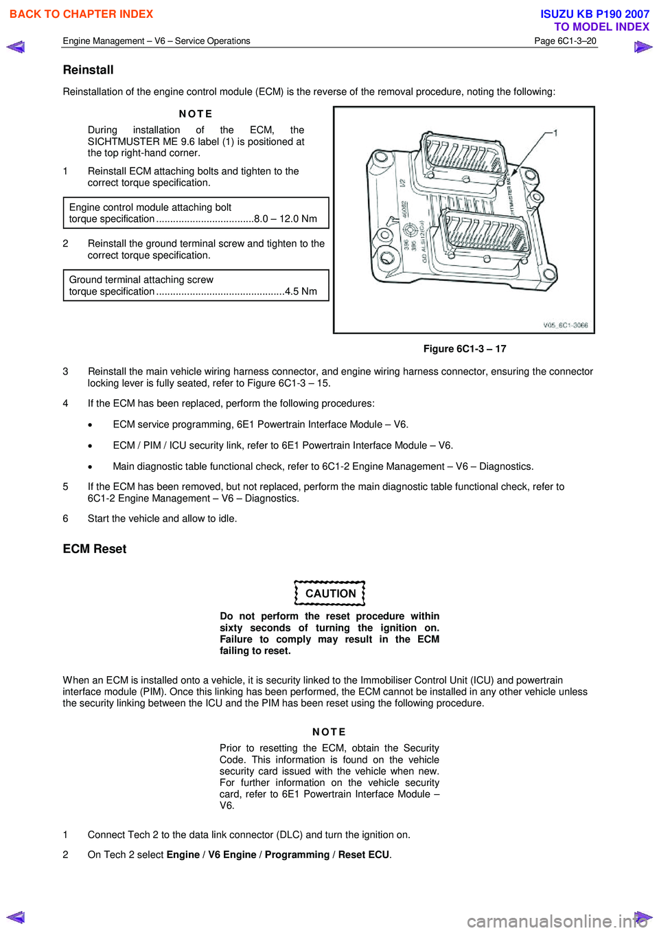
During installation of the ECM, the
SICHTMUSTER ME 9.6 label (1) is positioned at
the top right-hand corner.
1 Reinstall ECM attaching bolts and tighten to the correct torque specification.
Engine control module attaching bolt
torque specification ...................................8.0 – 12.0 Nm
2 Reinstall the ground terminal screw and tighten to the correct torque specification.
Ground terminal attaching screw
torque specification ..............................................4.5 Nm
Figure 6C1-3 – 17
3 Reinstall the main vehicle wiring harness connector, and engine wiring harness connector, ensuring the connector locking lever is fully seated, refer to Figure 6C1-3 – 15.
4 If the ECM has been replaced, perform the following procedures:
• ECM service programming, 6E1 Powertrain Interface Module – V6.
• ECM / PIM / ICU security link, refer to 6E1 Powertrain Interface Module – V6.
• Main diagnostic table functional check, refer to 6C1-2 Engine Management – V6 – Diagnostics.
5 If the ECM has been removed, but not replaced, perform the main diagnostic table functional check, refer to 6C1-2 Engine Management – V6 – Diagnostics.
6 Start the vehicle and allow to idle.
ECM Reset
Do not perform the reset procedure within
sixty seconds of turning the ignition on.
Failure to comply may result in the ECM
failing to reset.
W hen an ECM is installed onto a vehicle, it is security linked to the Immobiliser Control Unit (ICU) and powertrain
interface module (PIM). Once this linking has been performed, the ECM cannot be installed in any other vehicle unless
the security linking between the ICU and the PIM has been reset using the following procedure.
NOTE
Prior to resetting the ECM, obtain the Security
Code. This information is found on the vehicle
security card issued with the vehicle when new.
For further information on the vehicle security
card, refer to 6E1 Powertrain Interface Module –
V6.
1 Connect Tech 2 to the data link connector (DLC) and turn the ignition on.
2 On Tech 2 select Engine / V6 Engine / Programming / Reset ECU .
BACK TO CHAPTER INDEX
TO MODEL INDEX
ISUZU KB P190 2007
Page 3552 of 6020
Engine Management – V6 – Service Operations Page 6C1-3–28
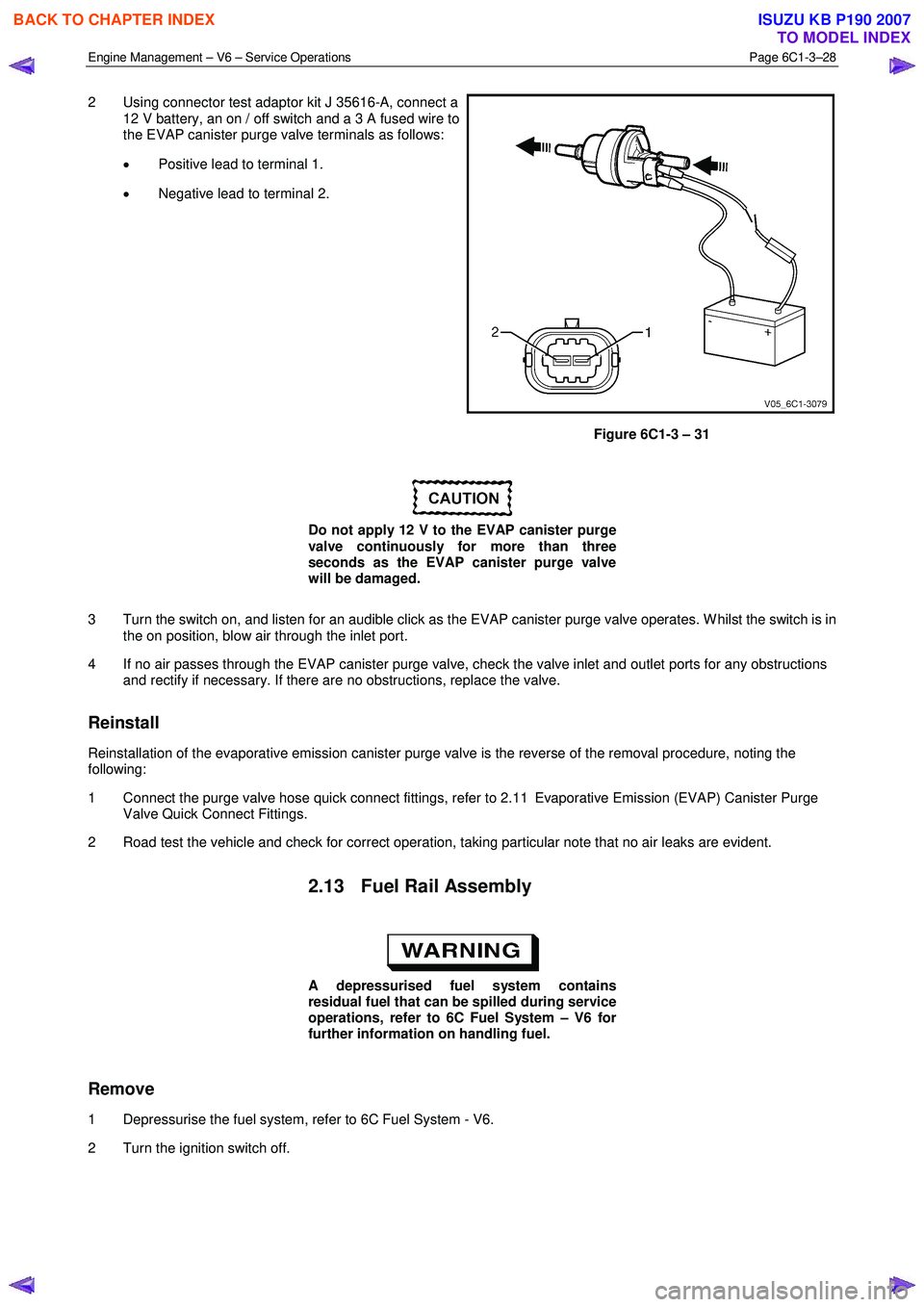
2 Using connector test adaptor kit J 35616-A, connect a
12 V battery, an on / off switch and a 3 A fused wire to
the EVAP canister purge valve terminals as follows:
• Positive lead to terminal 1.
• Negative lead to terminal 2.
Figure 6C1-3 – 31
Do not apply 12 V to the EVAP canister purge
valve continuously for more than three
seconds as the EVAP canister purge valve
will be damaged.
3 Turn the switch on, and listen for an audible click as the EVAP canister purge valve operates. W hilst the switch is in the on position, blow air through the inlet port.
4 If no air passes through the EVAP canister purge valve, check the valve inlet and outlet ports for any obstructions and rectify if necessary. If there are no obstructions, replace the valve.
Reinstall
Reinstallation of the evaporative emission canister purge valve is the reverse of the removal procedure, noting the
following:
1 Connect the purge valve hose quick connect fittings, refer to 2.11 Evaporative Emission (EVAP) Canister Purge Valve Quick Connect Fittings.
2 Road test the vehicle and check for correct operation, taking particular note that no air leaks are evident.
2.13 Fuel Rail Assembly
A depressurised fuel system contains
residual fuel that can be spilled during service
operations, refer to 6C Fuel System – V6 for
further information on handling fuel.
Remove
1 Depressurise the fuel system, refer to 6C Fuel System - V6.
2 Turn the ignition switch off.
BACK TO CHAPTER INDEX
TO MODEL INDEX
ISUZU KB P190 2007