2007 ISUZU KB P190 ECO mode
[x] Cancel search: ECO modePage 3557 of 6020
Engine Management – V6 – Service Operations Page 6C1-3–33
Reinstall
Reinstallation of the fuel injector wiring harness assembly is the reverse of the removal procedure, noting the following:
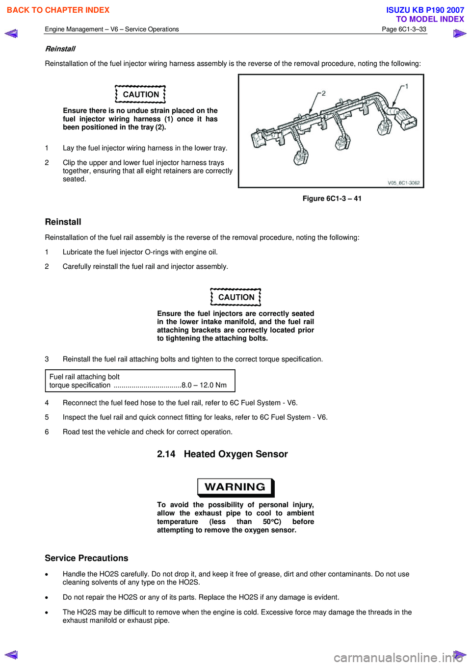
Ensure there is no undue strain placed on the
fuel injector wiring harness (1) once it has
been positioned in the tray (2).
1 Lay the fuel injector wiring harness in the lower tray.
2 Clip the upper and lower fuel injector harness trays together, ensuring that all eight retainers are correctly
seated.
Figure 6C1-3 – 41
Reinstall
Reinstallation of the fuel rail assembly is the reverse of the removal procedure, noting the following:
1 Lubricate the fuel injector O-rings with engine oil.
2 Carefully reinstall the fuel rail and injector assembly.
Ensure the fuel injectors are correctly seated
in the lower intake manifold, and the fuel rail
attaching brackets are correctly located prior
to tightening the attaching bolts.
3 Reinstall the fuel rail attaching bolts and tighten to the correct torque specification. Fuel rail attaching bolt
torque specification ..................................8.0 – 12.0 Nm
4 Reconnect the fuel feed hose to the fuel rail, refer to 6C Fuel System - V6.
5 Inspect the fuel rail and quick connect fitting for leaks, refer to 6C Fuel System - V6.
6 Road test the vehicle and check for correct operation.
2.14 Heated Oxygen Sensor
To avoid the possibility of personal injury,
allow the exhaust pipe to cool to ambient
temperature (less than 50 °
°°
°
C) before
attempting to remove the oxygen sensor.
Service Precautions
• Handle the HO2S carefully. Do not drop it, and keep it free of grease, dirt and other contaminants. Do not use
cleaning solvents of any type on the HO2S.
• Do not repair the HO2S or any of its parts. Replace the HO2S if any damage is evident.
• The HO2S may be difficult to remove when the engine is cold. Excessive force may damage the threads in the
exhaust manifold or exhaust pipe.
BACK TO CHAPTER INDEX
TO MODEL INDEX
ISUZU KB P190 2007
Page 3563 of 6020
Engine Management – V6 – Service Operations Page 6C1-3–39
Disassemble
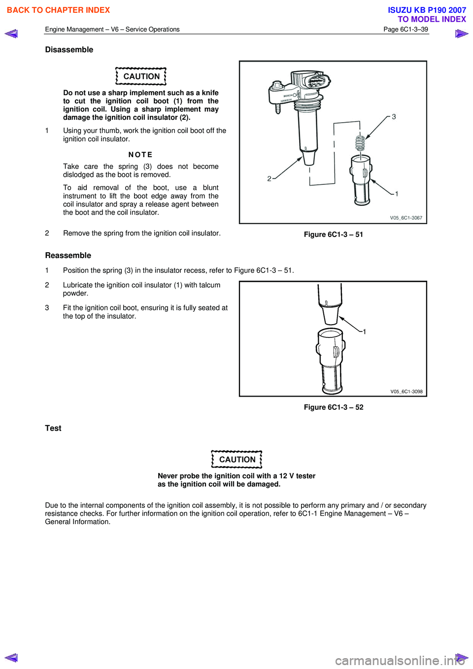
Do not use a sharp implement such as a knife
to cut the ignition coil boot (1) from the
ignition coil. Using a sharp implement may
damage the ignition coil insulator (2).
1 Using your thumb, work the ignition coil boot off the ignition coil insulator.
NOTE
Take care the spring (3) does not become
dislodged as the boot is removed.
To aid removal of the boot, use a blunt
instrument to lift the boot edge away from the
coil insulator and spray a release agent between
the boot and the coil insulator.
2 Remove the spring from the ignition coil insulator.
Figure 6C1-3 – 51
Reassemble
1 Position the spring (3) in the insulator recess, refer to Figure 6C1-3 – 51.
2 Lubricate the ignition coil insulator (1) with talcum powder.
3 Fit the ignition coil boot, ensuring it is fully seated at the top of the insulator.
Figure 6C1-3 – 52
Test
Never probe the ignition coil with a 12 V tester
as the ignition coil will be damaged.
Due to the internal components of the ignition coil assembly, it is not possible to perform any primary and / or secondary
resistance checks. For further information on the ignition coil operation, refer to 6C1-1 Engine Management – V6 –
General Information.
BACK TO CHAPTER INDEX
TO MODEL INDEX
ISUZU KB P190 2007
Page 3569 of 6020

Engine Management – V6 – Service Operations Page 6C1-3–45
Ensure the knock sensor is fully seated
before tightening the attaching bolt.
Do not over-tighten the attaching bolt as
incorrect operation of the knock sensor may
result.
2 Reinstall the knock sensor and bolt (1). Align the knock sensor so that it is parallel to the engine oil pan
mounting surface (2), ± 3° (3).
3 Tighten the knock sensor bolt to the correct torque specification.
Knock sensor attaching bolt
torque specification .................................21.0 – 25.0 Nm
4 Road test the vehicle and check for correct operation.
Figure 6C1-3 – 61
2.20 Mass Air Flow Sensor
The intake air temperature (IAT) sensor is part of the mass air flow (MAF) Sensor. For the IAT sensor test procedure
refer to 2.17 Intake Air Temperature Sensor.
Handling Precautions
Under no circumstances should the MAF
sensor retaining screws (1) be loosened or
removed as the MAF will become
unserviceable and will require replacement.
Figure 6C1-3 – 62
Remove
1 Turn the ignition switch off.
BACK TO CHAPTER INDEX
TO MODEL INDEX
ISUZU KB P190 2007
Page 3573 of 6020
Engine Management – V6 – Service Operations Page 6C1-3–49
1 Replace any plug that has cracked and / or broken insulation or loose electrodes.
2 Inspect the spark plugs for defects. Refer to Analysis of Spark Plug Condition in this Section for identification of the condition of spark plugs.
3 Ensure the threads are clean and in good order.
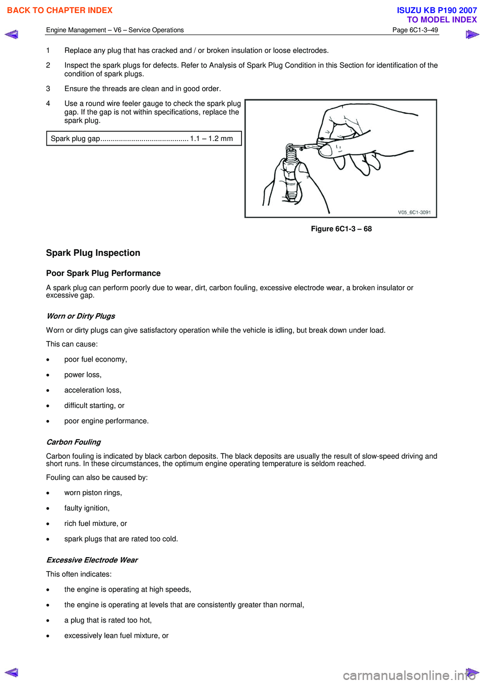
4 Use a round wire feeler gauge to check the spark plug gap. If the gap is not within specifications, replace the
spark plug.
Spark plug gap ........................................... 1.1 – 1.2 mm
Figure 6C1-3 – 68
Spark Plug Inspection
Poor Spark Plug Performance
A spark plug can perform poorly due to wear, dirt, carbon fouling, excessive electrode wear, a broken insulator or
excessive gap.
Worn or Dirty Plugs
W orn or dirty plugs can give satisfactory operation while the vehicle is idling, but break down under load.
This can cause:
• poor fuel economy,
• power loss,
• acceleration loss,
• difficult starting, or
• poor engine performance.
Carbon Fouling
Carbon fouling is indicated by black carbon deposits. The black deposits are usually the result of slow-speed driving and
short runs. In these circumstances, the optimum engine operating temperature is seldom reached.
Fouling can also be caused by:
• worn piston rings,
• faulty ignition,
• rich fuel mixture, or
• spark plugs that are rated too cold.
Excessive Electrode Wear
This often indicates:
• the engine is operating at high speeds,
• the engine is operating at levels that are consistently greater than normal,
• a plug that is rated too hot,
• excessively lean fuel mixture, or
BACK TO CHAPTER INDEX
TO MODEL INDEX
ISUZU KB P190 2007
Page 3579 of 6020
Engine Management – V6 – Service Operations Page 6C1-3–55
Inspect
The following throttle body inspection procedure may be carried out with the throttle body installed on the vehicle. Prior to
performing a throttle body on-vehicle inspection:
• Turn the ignition switch off.
• Disconnect the throttle body wiring harness connector. Refer to Remove in this Section.
• Remove the air intake duct, refer to 2.16 Intake Air Duct Assembly.
To avoid serious personal injury, never
attempt to rotate the throttle plate manually
whilst the throttle body harness connector is
connected to the throttle body.
1 Fully open the throttle plate by hand and inspect the throttle body bore and throttle plate for any deposits.
When cleaning / inspecting the throttle body:
• Do not subject the throttle body assembly
to an immersion cleaner or a strong
solvent. Damage to the throttle position
sensor and / or sealed throttle shaft
bearings will result.
• Never use a wire brush or scraper to clean
the throttle body. A wire brush or sharp
tool may damage the throttle body
components.
2 Use a clean shop towel and a spray type hydro-carbon cleaner to clean the throttle body bore and throttle plate. If necessary, use a parts cleaning brush to remove heavy deposits.
3 Inspect the throttle body for a binding throttle plate by fully opening and closing the throttle plate by hand. It should open and close smoothly.
4 Inspect the throttle body for a bent or damaged throttle plate, cracks, corrosion, or distortion in the throttle body housing.
NOTE
The throttle body contains no serviceable parts
and should not be disassembled. If the throttle
body is damaged it must be replaced as an
assembly.
5 If the throttle body is affected by any of the above conditions, it must be replaced.
6 If an on-vehicle throttle body inspection was performed, perform the following:
• Reinstall the air intake duct, refer to 2.16 Intake Air Duct Assembly.
• Reconnect the throttle body wiring harness connector, refer to Reinstall in this Section.
• Road test the vehicle and check for correct operation, taking particular note that no air leaks are evident.
Reinstall
Reinstallation of the throttle body assembly is the reverse of the removal procedure, noting the following:
1 Ensure the throttle body and upper intake manifold mating surfaces are clean and free of foreign material.
2 Install a new throttle body to upper intake manifold gasket.
BACK TO CHAPTER INDEX
TO MODEL INDEX
ISUZU KB P190 2007
Page 3591 of 6020
Charging System – V6 Page 6D1-1-4
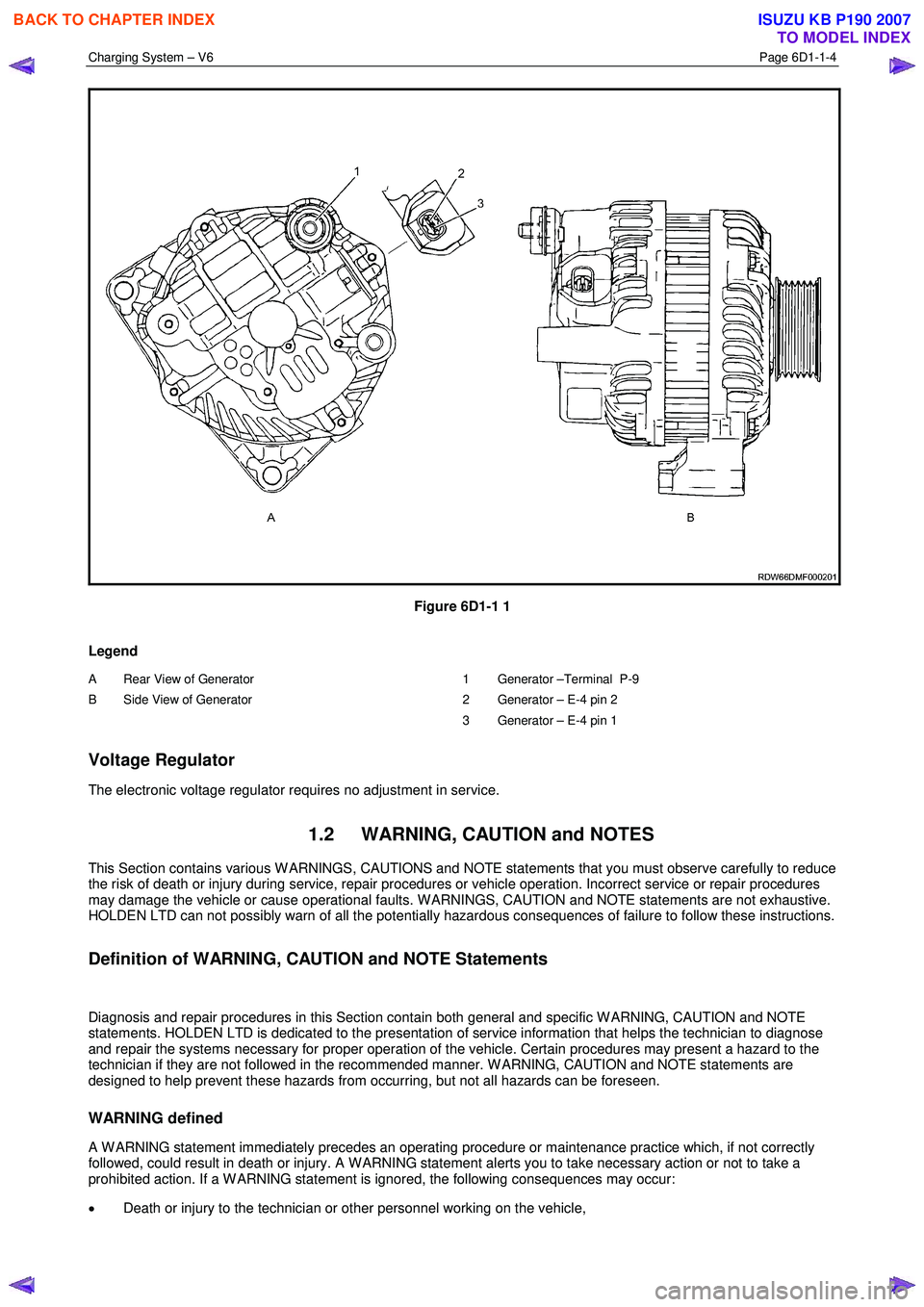
Figure 6D1-1 1
Legend
A Rear View of Generator
B Side View of Generator
1 Generator –Terminal P-9
2 Generator – E-4 pin 2
3 Generator – E-4 pin 1
Voltage Regulator
The electronic voltage regulator requires no adjustment in service.
1.2 WARNING, CAUTION and NOTES
This Section contains various W ARNINGS, CAUTIONS and NOTE statements that you must observe carefully to reduce
the risk of death or injury during service, repair procedures or vehicle operation. Incorrect service or repair procedures
may damage the vehicle or cause operational faults. W ARNINGS, CAUTION and NOTE statements are not exhaustive.
HOLDEN LTD can not possibly warn of all the potentially hazardous consequences of failure to follow these instructions.
Definition of WARNING, CAUTION and NOTE Statements
Diagnosis and repair procedures in this Section contain both general and specific W ARNING, CAUTION and NOTE
statements. HOLDEN LTD is dedicated to the presentation of service information that helps the technician to diagnose
and repair the systems necessary for proper operation of the vehicle. Certain procedures may present a hazard to the
technician if they are not followed in the recommended manner. W ARNING, CAUTION and NOTE statements are
designed to help prevent these hazards from occurring, but not all hazards can be foreseen.
WARNING defined
A W ARNING statement immediately precedes an operating procedure or maintenance practice which, if not correctly
followed, could result in death or injury. A W ARNING statement alerts you to take necessary action or not to take a
prohibited action. If a W ARNING statement is ignored, the following consequences may occur:
• Death or injury to the technician or other personnel working on the vehicle,
BACK TO CHAPTER INDEX
TO MODEL INDEX
ISUZU KB P190 2007
Page 3592 of 6020
Charging System – V6 Page 6D1-1-5
• Death or injury to other people in or near the workplace area, and / or
• Death or injury to the driver / or passenger(s) of the vehicle or other people, if the vehicle has been improperly
repaired.
CAUTION defined
A CAUTION statement immediately precedes an operating procedure or maintenance practice which, if not correctly
followed, could result in damage to or destruction of equipment, or corruption of data. If a CAUTION statement is
ignored, the following consequences may occur:
• Damage to the vehicle,
• Unnecessary vehicle repairs or component replacement,
• Faulty operation or performance of any system or component being repaired,
• Damage to any system or components which depend on the proper operation of the system or component being
repaired,
• Faulty operation or performance of any systems or components which depend on the proper operation or
performance of the system or component under repair,
• Damage to fasteners, basic tools or special tools and / or
• Leakage of coolant, lubricant or other vital fluids.
NOTE defined
A NOTE statement immediately precedes or follows an operating procedure, maintenance practice or condition that
requires highlighting. A NOTE statement also emphasises necessary characteristics of a diagnostic or repair procedure.
A NOTE statement is designed to:
• Clarify a procedure,
• Present additional information for accomplishing a procedure,
• Give insight into the reasons for performing a procedure in the recommended manner, and / or
• Present information that gives the technician the benefit of past experience in accomplishing a procedure with
greater ease.
1.3 System Operation
Operation
W ith the ignition switch in the ON position and the engine at rest, current is supplied via the regulator to generator
connector E-4 pin 1 and to the engine control module ECM connector E-60 pin 43. This initiates current flow (within the
regulator) from the generator connection P-9, to the brushes and rotor winding, to ‘excite’ the circuit.
The current in the rotor winding creates magnetic fields between adjacent rotor poles.
W ith the engine running, the rotor spins, the stator windings cut through this field and induce voltage. As the engine
speed is increased, this induced voltage increases. Current then flows through the three-phase diode bridge in the
rectifier to convert the AC voltage to DC. This is supplied to the generator connector P-9 output and then to the battery
terminal via fuse SBF1.
The regulator monitors the voltage to the battery. W hen this voltage reaches approximately 14.5 V, the regulator opens
the circuit through the rotor winding, causing the generator output voltage to drop. W hen the regulator senses a voltage
below a preset voltage, the regulator closes the circuit through the rotor winding and voltage to the battery again
increases. This cycle repeats very rapidly.
BACK TO CHAPTER INDEX
TO MODEL INDEX
ISUZU KB P190 2007
Page 3598 of 6020
Charging System – V6 Page 6D1-1-11
3.3 On-vehicle Testing
Generator On-vehicle Checks
Prerequisites
Before testing the generator output, ensure that:
• all generator circuit connections are clean and tight,
• the generator is always connected to the battery during testing (to prevent damage to the diodes),
• the battery is fully charged, and
• the specific gravity does not vary more than 0.025 between cells. (It is recommended the average specific gravity
is 1.260 or higher). Refer to 6D1-3 Battery – V6.
Carry out a load test on the battery to determine its ability to supply and accept current. This is a good indicator of the
general condition of the battery. For details of battery testing, refer to 6D1-3 Battery – V6.
Inspect the drive belt and tensioner markings to determine if the drive belt is within operating limits. Replace the belt if it
is excessively worn or outside the operating range of the tensioner.
For further details, refer to 6A1 Engine Mechanical – V6.
Generator Test
Regulating Voltage Test
NOTE
Leave the generator E-4 wiring harness
connector connected, as it provides initial field
excitation.
1 Ensure the ignition switch is in the OFF position and all electrical equipment is turned off.
Refer to 1.2 WARNING, CAUTION and
NOTES before disconnecting the battery.
2 Disconnect the battery ground cable P-5 at the battery.
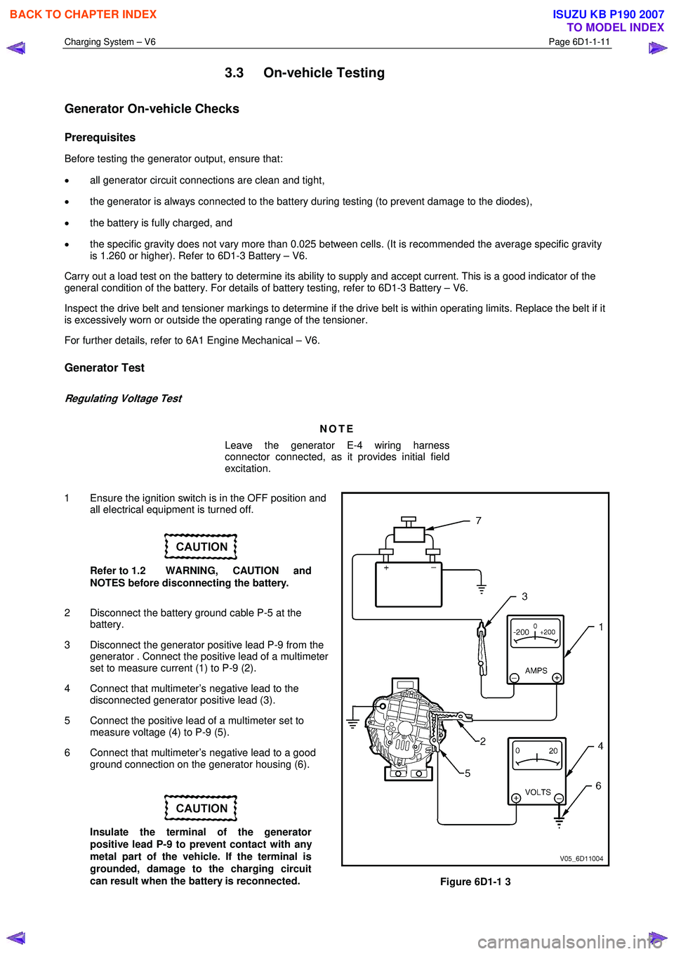
3 Disconnect the generator positive lead P-9 from the generator . Connect the positive lead of a multimeter
set to measure current (1) to P-9 (2).
4 Connect that multimeter’s negative lead to the disconnected generator positive lead (3).
5 Connect the positive lead of a multimeter set to measure voltage (4) to P-9 (5).
6 Connect that multimeter’s negative lead to a good ground connection on the generator housing (6).
Insulate the terminal of the generator
positive lead P-9 to prevent contact with any
metal part of the vehicle. If the terminal is
grounded, damage to the charging circuit
can result when the battery is reconnected.
Figure 6D1-1 3
BACK TO CHAPTER INDEX
TO MODEL INDEX
ISUZU KB P190 2007