2007 ISUZU KB P190 ECO mode
[x] Cancel search: ECO modePage 3647 of 6020
Battery Page 6D1-3–7
3 Diagnosis
3.1 Diagnostic Procedures
Introduction
This test is used to aid in diagnosing faults with the vehicle where the battery seems to be at fault.
W ith the increased use of electronic sensors and computer control, the battery is much more than just a component used
to start a car. Low battery voltage can:
• affect the operation of the vehicle control modules and cause driveability problems, and
• cause the control modules to set diagnostic trouble codes (DTCs).
For example if a control module senses low battery voltage, it may increase fuel injector timing to increase engine rpm to
increase the generator output.
Therefore consider the state of charge of the battery any time a customer complains of a driveability related problem.
Test Description
The following numbers refer to the step numbers in the diagnostic table:
1 Checks the operator understands the safety precautions for working with batteries.
2 Checks if the vehicle is fitted with a battery of the correct specification.
3 Checks if the battery appears serviceable by performing the battery inspection procedure.
4 Checks if the battery loses charge over an extended period. If so the likely problem is excess current draw while the vehicles ignition is in the off position.
5 Checks the state of charge of the battery.
6 Checks if the battery is capable of delivering the required load by performing the load test procedure.
Diagnostic Table Notes
1 For all wiring harness fault diagnosis, refer to 8A Electrical Body & Chassis.
2 For wiring harness repairs, refer to 8A Electrical Body & Chassis.
3 Refer to 6D1 – 3 Battery – V6.
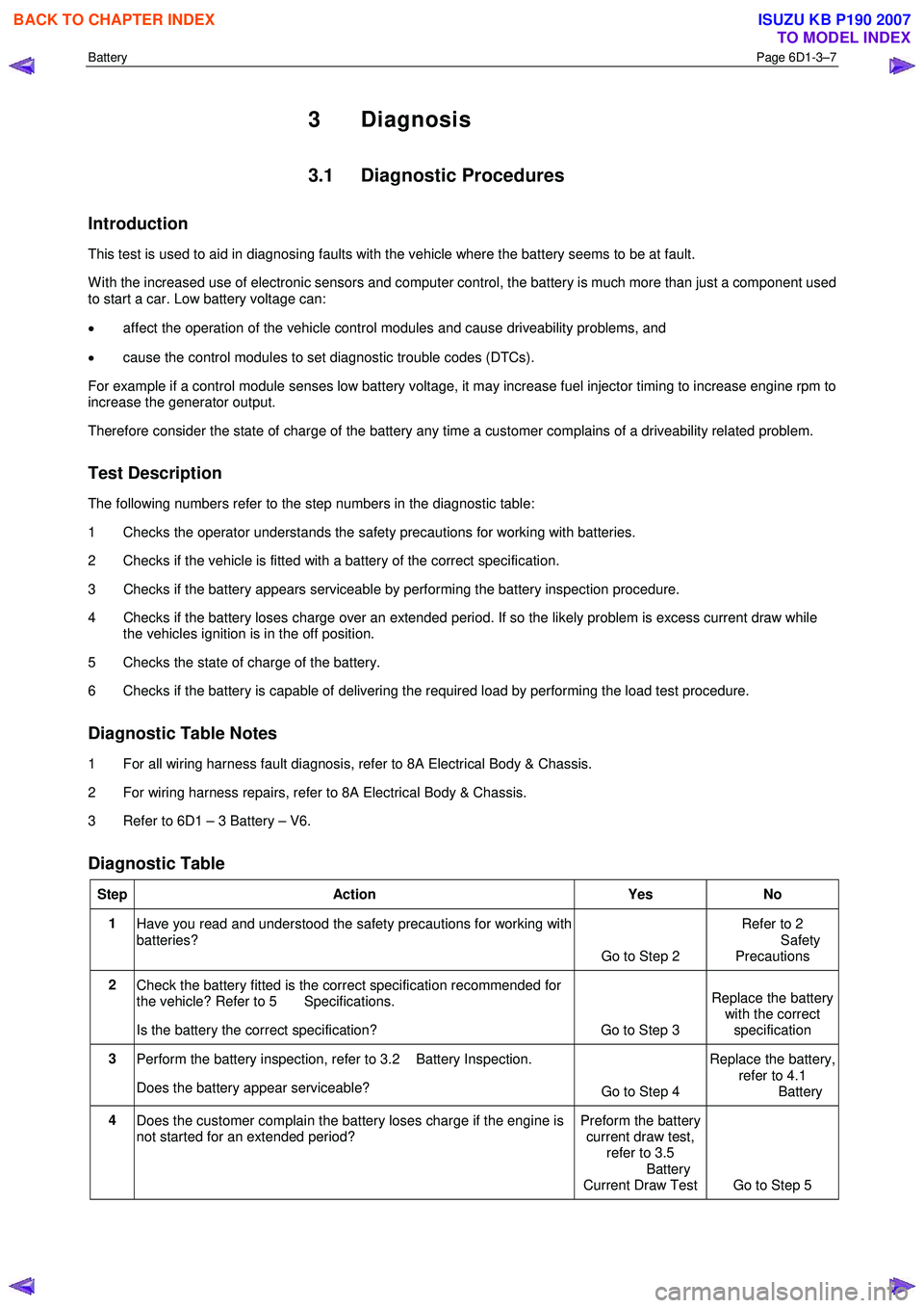
Diagnostic Table
Step Action Yes No
1
Have you read and understood the safety precautions for working with
batteries? Go to Step 2 Refer to 2
Safety Precautions
2 Check the battery fitted is the correct specification recommended for
the vehicle? Refer to 5 Specifications.
Is the battery the correct specification? Go to Step 3 Replace the battery
with the correct
specification
3 Perform the battery inspection, refer to 3.2 Battery Inspection.
Does the battery appear serviceable? Go to Step 4 Replace the battery,
refer to 4.1
Battery
4 Does the customer complain the battery loses charge if the engine is
not started for an extended period? Preform the battery
current draw test, refer to 3.5
Battery
Current Draw Test Go to Step 5
BACK TO CHAPTER INDEX
TO MODEL INDEX
ISUZU KB P190 2007
Page 3650 of 6020
Battery Page 6D1-3–10
6 Still holding the hydrometer vertically, record the reading.
7 Put the electrolyte back into the cell.
8 Repeat steps 3 to 7 for each cell.
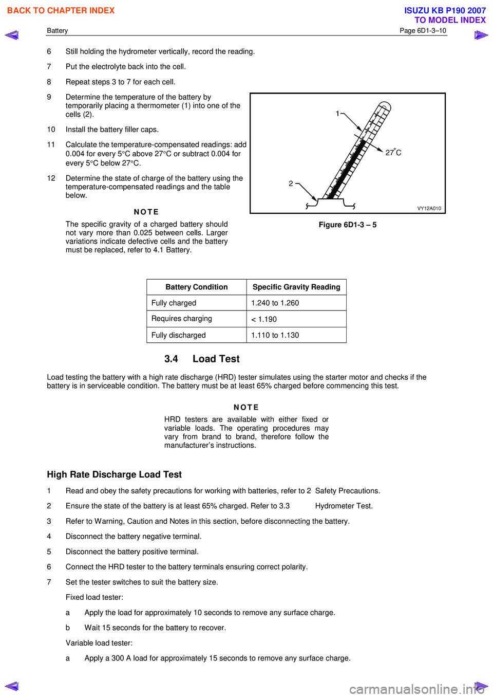
9 Determine the temperature of the battery by temporarily placing a thermometer (1) into one of the
cells (2).
10 Install the battery filler caps.
11 Calculate the temperature-compensated readings: add 0.004 for every 5 °C above 27 °C or subtract 0.004 for
every 5 °C below 27 °C.
12 Determine the state of charge of the battery using the temperature-compensated readings and the table
below.
NOTE
The specific gravity of a charged battery should
not vary more than 0.025 between cells. Larger
variations indicate defective cells and the battery
must be replaced, refer to 4.1 Battery.
Figure 6D1-3 – 5
Battery Condition Specific Gravity Reading
Fully charged 1.240 to 1.260
Requires charging < 1.190
Fully discharged 1.110 to 1.130
3.4 Load Test
Load testing the battery with a high rate discharge (HRD) tester simulates using the starter motor and checks if the
battery is in serviceable condition. The battery must be at least 65% charged before commencing this test.
NOTE
HRD testers are available with either fixed or
variable loads. The operating procedures may
vary from brand to brand, therefore follow the
manufacturer’s instructions.
High Rate Discharge Load Test
1 Read and obey the safety precautions for working with batteries, refer to 2 Safety Precautions.
2 Ensure the state of the battery is at least 65% charged. Refer to 3.3 Hydrometer Test.
3 Refer to W arning, Caution and Notes in this section, before disconnecting the battery.
4 Disconnect the battery negative terminal.
5 Disconnect the battery positive terminal.
6 Connect the HRD tester to the battery terminals ensuring correct polarity.
7 Set the tester switches to suit the battery size. Fixed load tester:
a Apply the load for approximately 10 seconds to remove any surface charge.
b W ait 15 seconds for the battery to recover.
Variable load tester:
a Apply a 300 A load for approximately 15 seconds to remove any surface charge.
BACK TO CHAPTER INDEX
TO MODEL INDEX
ISUZU KB P190 2007
Page 3651 of 6020
Battery Page 6D1-3–11
b W ait 15 seconds for the battery to recover.
8 If possible, set the selector to 50% of rapid discharge current (or three times the 20 hour discharge rate).
9 Apply the load test for 10 seconds and record the battery voltage. If one cell is faulty it will gas excessively or overheat. This indicates a faulty battery.
10 Recharge the battery if the voltage is at or below the minimum voltage specified by the HRD manufacturer (or 9.6 V).
11 Replace the battery if the voltage is below the minimum voltage specified by the HRD manufacturer (or below 9.6 V after the battery is charged and the test is repeated). Refer to 4.1 Battery.
12 Connect the battery positive terminal.
13 Connect the battery negative terminal.
Alternate Load Test
If HRD test equipment is not available, test the battery as follows:
1 Read and obey the safety precautions for working with batteries, refer to 2 Safety Precautions.
2 Ensure the state of the battery is at least 65% charged. Refer to 3.3 Hydrometer Test.
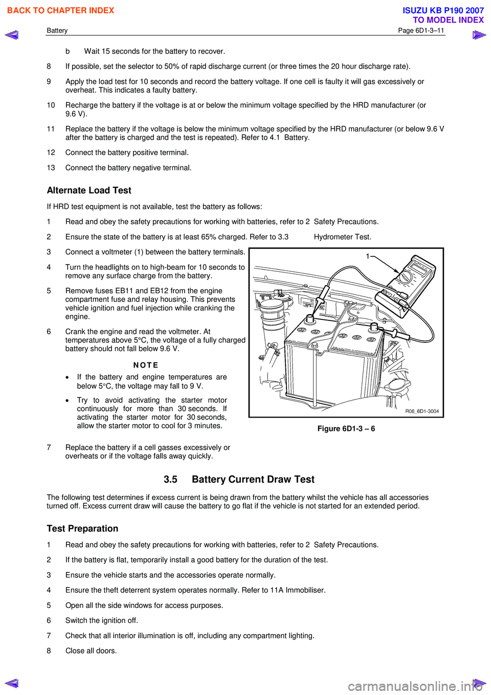
3 Connect a voltmeter (1) between the battery terminals.
4 Turn the headlights on to high-beam for 10 seconds to remove any surface charge from the battery.
5 Remove fuses EB11 and EB12 from the engine compartment fuse and relay housing. This prevents
vehicle ignition and fuel injection while cranking the
engine.
6 Crank the engine and read the voltmeter. At temperatures above 5°C, the voltage of a fully charged
battery should not fall below 9.6 V.
NOTE
• If the battery and engine temperatures are
below 5 °C, the voltage may fall to 9 V.
• Try to avoid activating the starter motor
continuously for more than 30 seconds. If
activating the starter motor for 30 seconds,
allow the starter motor to cool for 3 minutes.
7 Replace the battery if a cell gasses excessively or overheats or if the voltage falls away quickly.
Figure 6D1-3 – 6
3.5 Battery Current Draw Test
The following test determines if excess current is being drawn from the battery whilst the vehicle has all accessories
turned off. Excess current draw will cause the battery to go flat if the vehicle is not started for an extended period.
Test Preparation
1 Read and obey the safety precautions for working with batteries, refer to 2 Safety Precautions.
2 If the battery is flat, temporarily install a good battery for the duration of the test.
3 Ensure the vehicle starts and the accessories operate normally.
4 Ensure the theft deterrent system operates normally. Refer to 11A Immobiliser.
5 Open all the side windows for access purposes.
6 Switch the ignition off.
7 Check that all interior illumination is off, including any compartment lighting.
8 Close all doors.
BACK TO CHAPTER INDEX
TO MODEL INDEX
ISUZU KB P190 2007
Page 3653 of 6020
Battery Page 6D1-3–13
3 W hen the circuit group is determined, install the fuse / circuit breaker and identify the specific circuit within this
group that is drawing the excess current. Disconnect the wiring harness connectors in this circuit group one at a
time. Refer to 8A Electrical Body & Chassis.
4 W hen the cause is disconnected, the multimeter reading should drop to the correct reading as outlined in Step 9 of the Test Procedure in this Section.
5 If required, remove the components in this circuit one at a time to determine the cause of the excessive standing current. Refer to 8A Electrical Body & Chassis.
6 Repair the fault, refer to 8A Electrical Body & Chassis.
7 Ensure any fuses, circuit breakers and connectors that have been removed are secure.
Restore
1 Reconnect the electrical earth cable to the battery terminal and tighten the nut to the correct torque specification.
Battery terminal nut
torque specification .....................................2.0 – 5.0 Nm
2 Disconnect the multimeter connections.
BACK TO CHAPTER INDEX
TO MODEL INDEX
ISUZU KB P190 2007
Page 3655 of 6020
Battery Page 6D1-3–15
5 Install the positive terminal onto the positive battery post. Ensure the terminal sits below the top of the post and
tighten the terminal nut to the correct specification.
Battery terminal nut
torque specification .....................................2.0 – 5.0 Nm
6 Install the negative terminal onto the negative battery post. Ensure the terminal sits below the top of the post and tighten the terminal nut to the correct specification.
Battery terminal nut
torque specification .....................................2.0 – 5.0 Nm
7 Smear the battery posts and cable terminals with petroleum jelly to inhibit corrosion.
4.2 Battery Charge
Safety Precautions
Read and obey the general safety precautions for working with batteries, refer to 2 Safety Precautions.
The battery releases an explosive hydrogen and oxygen gas mixture during charging. Ensure there are no naked flames
or sparks near the battery.
Flat batteries can be safely boost-charged, however avoid excessive charging current if the battery is more than half
charged. Slow charging is best.
Fast charging can substantially boost a battery, but slow charging is required to fully charge the battery.
Do not use a fast charger:
• for starting the vehicle,
• if the specific gravity readings are not uniform between battery cells, refer to 3.3 Hydrometer Test,
• if the specific gravity readings are above 1.20, refer to 3.3Hydrometer Test,
• if the electrolyte is discoloured with brown sediment, and
• if any of the above three conditions develop after beginning a fast charge.
Battery Charge Procedure
Disconnection of the battery affects certain
vehicle electronic systems. Refer to Warning,
Caution and Notes in this section before
disconnecting the battery.
1 Perform steps 1 to 10 of the battery inspection, refer to 3.2 Battery Inspection.
2 Remove the battery from the vehicle. Refer to 4.1 Battery.
3 If required remove the battery filler caps. Let the caps rest loosely on top of the filler tubes.
Always ensure the connections are to the
correct polarity and follow the manufacturer’s
recommendations for battery charging.
4 Connect the battery to the battery charger.
5 Set the charging current using the following table as a guide.
BACK TO CHAPTER INDEX
TO MODEL INDEX
ISUZU KB P190 2007
Page 3657 of 6020

Battery Page 6D1-3–17
4 Turn off the ignition, lights and all other electrical loads.
5 Check the battery filler caps on both batteries are tight.
6 Place a wet cloth over the battery filler caps of each battery.
7 Attach one end of the red jumper cable to the positive terminal of the booster battery.
8 Attach the other end of the same cable to the positive terminal of the discharged battery.
9 Attach one end of the black jumper cable to the negative terminal of the booster battery.
10 Attach the other end to a solid stationary, metallic point on the engine of the disabled vehicle.
NOTE
Do not connect this end directly to the negative
post of the discharged battery.
Figure 6D1-3 – 10
Legend
Order of hook-up:
1 Booster vehicle, positive terminal
2 Disabled vehicle, positive terminal
3 Booster vehicle, negative terminal
4 Disabled vehicle, engine ground point Booster vehicle
Disabled vehicle
11 Ensure the jumper cables are not on or near drive pulleys, cooling fans or other points that will move when the engine is started.
12 Start the engine in the booster vehicle and run the engine at a moderate speed for a few minutes.
13 Start the engine in the disabled vehicle.
NOTE
If the engine in the disabled vehicle does not start
within 30 seconds, stop cranking the engine and
fix the cause. Refer to 3 Diagnosis.
14 W hen the engine starts, allow both engines to idle for approximately seven minutes. This allows the voltage levels in both vehicles to balance.
15 Leave the vehicles running and remove the jumper cables in the reverse sequence to attaching them. W hen removing each clamp, take care to ensure that it does not touch any other metal.
16 Discard the wet cloths covering the battery filler caps of both batteries.
BACK TO CHAPTER INDEX
TO MODEL INDEX
ISUZU KB P190 2007
Page 3658 of 6020
Battery Page 6D1-3–18
4.4 Dry Charged Batteries
Storage
Dry charged batteries are fully charged when manufactured and contain no electrolyte until activated. The dry charged
can be stored indefinitely with no servicing until activated.
Activation
1 Remove the battery filler caps.
2 Add 1.265 specific gravity electrolyte to each cell to the correct level.
3 W ait several minutes.
4 Check the electrolyte level and add more electrolyte (not water) as required. After a dry charged battery is activated, it becomes a wet battery.
Post Activation Tests
Although a dry charged battery can be put into service immediately after activation, the following tests are recommended:
1 Check the voltage of the battery after adding the electrolyte.
2 If the reading is less than 10 V, replace the battery.
3 Check the specific gravity of the electrolyte in each cell, refer to 3.3 Hydrometer Test.
4 If any reading shows more than a 0.030 drop from the initial electrolyte reading, slow-charge the battery before use. Refer to 4.2 Battery Charge.
5 Check the cells for violent gassing. If violent gassing is detected evenly across all cells, slow-charge the battery before use. If violent gassing is not even across all cells, replace the battery.
BACK TO CHAPTER INDEX
TO MODEL INDEX
ISUZU KB P190 2007
Page 3659 of 6020
Battery Page 6D1-3–19
5 Specifications
Rated Voltage ................................................................................................................... 12 V
Cold Cranking Amps ........................................................................................ 430 A minimum
Reserve Capacity ....................................................................................85 minutes minimum
20 Hour Discharge ...................................................................................55 A / hour minimum
5 Second Voltage @ 25 °
C .................................................................... 150 A 10.4 + / – 0.2 V
................................................................................................................. 400 A 8.4 + / – 0.2 V
Number of Plates (per cell) ................................................................................................... 1 1
NOTE
Specified ratings when tested in accordance with
Australian Standard AS 2149-1990
BACK TO CHAPTER INDEX
TO MODEL INDEX
ISUZU KB P190 2007