2007 ISUZU KB P190 Harness
[x] Cancel search: HarnessPage 4869 of 6020
TRANSFER CASE 7D-39
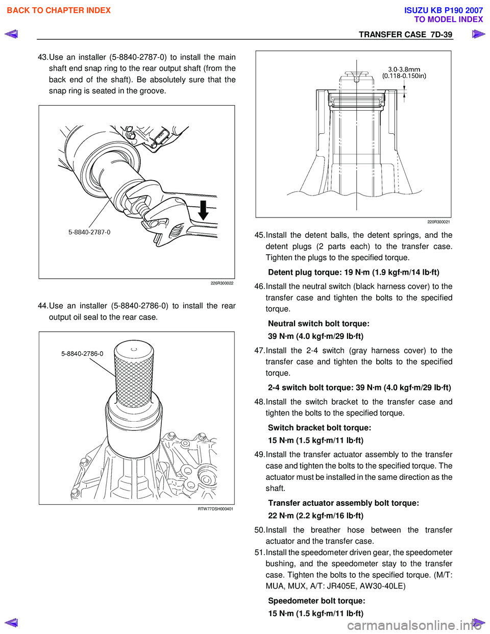
43. Use an installer (5-8840-2787-0) to install the main
shaft end snap ring to the rear output shaft (from the
back end of the shaft). Be absolutely sure that the
snap ring is seated in the groove.
226R300022
44. Use an installer (5-8840-2786-0) to install the rear
output oil seal to the rear case.
RTW 77DSH000401
220R300021
45.
Install the detent balls, the detent springs, and the
detent plugs (2 parts each) to the transfer case.
Tighten the plugs to the specified torque.
Detent plug torque: 19 N ·m (1.9 kgf ·m/14 lb ·ft)
46. Install the neutral switch (black harness cover) to the
transfer case and tighten the bolts to the specified
torque.
Neutral switch bolt torque:
39 N ·m (4.0 kgf ·m/29 lb ·ft)
47. Install the 2-4 switch (gray harness cover) to the
transfer case and tighten the bolts to the specified
torque.
2-4 switch bolt torque: 39 N ·m (4.0 kgf ·m/29 lb ·ft)
48. Install the switch bracket to the transfer case and
tighten the bolts to the specified torque.
Switch bracket bolt torque:
15 N ·m (1.5 kgf ·m/11 lb ·ft)
49. Install the transfer actuator assembly to the transfe
r
case and tighten the bolts to the specified torque. The
actuator must be installed in the same direction as the
shaft.
Transfer actuator assembly bolt torque:
22 N ·m (2.2 kgf ·m/16 lb ·ft)
50. Install the breather hose between the transfe
r
actuator and the transfer case.
51. Install the speedometer driven gear, the speedomete
r
bushing, and the speedometer stay to the transfe
r
case. Tighten the bolts to the specified torque. (M/T:
MUA, MUX, A/T: JR405E, AW 30-40LE)
Speedometer bolt torque:
15 N ·m (1.5 kgf ·m/11 lb ·ft)
BACK TO CHAPTER INDEX
TO MODEL INDEX
ISUZU KB P190 2007
Page 4880 of 6020
7D1-6 TRANSFER CONTROL SYSTEM
the 4×2 - 4 ×4 shift rod. W hen moving in 4 ×2 direction, a spring
standby mechanism is provided between the rod and sleeve so
that the rod is positioned at the 4 ×2 position, while the sleeve is
at the 4 ×4 position.
This mechanism is provided to protect the shift mechanism
from the force and to prevent movement of the sleeve
(torsional torque etc. of the drive system). By releasing the
preventive force, the sleeve can move to the 4 ×2 state by the
spring force.
Neutral switch
The neutral switch detects the movement of the shift rod
driving the high-low sleeve.
PUSH close is achieved with the PUSH close switch when the
shift rod is positioned between the High and the Low, at the
neutral state.
High-Low Sleeve & Arm
The spring standby mechanism is provided for the high-low
sleeve in both directions of the high-low shift rod. Therefore,
the rod position and the actual sleeve position may be offset in
some cases.
This system is provided to protect the shift mechanism from a
collision due to coincidence of the high and low phases of the
engaged splines. By giving rotational force to the preventing
phase coincidence, the splines are moved to the proper
engagement position by the spring force.
Shift actuator
The output shaft is rotated by the built-in motor and the transfer
position is switched.
Detection (limit) switches to detect the rotating angle of the
output shaft that is provided to the actuator at 4 positions.
These are connected to the transfer controller through the
vehicle harness to constantly transmit the actuator operating
angle and changes in its transfer status.
7B4-PDF2
4WD indicator (in meter panel)
This lamp indicates the following items:
Valve check
Drive condition (2W D-4W D)
Operating condition (2Hz: Actuator in operation, mechanism
standby)
Restrictions on operation (4Hz, including indication of
interrupted operation due
to excessive load)
BACK TO CHAPTER INDEX
TO MODEL INDEX
ISUZU KB P190 2007
Page 4885 of 6020
TRANSFER CONTROL SYSTEM 7D1-11
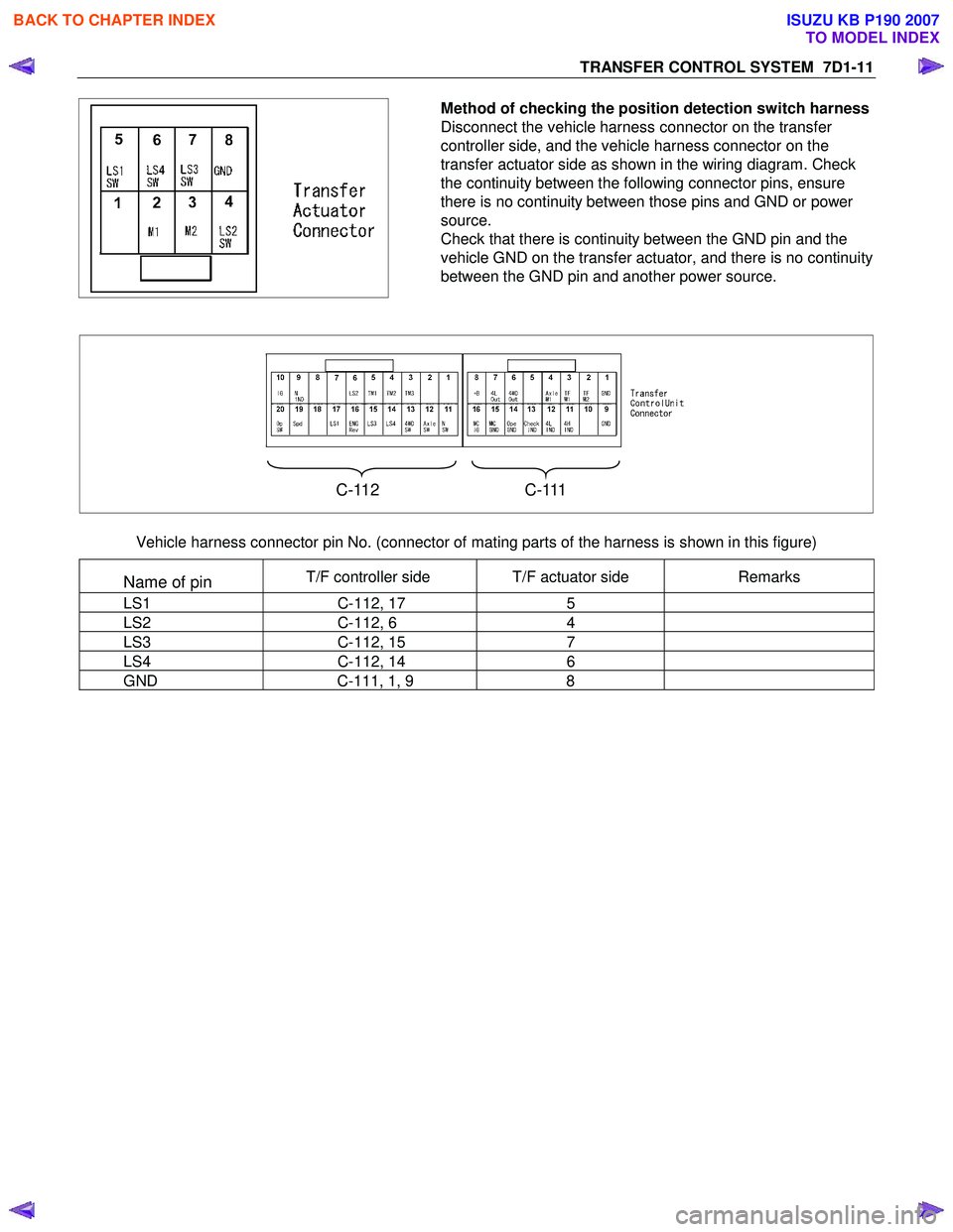
Method of checking the position detection switch harness
Disconnect the vehicle harness connector on the transfer
controller side, and the vehicle harness connector on the
transfer actuator side as shown in the wiring diagram. Check
the continuity between the following connector pins, ensure
there is no continuity between those pins and GND or power
source.
Check that there is continuity between the GND pin and the
vehicle GND on the transfer actuator, and there is no continuity
between the GND pin and another power source.
C-112 C-111
Vehicle harness connector pin No. (connector of mating parts of the harness is shown in this figure)
Name of pin T/F controller side T/F actuator side Remarks
LS1 C-112, 17 5
LS2 C-112, 6 4
LS3 C-112, 15 7
LS4 C-112, 14 6
GND C-111, 1, 9 8
BACK TO CHAPTER INDEX
TO MODEL INDEX
ISUZU KB P190 2007
Page 4925 of 6020
TRANSFER CONTROL SYSTEM 7D1-51
Trouble diagnosis based on the operation switch, transfer indicator lamp and operating
sound “Check 4WD” indicator ON (operation guard based on the transfer actuator
position detection error)
This condition indicates a faulty circuit related with the detection (limit) switches of the system actuator.
Detection (limit) switches detect the actuator operating angle based on their combinations.
The controller monitors transition of the actuator based on the combination of the detection (limit) switch output.
If the transition based on the combinations indicates some trouble, it is memorized, and shifting operation is
stopped when the trouble is counted 5 times, and the “Check 4W D” indicator lights up. At this time, the system
permits operation to 2H only.
W hen such a condition occurs, inspection of the transfer shift actuator, checking of the harness related with the
detection (limit) switch, and erasure of the memory of the controller is required.
(Refer to the memory erasure procedure for the erasure of the memory.)
At this time, the position indicator may flash at 4Hz. It means that a detection (limit) switch trouble wad detected
in the operation process shown by that position indicator (example: 4W D indicator when shifting from 2H to 4H).
Caution:
During trouble diagnosis and correction, do not turn ON the ignition with the harness connector of the
transfer actuator disconnected. (Do not disconnect the harness connector of the transfer actuator when
the ignition is ON.)
If the controller is connected during this condition, a limit SW trouble is judged and the above-described
“Check 4WD” condition occurs.
This can be reset by clearing the memory.
When disconnecting the harness connector of the actuator and turning the ignition ON is required, remove
the controller at the same time or remove the IG power fuse of the transfer controller.
BACK TO CHAPTER INDEX
TO MODEL INDEX
ISUZU KB P190 2007
Page 4926 of 6020
7D1-52 TRANSFER CONTROL SYSTEM
Memory erasing procedure
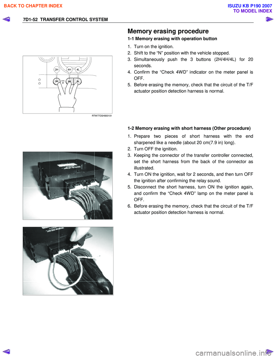
1-1 Memory erasing with operation button
1. Turn on the ignition.
2. Shift to the “N” position with the vehicle stopped.
RTW 77DSH000101
3. Simultaneously push the 3 buttons (2H/4H/4L) for 20
seconds.
4. Confirm the “Check 4W D” indicator on the meter panel is OFF.
5. Before erasing the memory, check that the circuit of the T/F actuator position detection harness is normal.
1-2 Memory erasing with short harness (Other procedure)
1. Prepare two pieces of short harness with the end sharpened like a needle (about 20 cm(7.9 in) long).
2. Turn OFF the ignition.
3. Keeping the connector of the transfer controller connected,
set the short harness from the back of the connector as
illustrated.
4. Turn ON the ignition, wait for 2 seconds, and then turn OFF the ignition after confirming the relay sound.
5. Disconnect the short harness, turn ON the ignition again, and confirm the “Check 4W D” lamp on the meter panel is
OFF.
6. Before erasing the memory, check that the circuit of the T/F actuator position detection harness is normal.
BACK TO CHAPTER INDEX
TO MODEL INDEX
ISUZU KB P190 2007
Page 4928 of 6020
7D1-54 TRANSFER CONTROL SYSTEM
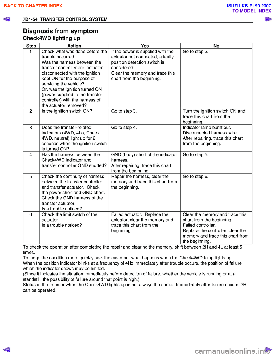
Diagnosis from symptom
Check4WD lighting up
Step Action Yes No
1 Check what was done before the
trouble occurred.
W as the harness between the
transfer controller and actuator
disconnected with the ignition
kept ON for the purpose of
servicing the vehicle?
Or, was the ignition turned ON
(power supplied to the transfer
controller) with the harness of
the actuator removed? If the power is supplied with the
actuator not connected, a faulty
position detection switch is
considered.
Clear the memory and trace this
chart from the beginning. Go to step 2.
2
Is the ignition switch ON? Go to step 3.
Turn the ignition switch ON and
trace this chart from the
beginning.
3 Does the transfer-related
indicators (4W D, 4Lo, Check
4W D, neutral) light up for 2
seconds when the ignition switch
is turned ON? Go to step 4.
Indicator lamp burnt out.
Disconnected harness wire.
After repairing, trace this chart
from the beginning.
4 Has the harness between the
Check4W D indicator and
transfer controller GND shorted? GND (body) short of the indicator
harness.
After repairing, trace this chart
from the beginning. Go to step 5.
5
Check the continuity of harness
between the transfer controller
and transfer actuator. Check
the power short and GND short.
Check the GND harness of the
transfer actuator.
Is a trouble noticed? Repair the harness, clear the
memory and trace this chart from
the beginning. Go to step 6.
6
Check the limit switch of the
actuator.
Is a trouble noticed? Failed actuator. Replace the
actuator, clear the memory and
trace this chart from the
beginning. Clear the memory and trace this
chart from the beginning.
Failed controller.
Replace the controller, clear the
memory and trace this chart from
the beginning.
To check the operation after completing the repair and clearing the memory, shift between 2H and 4L at least 5
times.
To judge the condition more quickly, ask the customer what happens when the Check4W D lamp lights up.
W hen the position indicator blinks at a frequency of 4Hz immediately after trouble occurs, the position of failure
which the indicator shows may be limited.
(Since it indicates the situation immediately before detection of failure, whether the vehicle is running or at a
standstill, the possibility of failure around that point is high.)
Status of the transfer when the Check4W D lights up is not always the same. Immediately after failure occurs, 2H
can be operated.
BACK TO CHAPTER INDEX
TO MODEL INDEX
ISUZU KB P190 2007
Page 4929 of 6020
TRANSFER CONTROL SYSTEM 7D1-55
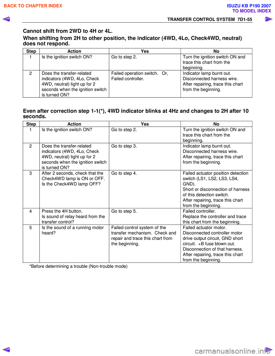
Cannot shift from 2WD to 4H or 4L.
When shifting from 2H to other position, the indicator (4WD, 4Lo, Check4WD, neutral)
does not respond.
Step Action Yes No
1 Is the ignition switch ON? Go to step 2.
Turn the ignition switch ON and
trace this chart from the
beginning.
2 Does the transfer-related
indicators (4W D, 4Lo, Check
4W D, neutral) light up for 2
seconds when the ignition switch
is turned ON? Failed operation switch. Or,
Failed controller. Indicator lamp burnt out.
Disconnected harness wire.
After repairing, trace this chart
from the beginning.
Even after correction step 1-1(*), 4WD indicator blinks at 4Hz and changes to 2H after 10
seconds.
Step Action Yes No
1 Is the ignition switch ON? Go to step 2.
Turn the ignition switch ON and
trace this chart from the
beginning.
2 Does the transfer-related
indicators (4W D, 4Lo, Check
4W D, neutral) light up for 2
seconds when the ignition switch
is turned ON? Go to step 3.
Indicator lamp burnt out.
Disconnected harness wire.
After repairing, trace this chart
from the beginning.
3 After 2 seconds, check that the
Check4W D lamp is ON or OFF.
Is the Check4W D lamp OFF? Go to step 4.
Failed actuator position detection
switch (LS1, LS2, LS3, LS4,
GND).
Short or disconnection of harness
of this detection switch.
After repairing, trace this chart
from the beginning.
4 Press the 4H button.
Is sound of relay heard from the
transfer control? Go to step 5.
Failed controller.
Replace the controller and trace
this chart from the beginning.
5 Is the sound of a running motor
heard? Failed control system of the
transfer mechanism. Check and
repair and trace this chart from
the beginning. Failed actuator motor.
Disconnected controller motor
drive output circuit, GND short
circuit. +B fuse blown out.
Disconnection of that harness.
After repairing, trace this chart
from the beginning.
*Before determining a trouble (Non-trouble mode)
BACK TO CHAPTER INDEX
TO MODEL INDEX
ISUZU KB P190 2007
Page 4930 of 6020
7D1-56 TRANSFER CONTROL SYSTEM
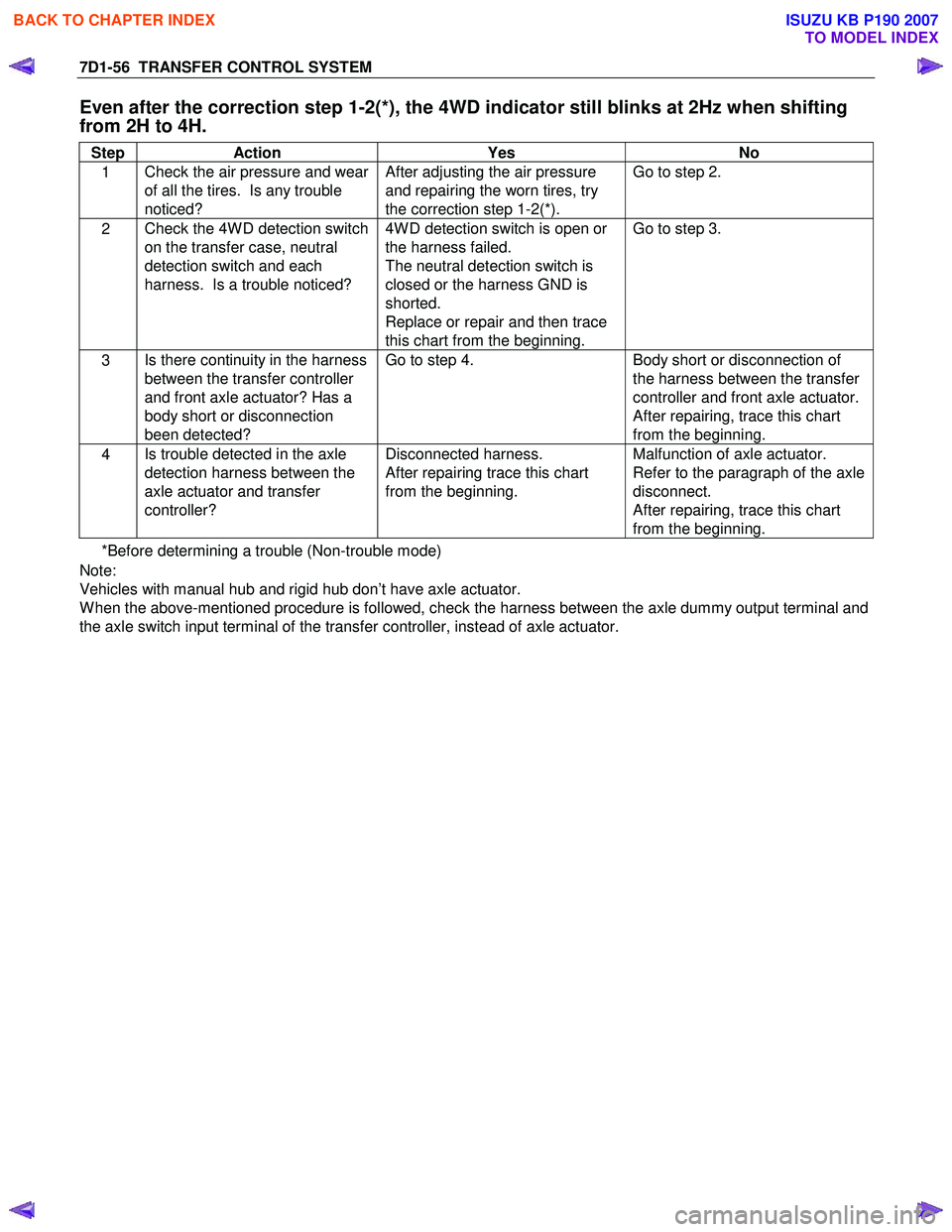
Even after the correction step 1-2(*), the 4WD indicator still blinks at 2Hz when shifting
from 2H to 4H.
Step Action Yes No
1 Check the air pressure and wear
of all the tires. Is any trouble
noticed? After adjusting the air pressure
and repairing the worn tires, try
the correction step 1-2(*). Go to step 2.
2
Check the 4W D detection switch
on the transfer case, neutral
detection switch and each
harness. Is a trouble noticed? 4W D detection switch is open or
the harness failed.
The neutral detection switch is
closed or the harness GND is
shorted.
Replace or repair and then trace
this chart from the beginning. Go to step 3.
3
Is there continuity in the harness
between the transfer controller
and front axle actuator? Has a
body short or disconnection
been detected? Go to step 4.
Body short or disconnection of
the harness between the transfer
controller and front axle actuator.
After repairing, trace this chart
from the beginning.
4 Is trouble detected in the axle
detection harness between the
axle actuator and transfer
controller? Disconnected harness.
After repairing trace this chart
from the beginning. Malfunction of axle actuator.
Refer to the paragraph of the axle
disconnect.
After repairing, trace this chart
from the beginning.
*Before determining a trouble (Non-trouble mode)
Note:
Vehicles with manual hub and rigid hub don’t have axle actuator.
W hen the above-mentioned procedure is followed, check the harness between the axle dummy output terminal and
the axle switch input terminal of the transfer controller, instead of axle actuator.
BACK TO CHAPTER INDEX
TO MODEL INDEX
ISUZU KB P190 2007