Page 4731 of 6020

7B1-12 Manual Transmission (MUX)
22. Remove the transmission retaining nuts and bolts.Remove the transmission assembly (4x2 model) or
the transmission & transfer assembly (4x4 model)
from the vehicle.
23. Remove the transmission-transfer fixing bolts and nut, and disassemble the transfer from the
transmission. (4x4 model)
Installation
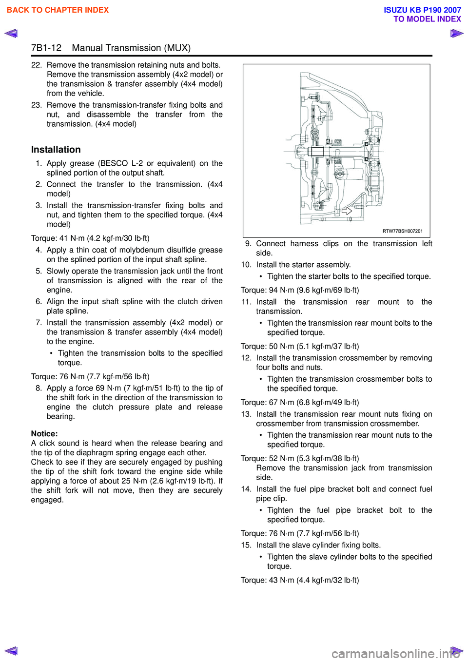
1. Apply grease (BESCO L-2 or equivalent) on the splined portion of the output shaft.
2. Connect the transfer to the transmission. (4x4 model)
3. Install the transmission-transfer fixing bolts and nut, and tighten them to the specified torque. (4x4
model)
Torque: 41 N ⋅m (4.2 kgf ⋅m/30 lb ⋅ft)
4. Apply a thin coat of molybdenum disulfide grease on the splined portion of the input shaft spline.
5. Slowly operate the transmission jack until the front of transmission is aligned with the rear of the
engine.
6. Align the input shaft spline with the clutch driven plate spline.
7. Install the transmission assembly (4x2 model) or the transmission & transfer assembly (4x4 model)
to the engine.
• Tighten the transmission bolts to the specified torque.
Torque: 76 N ⋅m (7.7 kgf ⋅m/56 lb ⋅ft)
8. Apply a force 69 N ⋅m (7 kgf ⋅m/51 lb ⋅ft) to the tip of
the shift fork in the direction of the transmission to
engine the clutch pressure plate and release
bearing.
Notice:
A click sound is heard when the release bearing and
the tip of the diaphragm spring engage each other.
Check to see if they are securely engaged by pushing
the tip of the shift fork toward the engine side while
applying a force of about 25 N ⋅m (2.6 kgf ⋅m/19 lb ⋅ft). If
the shift fork will not move, then they are securely
engaged. 9. Connect harness clips on the transmission left
side.
10. Install the starter assembly.
• Tighten the starter bolts to the specified torque.
Torque: 94 N ⋅m (9.6 kgf ⋅m/69 lb ⋅ft)
11. Install the transmission rear mount to the transmission.
• Tighten the transmission rear mount bolts to the specified torque.
Torque: 50 N ⋅m (5.1 kgf ⋅m/37 lb ⋅ft)
12. Install the transmission crossmember by removing four bolts and nuts.
• Tighten the transmission crossmember bolts to the specified torque.
Torque: 67 N ⋅m (6.8 kgf ⋅m/49 lb ⋅ft)
13. Install the transmission rear mount nuts fixing on crossmember from transmission crossmember.
• Tighten the transmission rear mount nuts to the specified torque.
Torque: 52 N ⋅m (5.3 kgf ⋅m/38 lb ⋅ft)
Remove the transmission jack from transmission
side.
14. Install the fuel pipe bracket bolt and connect fuel pipe clip.
• Tighten the fuel pipe bracket bolt to the specified torque.
Torque: 76 N ⋅m (7.7 kgf ⋅m/56 lb ⋅ft)
15. Install the slave cylinder fixing bolts. • Tighten the slave cylinder bolts to the specifiedtorque.
Torque: 43 N ⋅m (4.4 kgf ⋅m/32 lb ⋅ft)
RTW77BSH007201
BACK TO CHAPTER INDEX
TO MODEL INDEX
ISUZU KB P190 2007
Page 4732 of 6020
Manual Transmission (MUX) 7B1-13
16. Install the front propeller shaft. (4x4 model)• Tighten the front propeller shaft bolts to thespecified torque.
Torque: 59 N ⋅m (6.0 kgf ⋅m/43 lb ⋅ft)
17. Install the rear propeller shaft.
• Tighten the rear propeller shaft bolts to thespecified torque.
Torque
Rear flange: 59 N ⋅m (6.0 kgf ⋅m/43 lb ⋅ft)
Center bearing: 69 N ⋅m (7.0 kgf ⋅m/51 lb ⋅ft)
18. Connect harness clip on the transmission left side bracket.
Install the harness bracket bolt.
• Tighten the harness bracket bolt to the specified torque.
Torque: 23 N ⋅m (2.3 kgf ⋅m/17 lb ⋅ft) 19. Connect the harness connectors and clips on the
transmission.
Legend 1. Neutral switch connector
2. Clutch damper valve connector
Legend 3. Clip
4. Reverse switch connector
5. 1st switch connector
RTW77BSH000301
RTW77BSH006601
1
2
RTW77BSH006701
3
3 54
BACK TO CHAPTER INDEX
TO MODEL INDEX
ISUZU KB P190 2007
Page 4738 of 6020

Manual Transmission (MUX) 7B1-19
b. Remove the taper bolt, and discard the usedtaper bolt.
c. Remove the control unit block.
7. Remove the reverse switch (Connector color Brown), 1st switch (Connector color Gray) and
neutral switch (Connector color Brown) with
gasket.
Remove the three detent assemblies, and discard
the used 5th & reverse detent assemblies.
8. Remove the two harness brackets.
9. Remove the speedometer driven gear and plate. (4x2 model)
10. Remove the end cover assembly. 11. Remove the gear set clip. (4x2 model)
12. Remove the speedometer drive gear. (4x2 model)
13. Stand the transmission assembly.
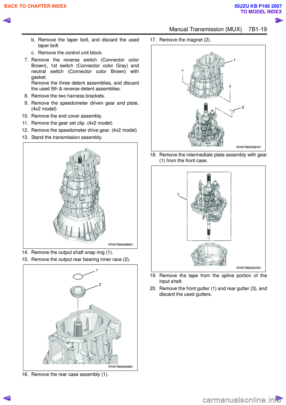
14. Remove the output shaft snap ring (1).
15. Remove the output rear bearing inner race (2).
16. Remove the rear case assembly (1). 17. Remove the magnet (2).
18. Remove the intermediate plate assembly with gear (1) from the front case.
19. Remove the tape from the spline portion of the input shaft.
20. Remove the front gutter (1) and rear gutter (3), and discard the used gutters.
RTW77BSH006001
RTW77BSH003901
2
1
RTW77BSH008101
1
2
RTW77BSH007501
1
BACK TO CHAPTER INDEX
TO MODEL INDEX
ISUZU KB P190 2007
Page 4751 of 6020

7B1-32 Manual Transmission (MUX)
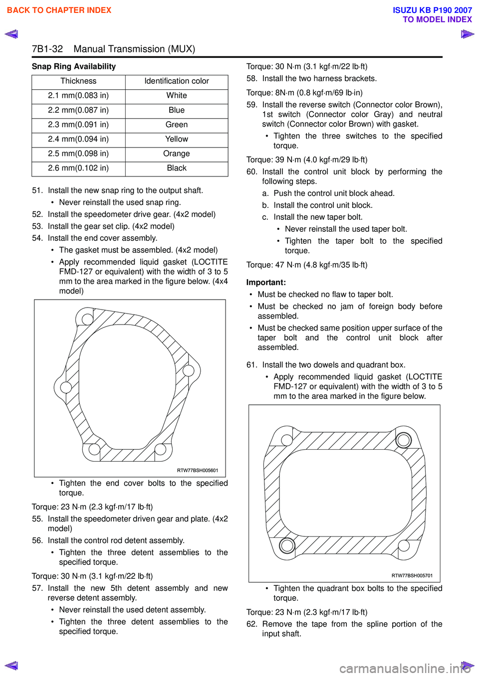
Snap Ring Availability51. Install the new snap ring to the output shaft. • Never reinstall the used snap ring.
52. Install the speedometer drive gear. (4x2 model)
53. Install the gear set clip. (4x2 model)
54. Install the end cover assembly.
• The gasket must be assembled. (4x2 model)
• Apply recommended liquid gasket (LOCTITE FMD-127 or equivalent) with the width of 3 to 5
mm to the area marked in the figure below. (4x4
model)
• Tighten the end cover bolts to the specified torque.
Torque: 23 N ⋅m (2.3 kgf ⋅m/17 lb ⋅ft)
55. Install the speedometer driven gear and plate. (4x2 model)
56. Install the control rod detent assembly.
• Tighten the three detent assemblies to thespecified torque.
Torque: 30 N ⋅m (3.1 kgf ⋅m/22 lb ⋅ft)
57. Install the new 5th detent assembly and new reverse detent assembly.
• Never reinstall the used detent assembly.
• Tighten the three detent assemblies to the specified torque. Torque: 30 N
⋅m (3.1 kgf ⋅m/22 lb ⋅ft)
58. Install the two harness brackets.
Torque: 8N ⋅m (0.8 kgf ⋅m/69 lb ⋅in)
59. Install the reverse switch (Connector color Brown), 1st switch (Connector color Gray) and neutral
switch (Connector color Brown) with gasket.
• Tighten the three switches to the specified torque.
Torque: 39 N ⋅m (4.0 kgf ⋅m/29 lb ⋅ft)
60. Install the control unit block by performing the following steps.
a. Push the control unit block ahead.
b. Install the control unit block.
c. Install the new taper bolt.
• Never reinstall the used taper bolt.
• Tighten the taper bolt to the specified torque.
Torque: 47 N ⋅m (4.8 kgf ⋅m/35 lb ⋅ft)
Important: • Must be checked no flaw to taper bolt.
• Must be checked no jam of foreign body before assembled.
• Must be checked same position upper surface of the taper bolt and the control unit block after
assembled.
61. Install the two dowels and quadrant box. • Apply recommended liquid gasket (LOCTITEFMD-127 or equivalent) with the width of 3 to 5
mm to the area marked in the figure below.
• Tighten the quadrant box bolts to the specified torque.
Torque: 23 N ⋅m (2.3 kgf ⋅m/17 lb ⋅ft)
62. Remove the tape from the spline portion of the input shaft.
Thickness
Identification color
2.1 mm(0.083 in) White
2.2 mm(0.087 in) Blue
2.3 mm(0.091 in) Green
2.4 mm(0.094 in) Yellow
2.5 mm(0.098 in) Orange
2.6 mm(0.102 in) Black
RTW77BSH005601
RTW77BSH005701
BACK TO CHAPTER INDEX
TO MODEL INDEX
ISUZU KB P190 2007
Page 4842 of 6020

7D-12 TRANSFER CASE
Removal
NOTE: Before removing transmission and transfer
assembly from vehicle, change the transfer mode to
2W D using the 4W D push button switch on dash panel.
1. Disconnect battery ground cable.
2. Raise and support vehicle with suitable stands. Drain
transfer case fluid.
3. Remove rear propeller shaft and front propeller shaft.
NOTE: Apply alignment marks on the flange at both front
and rear sides.
4. Disconnect harness connectors and clip.
Connector: transfer switch, 2W D-4W D actuator,
speed sensor.
NOTE: Avoid turning the vehicle ignition switch to the ON
position when the 2W D-4W D connector is removed
(battery connected).
If the ignition switch must be turned to the ON position,
the controller must first be removed (memory must be
cleared because the CHECK 4W D INDICATOR will
light).
5. Remove transfer case assembly from the vehicle.
Installation
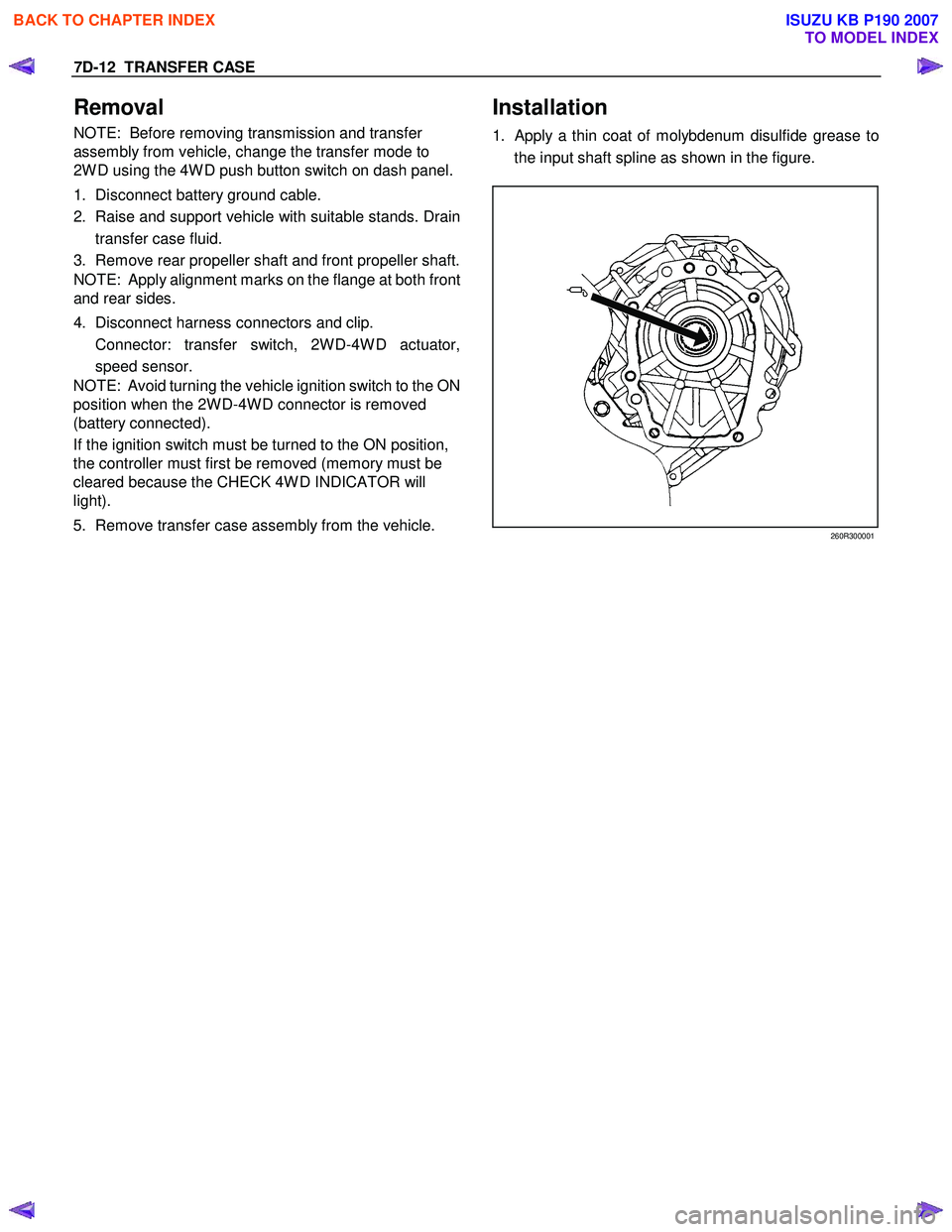
1. Apply a thin coat of molybdenum disulfide grease to
the input shaft spline as shown in the figure.
260R300001
BACK TO CHAPTER INDEX
TO MODEL INDEX
ISUZU KB P190 2007
Page 4845 of 6020
TRANSFER CASE 7D-15
For M/T (AR-5), A/T (4L60-E)
N⋅
⋅⋅
⋅
m (kgf ⋅
⋅⋅
⋅
m/lb ⋅
⋅⋅
⋅
ft)
mm (in)
RTW 77DLF000401
3. Connect harness connectors and clip.
Connector: transfer switch, 2W D-4W D actuator,
speed sensor.
4. Install rear propeller shaft and front propeller shaft.
Propeller shaft torque: 59 N ⋅
⋅⋅
⋅
m (6.0 kgf ⋅
⋅⋅
⋅
m/43 lb ⋅
⋅⋅
⋅
ft)
BACK TO CHAPTER INDEX
TO MODEL INDEX
ISUZU KB P190 2007
Page 4847 of 6020
TRANSFER CASE 7D-17
LHD
RTW 77DMF000101
Legend
(1) Transfer Control Unit
(2) Nut
Removal
1. Disconnect the battery ground cable.
2. Disconnect the harness connector from the Transfe
r
control unit.
3. Remove the Transfer control unit.
Installation
1. Install the Transfer control unit.
Transfer control unit torque: 7 N ⋅
⋅⋅
⋅
m (0.7 kgf ⋅
⋅⋅
⋅
m/61 lb ⋅
⋅⋅
⋅
in)
2. Connect the harness connector to the Transfe
r
control unit.
3. Connect the battery ground cable.
BACK TO CHAPTER INDEX
TO MODEL INDEX
ISUZU KB P190 2007
Page 4849 of 6020
TRANSFER CASE 7D-19
• Breather hose (Between the transfer case and the
transfer actuator assembly)
• Transfer actuator assembly
• Switch bracket
• 2-4 switch assembly (Gray harness cover)
• Neutral switch assembly (Black harness cover)
• Detent plugs, detent springs, and detent balls (2
parts each)
4. Use a flange holder (5-8840-0133-0) to remove the
end nut from the front companion flange.
RTW 77DSH000201
5. Remove the bolts attaching the rear cover to the
transfer case.
6. Strike the area around the front output shaft head and
the rear cover bolt holes with a plastic hammer to
remove the rear cover.
220R300022
BACK TO CHAPTER INDEX
TO MODEL INDEX
ISUZU KB P190 2007