2007 ISUZU KB P190 Harness
[x] Cancel search: HarnessPage 4424 of 6020
7A2-140 TRANSMISSION CONTROL SYSTEM (JR405E)
• Electrically Erasable Programmable Read OnlyMemory (EEPROM)
This type of memory allows selected portions of
memory to be programmed while other portions
remain unchanged.
Certain learned values reside in the EEPROM,
such as:
- The vehicle identification number (VIN)
- The software/ calibrations identification numbers
- The control module security information
• Flash Read Only Memory-Flash Memory
Flash memory has increased memory storage capacity.
During programming, all information within this type of
memory is erased, and then replaced with entirely new
information.
Service Programming Methods
The two methods of programming a TCM are listed
below:
• Remote Programming
• Pass Thru Programming
For information on programming a TCM using one of
the methods listed above, refer to Service
Programming System (SPS) (Remote Procedure) or
Service Programming System (SPS) (Pass-Thru
Procedure).
Before Programming a Control Module
Important: DO NOT program an existing TCM with the
identical software/ calibration package. This procedure
is not a short cut to correct the driveability condition.
This is an ineffective repair. An TCM should only be
programmed when the following occurs:
• When a service procedure instructs you to replace the TCM.
• An updated software/ calibrations is released.
Ensure that the following conditions are met before
programming a TCM:
• The scan tool PCMCIA card is programmed with the latest software.
• The TIS 2000 is installed with the latest software.
• The hardware key is plugged into the computer port.
• Vehicle system voltage:
- There are no charging system concerns. Allcharging system concerns must be repaired
before programming the TCM.
- The battery voltage is greater than 12 volts but less than 16 volts. The battery must be fully
charged before programming the TCM.
- A battery charger is NOT connected to the vehicles battery. Incorrect system voltage or
voltage fluctuations from a battery charger may
cause programming failure or TCM damage. - Turn OFF or disable any system that may put a
load on the vehicles battery. Turn OFF or
disable systems such as:
◊ Heating, ventilation, and air conditioning
(HVAC) systems
◊ Headlights
◊ Room lights
◊ Accessory equipment
• The ignition switch is in the proper position. The scan tool prompts you to turn ON the ignition, with
the engine OFF. DO NOT change the position of
the ignition switch during the programming
procedure unless instructed to do so.
• All tool connections are secure:
- The RS-232 cable
- The connection at the DLC
- The voltage supply circuits
• DO NOT disturb the tool harnesses while programming. If an interruption occurs during the
programming procedure, programming failure or
TCM damage may occur.
• If you are performing the Pass-Thru programming procedure using a notebook computer without the
power cord, ensure that the internal battery is fully
charged.
Service Programming System (SPS)
(Remote Procedure)
Notice: Some module will not accept SPS remote
procedure using 10MB PCMCIA card. In such case,
use 32MB PCMCIA card or SPS pass-thru procedure.
The Remote SPS method is a three-step process that
involves the following procedures:
1. Connecting the scan tool to the vehicle and obtaining the information from the TCM.
2. Connecting the scan tool to the terminal and downloading a new calibration file from the
terminal into the scan tool memory.
3. Reconnecting the scan tool to the vehicle and uploading the new calibration file into the TCM.
Performing the Remote Procedure 1. Connect a scan tool to the vehicle and obtain the TCM information using the following procedure:
Notice: Ensure the TCM is installed in the vehicle and
the battery is fully charged before programming.
a. Install a scan tool.
b. Turn ON the ignition, with the engine OFF.
c. Select Service Programming System (SPS) > Request Info.
BACK TO CHAPTER INDEX
TO MODEL INDEX
ISUZU KB P190 2007
Page 4435 of 6020
TRANSMISSION CONTROL SYSTEM (JR405E) 7A2-151
The transmission fluid temperature (TFT) sensor is part
of the harness assembly. The sensor is a variable
resistor and it measures the temperature of the
transmission fluid. When the TFT sensor is cold, the
sensor resistance is high. When the transmission fluid
temperature increases, the sensor resistance
decreases. With high sensor resistance, the TCM
detects a high voltage on the signal circuit. With lower
sensor resistance, the TCM detects a lower voltage on
the signal circuit.
If the fluid temperature increases to 135 °C (275 °F), the
TCM illuminates A/T Oil Temp lamp on the instrument
panel cluster. When the fluid temperature deceases
below 125 °C (257 °F), the lamp goes off.
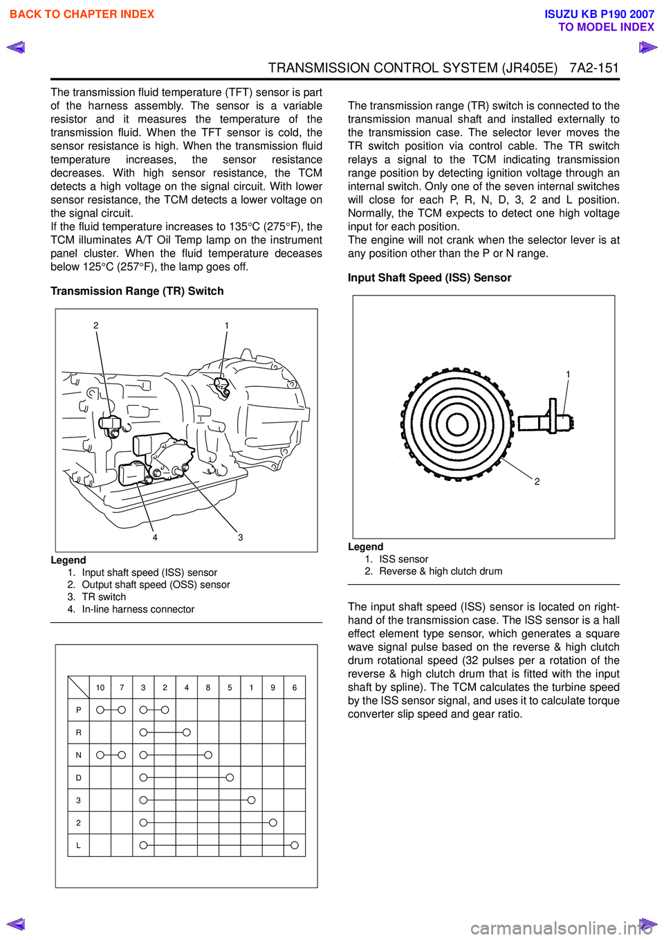
Transmission Range (TR) Switch
Legend 1. Input shaft speed (ISS) sensor
2. Output shaft speed (OSS) sensor
3. TR switch
4. In-line harness connector
The transmission range (TR) switch is connected to the
transmission manual shaft and installed externally to
the transmission case. The selector lever moves the
TR switch position via control cable. The TR switch
relays a signal to the TCM indicating transmission
range position by detecting ignition voltage through an
internal switch. Only one of the seven internal switches
will close for each P, R, N, D, 3, 2 and L position.
Normally, the TCM expects to detect one high voltage
input for each position.
The engine will not crank when the selector lever is at
any position other than the P or N range.
Input Shaft Speed (ISS) Sensor
Legend 1. ISS sensor
2. Reverse & high clutch drum
The input shaft speed (ISS) sensor is located on right-
hand of the transmission case. The ISS sensor is a hall
effect element type sensor, which generates a square
wave signal pulse based on the reverse & high clutch
drum rotational speed (32 pulses per a rotation of the
reverse & high clutch drum that is fitted with the input
shaft by spline). The TCM calculates the turbine speed
by the ISS sensor signal, and uses it to calculate torque
converter slip speed and gear ratio.
3
1
24
P
R
N
D
3
2
L
10732485196
1
2
BACK TO CHAPTER INDEX
TO MODEL INDEX
ISUZU KB P190 2007
Page 4436 of 6020
7A2-152 TRANSMISSION CONTROL SYSTEM (JR405E)
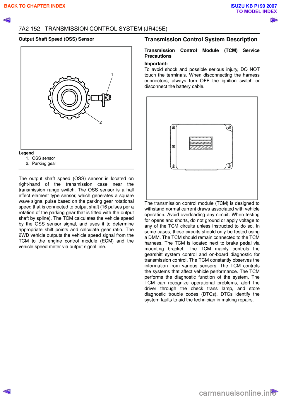
Output Shaft Speed (OSS) Sensor
Legend1. OSS sensor
2. Parking gear
The output shaft speed (OSS) sensor is located on
right-hand of the transmission case near the
transmission range switch. The OSS sensor is a hall
effect element type sensor, which generates a square
wave signal pulse based on the parking gear rotational
speed that is connected to output shaft (16 pulses per a
rotation of the parking gear that is fitted with the output
shaft by spline). The TCM calculates the vehicle speed
by the OSS sensor signal, and uses it to determine
appropriate shift points and calculate gear ratio. The
2WD vehicle outputs the vehicle speed signal from the
TCM to the engine control module (ECM) and the
vehicle speed meter via output signal line.
Transmission Control System Description
Transmission Control Module (TCM) Service
Precautions
Important:
To avoid shock and possible serious injury, DO NOT
touch the terminals. When disconnecting the harness
connectors, always turn OFF the ignition switch or
disconnect the battery cable.
The transmission control module (TCM) is designed to
withstand normal current draws associated with vehicle
operation. Avoid overloading any circuit. When testing
for opens and shorts, do not ground or apply voltage to
any of the TCM circuits unless instructed to do so. In
some cases, these circuits should only be tested using
a DMM. The TCM should remain connected to the TCM
harness. The TCM is located next to brake pedal via
mounting bracket. The TCM mainly controls the
gearshift system control and on-board diagnostic for
transmission control. The TCM constantly observes the
information from various sensors. The TCM controls
the systems that affect vehicle performance. The TCM
performs the diagnostic function of the system. The
TCM can recognize operational problems, alert the
driver through the check trans lamp, and store
diagnostic trouble codes (DTCs). DTCs identify the
system faults to aid the technician in making repairs.
1
2
BACK TO CHAPTER INDEX
TO MODEL INDEX
ISUZU KB P190 2007
Page 4460 of 6020
7A3-6 ON-VEHICLE SERVICE (JR405E)
INHIBITOR SWITCH
The inhibitor switch is attached to the right side of the
transmission.
Inspect
1. Block the wheels.
2. Disconnect the negative battery cable.
3. Disconnect the harness connectors.
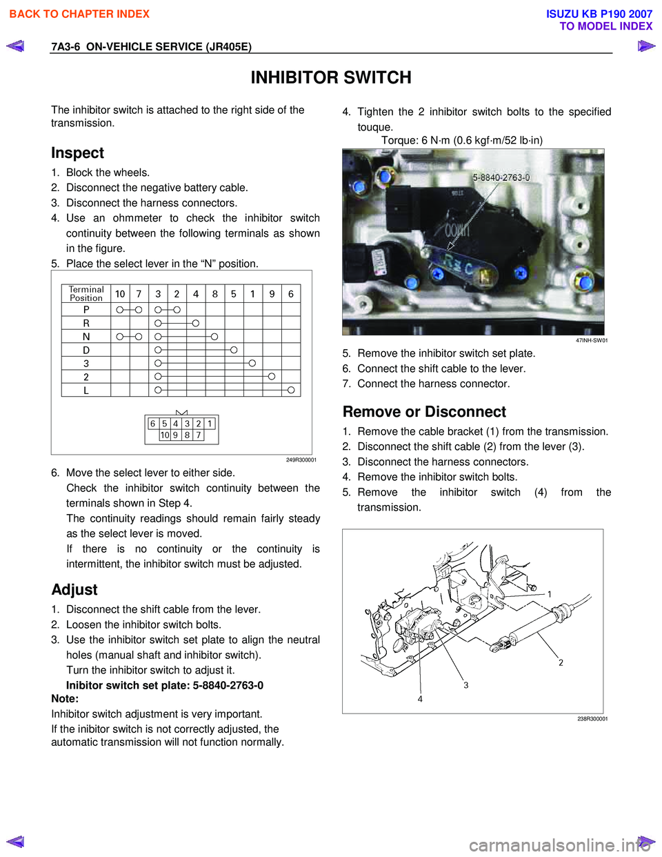
4. Use an ohmmeter to check the inhibitor switch continuity between the following terminals as shown
in the figure.
5. Place the select lever in the “N” position.
249R300001
6. Move the select lever to either side.
Check the inhibitor switch continuity between the terminals shown in Step 4.
The continuity readings should remain fairly stead
y
as the select lever is moved.
If there is no continuity or the continuity is intermittent, the inhibitor switch must be adjusted.
Adjust
1. Disconnect the shift cable from the lever.
2. Loosen the inhibitor switch bolts.
3. Use the inhibitor switch set plate to align the neutral holes (manual shaft and inhibitor switch).
Turn the inhibitor switch to adjust it.
Inibitor switch set plate: 5-8840-2763-0
Note:
Inhibitor switch adjustment is very important.
If the inibitor switch is not correctly adjusted, the
automatic transmission will not function normally.
4. Tighten the 2 inhibitor switch bolts to the specified
touque.
Torque: 6 N·m (0.6 kgf·m/52 lb·in)
47INH-SW 01
5. Remove the inhibitor switch set plate.
6. Connect the shift cable to the lever.
7. Connect the harness connector.
Remove or Disconnect
1. Remove the cable bracket (1) from the transmission.
2. Disconnect the shift cable (2) from the lever (3).
3. Disconnect the harness connectors.
4. Remove the inhibitor switch bolts.
5. Remove the inhibitor switch (4) from the transmission.
238R300001
BACK TO CHAPTER INDEX
TO MODEL INDEX
ISUZU KB P190 2007
Page 4461 of 6020
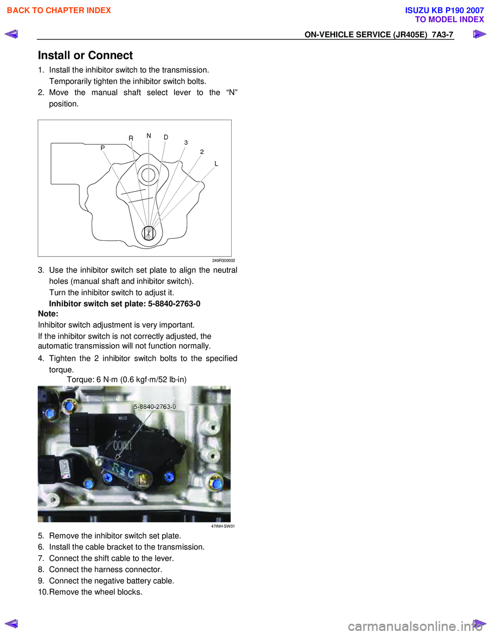
ON-VEHICLE SERVICE (JR405E) 7A3-7
Install or Connect
1. Install the inhibitor switch to the transmission.
Temporarily tighten the inhibitor switch bolts.
2. Move the manual shaft select lever to the “N” position.
249R300002
3. Use the inhibitor switch set plate to align the neutral
holes (manual shaft and inhibitor switch).
Turn the inhibitor switch to adjust it.
Inhibitor switch set plate: 5-8840-2763-0
Note:
Inhibitor switch adjustment is very important.
If the inhibitor switch is not correctly adjusted, the
automatic transmission will not function normally.
4. Tighten the 2 inhibitor switch bolts to the specified torque.
Torque: 6 N·m (0.6 kgf·m/52 lb·in)
47INH-SW 01
5. Remove the inhibitor switch set plate.
6. Install the cable bracket to the transmission.
7. Connect the shift cable to the lever.
8. Connect the harness connector.
9. Connect the negative battery cable.
10. Remove the wheel blocks.
BACK TO CHAPTER INDEX
TO MODEL INDEX
ISUZU KB P190 2007
Page 4463 of 6020
ON-VEHICLE SERVICE (JR405E) 7A3-9
TURBINE SENSOR
The turbine sensor is attached to the right side of the
transmission.
Inspect
1. During driving at a speed of 20km/h (12mph) with “L” range in low gear, measure the voltage between the
TCM connector terminals (B3) and (B5) with a digital
voltmeter.
Standard voltage : approx. 7V (AC range)
2. If the voltage is outside of the standard value, check the turbine sensor pole piece for presence of foreign
materials and the turbine sensor cable for a short o
r
open circuit.
If the result of the inspection is abnormal, replace the turbine sensor.
Torque: 6 N·m (0.6 kgf·m/52 lb·in)
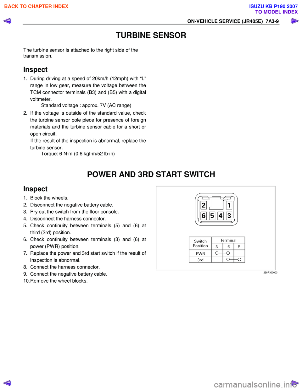
POWER AND 3RD START SWITCH
Inspect
1. Block the wheels.
2. Disconnect the negative battery cable.
3. Pry out the switch from the floor console.
4. Disconnect the harness connector.
5. Check continuity between terminals (5) and (6) at third (3rd) position.
6. Check continuity between terminals (3) and (6) at power (PW R) position.
7. Replace the power and 3rd start switch if the result o
f
inspection is abnormal.
8. Connect the harness connector.
9. Connect the negative battery cable.
10. Remove the wheel blocks.
238R300003
BACK TO CHAPTER INDEX
TO MODEL INDEX
ISUZU KB P190 2007
Page 4465 of 6020
ON-VEHICLE SERVICE (JR405E) 7A3-11
Remove or Disconnect
1. Block the wheels.
2. Disconnect the negative battery cable.
3. Remove the rear console and the front console.
4. Remove the 2 screws fixing the select lever knob.
5. Remove the knob together with the knob button and spring from the lever.
6. Turn the sleeve counterclockwise to remove it. Make a note of the number of turns required to free
the sleeve.
7. Remove the harness connectors from the base plate.
8. Remove the upper housing (held in place by 4 latched fasteners).
9. Remove the lamp assembly by turning it counterclockwise.
10. Remove the spring plate.
11. Remove the grooved pin.
12. Disconnect the shift cable from the select lever.
13. Remove the lever assembly by pressing the rod down (lever in N position).
14. Remove the harness connectors from the shift lock unit, then remove the shift lock unit.
15. Remove the interlock controller.
16. If the replacement of shift lock release button o
r
shift lock button spring is required, remove the
position indicator housing, the shift lock button
spring and shift lock release button can be
removed.
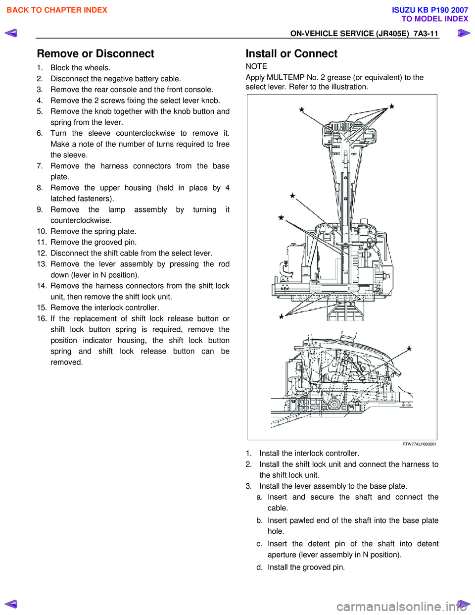
Install or Connect
NOTE
Apply MULTEMP No. 2 grease (or equivalent) to the
select lever. Refer to the illustration.
RTW 77ALH000201
1. Install the interlock controller.
2. Install the shift lock unit and connect the harness to the shift lock unit.
3. Install the lever assembly to the base plate. a. Insert and secure the shaft and connect the cable.
b. Insert pawled end of the shaft into the base plate hole.
c. Insert the detent pin of the shaft into detent aperture (lever assembly in N position).
d. Install the grooved pin.
BACK TO CHAPTER INDEX
TO MODEL INDEX
ISUZU KB P190 2007
Page 4466 of 6020
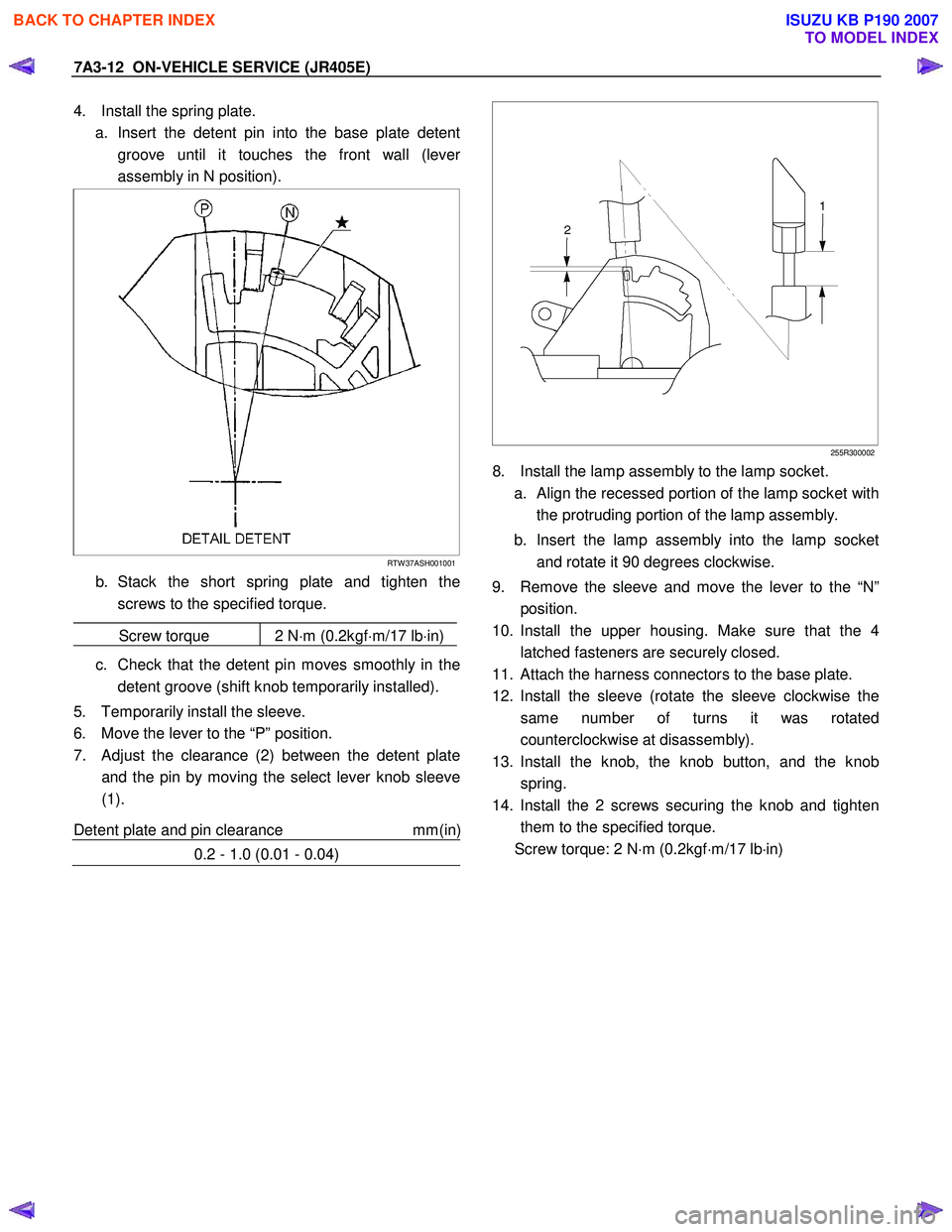
7A3-12 ON-VEHICLE SERVICE (JR405E)
4. Install the spring plate.
a. Insert the detent pin into the base plate detent groove until it touches the front wall (leve
r
assembly in N position).
RTW 37ASH001001
b. Stack the short spring plate and tighten thescrews to the specified torque.
Screw torque 2 N ⋅m (0.2kgf ⋅m/17 lb ⋅in)
c. Check that the detent pin moves smoothly in the
detent groove (shift knob temporarily installed).
5. Temporarily install the sleeve.
6. Move the lever to the “P” position.
7. Adjust the clearance (2) between the detent plate and the pin by moving the select lever knob sleeve
(1).
Detent plate and pin clearance mm(in
)
0.2 - 1.0 (0.01 - 0.04)
255R300002
8. Install the lamp assembly to the lamp socket.
a.
Align the recessed portion of the lamp socket with
the protruding portion of the lamp assembly.
b. Insert the lamp assembly into the lamp socket and rotate it 90 degrees clockwise.
9. Remove the sleeve and move the lever to the “N” position.
10. Install the upper housing. Make sure that the 4 latched fasteners are securely closed.
11. Attach the harness connectors to the base plate.
12. Install the sleeve (rotate the sleeve clockwise the same number of turns it was rotated
counterclockwise at disassembly).
13. Install the knob, the knob button, and the knob spring.
14. Install the 2 screws securing the knob and tighten them to the specified torque.
Screw torque: 2 N ⋅m (0.2kgf ⋅m/17 lb ⋅in)
BACK TO CHAPTER INDEX
TO MODEL INDEX
ISUZU KB P190 2007