Page 4500 of 6020
UNIT REPAIR (JR405E) 7A4-23
CONTROL VALVE LOWER BODY
10CV11
Legend
1. Retainer plate, spring, and steel ball
2. Retainer plate, plug, spring, and pressure regulator valve
3. Retainer plate, spring, and high clutch accumulator
4. Retainer plate, plug, low and reverse brake fail valve A, and spring
5. Retainer plate, plug, spring, and fail valve
6. Retainer plate, plug, low and reverse brake amp valve, and spring
7. Oil pressure switch
8. Oil filter
9. Solenoid
10. Line pressure solenoid
11. Lock-up solenoid
12. Harness bracket
13. Solenoid fixing plate
14. Harness assembly
15. Retainer plate, plug, spring, and 2-4 brake fail valve A
16. Retainer plate, plug, spring, and low clutch amp valve B
17. Retainer plate, spring, and torque converter relief valve
18. Oil strainer
19. Control valve lower body
20. Retainer plate, spring, and 2-4 brake solenoid accumulator
21. Oil pressure switch
BACK TO CHAPTER INDEX
TO MODEL INDEX
ISUZU KB P190 2007
Page 4504 of 6020

UNIT REPAIR (JR405E) 7A4-27
Spring specifications
No. Valve nomenclature Free length
(mm / in) Outside
diameter
(mm / in) Linear
diameter
(mm / in) Number of
coils
14 Pressure relief 49.0 / 1.929 7.6 / 0.299 1.1 / 0.043 17.3
15 Pressure regulator 30.5 / 1.201 14.0 / 0.551 1.4 / 0.055 5.7
16 Low and reverse brake fail (A) 22.0 / 0.866 7.0 / 0.276 0.6 / 0.024 10.0
17 Fail 23.0 / 0.906 11.0 / 0.433 0.5 / 0.020 13.2
18 Low and reverse brake amp 19.5 / 0.768 7.9 / 0.311 0.5 / 0.020 6.9
19 2 – 4 brake fail (A) 24.8 / 0.976 8.5 / 0.335 0.9 / 0.035 7.8
20 Low clutch amp (B) 26.0 / 1.024 11.0 / 0.433 0.5 / 0.020 6.9
21
Torque converter relief More than 47.2
/ 1.858 9.2 / 0.362 1.6 / 0.063 20.2
22 2 – 4 brake solenoid accumulator 31.4 / 1.236 9.8 / 0.386 1.3 / 0.051 9.3
23 High clutch accumulator
51.0 / 2.008 6.5 / 0.256 0.8 / 0.031 23.5
Oil pressure switch
Apply compressed air (390 kPa/4.0 kgf/cm2/57 psi) to the oil
pressure switch to check the oil pressure switch continuity
between the connector and screw.
244L300011
Oil temperature sensor (harness assembly)
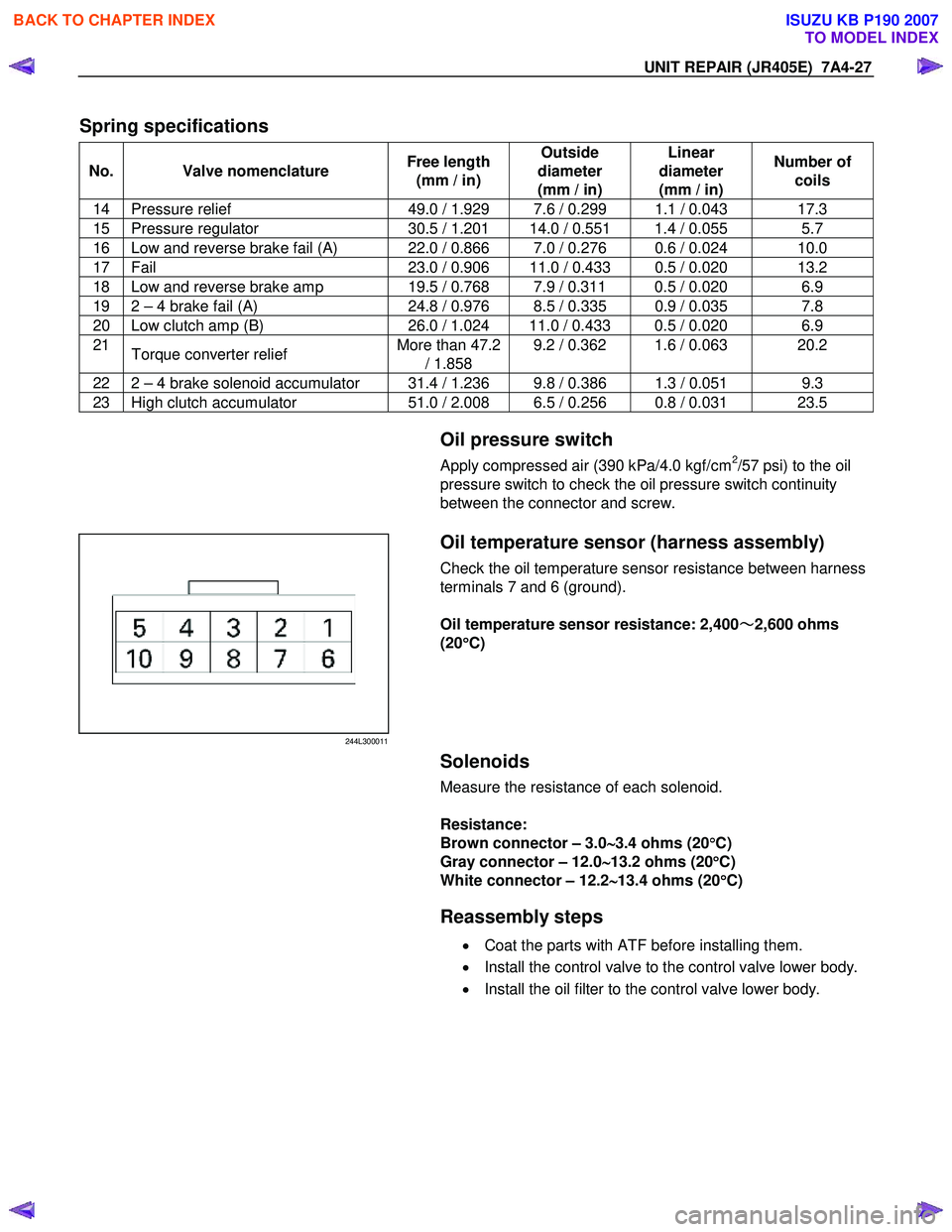
Check the oil temperature sensor resistance between harness
terminals 7 and 6 (ground).
Oil temperature sensor resistance: 2,400 ~
~~
~
2,600 ohms
(20 °
°°
°
C)
Solenoids
Measure the resistance of each solenoid.
Resistance:
Brown connector – 3.0 ∼
∼∼
∼
3.4 ohms (20 °
°°
°
C)
Gray connector – 12.0 ∼
∼∼
∼
13.2 ohms (20 °
°°
°
C)
White connector – 12.2 ∼
∼∼
∼
13.4 ohms (20 °
°°
°
C)
Reassembly steps
• Coat the parts with ATF before installing them.
• Install the control valve to the control valve lower body.
• Install the oil filter to the control valve lower body.
BACK TO CHAPTER INDEX
TO MODEL INDEX
ISUZU KB P190 2007
Page 4532 of 6020
UNIT REPAIR (JR405E) 7A4-55
01L&R-CS05
Legend
1. Seal ring
2. Low one-way clutch inner race
3. Return spring
4. Low and reverse brake piston
5. Seal ring
6. Lip seal
7. Transmission case
8. Snap ring
9. Retaining plate
10. Driven plate
11. Drive plate
12. Dish plate
04CASE-AY52
Disassembly steps
1. Harness assembly
Remove the fixing bolt and the harness assembly.
BACK TO CHAPTER INDEX
TO MODEL INDEX
ISUZU KB P190 2007
Page 4536 of 6020
UNIT REPAIR (JR405E) 7A4-59
18CASE-AY43
•
Use a pin punch to drive the manual plate spring pin into
place.
21CASE-AY48
3. Detent spring
• Install the detent spring and tighten the fixing bolt to the
specified torque.
Torque: 7 N ⋅
⋅⋅
⋅
m (0.7 kgf ⋅
⋅⋅
⋅
m/61 Ib ⋅
⋅⋅
⋅
in)
23CASE-AY53
4. Harness assembly
• Apply automatic transmission fluid to the new O-ring and
install them to the harness assembly.
• Install the harness assembly to the transmission case.
Tighten the fixing bolt to the specified torque.
Torque: 6 N ⋅
⋅⋅
⋅
m (0.6 kgf ⋅
⋅⋅
⋅
m/52 Ib ⋅
⋅⋅
⋅
in)
24ASSY003
5. Low one-way clutch inner race
• Install new seal rings to the low one-way clutch inne
r
race.
25ASSY126
•
Measure the gap between the seal ring and the ring
groove.
If the measured valve is outside the specified range the
low one-way clutch inner race must be replaced.
Sealing ring and ring groove gap:
0.10~0.25 mm (0.0039~0.0098 in)
BACK TO CHAPTER INDEX
TO MODEL INDEX
ISUZU KB P190 2007
Page 4557 of 6020
7A4-80 UNIT REPAIR (JR405E)
43ASSY119
20.Control valve assembly
•
Align the manual valve and the manual plate of the
transmission case.
• Install the control valve assembly and tighten the 12
fixing bolts to the specified torque.
Number of bolts Length Color
10 (A) 40 mm (1.57 in) Gold
2 (B) 30 mm (1.18 in) Gold
44ASSY121
Torque: 8 N ⋅
⋅⋅
⋅
m (0.8 kgf ⋅
⋅⋅
⋅
m/69 Ib ⋅
⋅⋅
⋅
in)
45CV29
•
Connect the harness assembly and control valve
assembly connectors.
BACK TO CHAPTER INDEX
TO MODEL INDEX
ISUZU KB P190 2007
Page 4572 of 6020
7B-8 MSG MODEL
Exhaust Pipe
1. Remove the exhaust pipe bracket from the transmission
case.
2. Remove the exhaust pipe.
Rear Propeller Shaft (Dual Shaft Type)
1. Apply setting marks to the 2nd propeller shaft flange yoke.
This will prevent mispositioning during the installation procedure.
2. Remove the 2nd propeller shaft flange yoke nuts at the drive pinion side
1.
3. Remove the center bearing retainer bolts
2 .
4. Remove the 1st propeller shaft with the center bearing and the 2nd propeller shaft.
Pull the 1st propeller shaft toward the rear of the vehicle until the spline yoke is free of the transmission main shaft.
Harness Connector
Disconnect the back up light switch connector and the
speedometer sensor connector.
Slave Cylinder
Remove the slave cylinder from the transmission case.
BACK TO CHAPTER INDEX
TO MODEL INDEX
ISUZU KB P190 2007
Page 4577 of 6020

MSG MODEL 7B-13
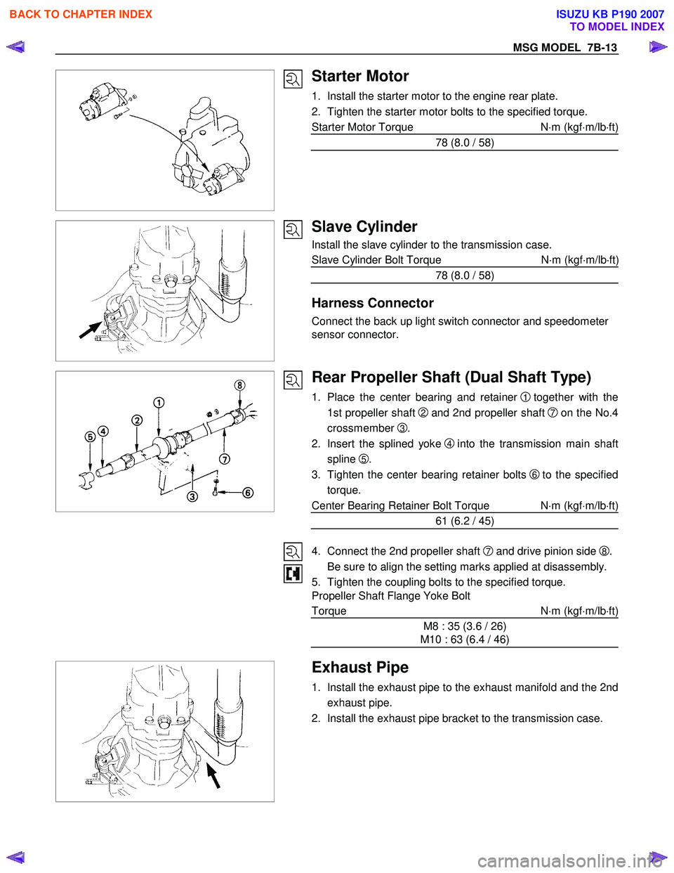
Starter Motor
1. Install the starter motor to the engine rear plate.
2. Tighten the starter motor bolts to the specified torque.
Starter Motor Torque N⋅m (kgf ⋅m/lb ⋅ft)
78 (8.0 / 58)
Slave Cylinder
Install the slave cylinder to the transmission case.
Slave Cylinder Bolt Torque N ⋅m (kgf ⋅m/lb ⋅ft
)
78 (8.0 / 58)
Harness Connector
Connect the back up light switch connector and speedometer
sensor connector.
Rear Propeller Shaft (Dual Shaft Type)
1. Place the center bearing and retainer 1 together with the
1st propeller shaft
2 and 2nd propeller shaft 7on the No.4
crossmember
3.
2. Insert the splined yoke
4 into the transmission main shaft
spline
5.
3. Tighten the center bearing retainer bolts
6 to the specified
torque.
Center Bearing Retainer Bolt Torque N ⋅m (kgf ⋅m/lb ⋅ft)
61 (6.2 / 45)
4. Connect the 2nd propeller shaft
7 and drive pinion side 8.
Be sure to align the setting marks applied at disassembly.
5. Tighten the coupling bolts to the specified torque.
Propeller Shaft Flange Yoke Bolt
Torque N ⋅m (kgf ⋅m/lb ⋅ft)
M8 : 35 (3.6 / 26)
M10 : 63 (6.4 / 46)
Exhaust Pipe
1. Install the exhaust pipe to the exhaust manifold and the 2nd
exhaust pipe.
2. Install the exhaust pipe bracket to the transmission case.
BACK TO CHAPTER INDEX
TO MODEL INDEX
ISUZU KB P190 2007
Page 4615 of 6020
MANUAL TRANSMISSION 7B1-9
6. Remove the gear control lever.
7. Raise and support the vehicle with suitable stands.
8. Remove the rear propeller shaft.
NOTE: Apply alignment marks on the flange at the
differential side.
401RS023
9. Loosen the front exhaust pipe fixing nuts at the engine side but do not remove them. (Diesel engine
only)
RTW 67BSH000101
10. Disconnect the harness connectors and clips on the
transmission.
• Neutral Switch
• Back up Switch
• Car Speed Sensor
11. Remove the fuel pipe bracket with pipes from the transmission.
Diesel engine
220R300012
Legend
(1) Bolt
(2) Nut
(3) Fuel Pipe Assembly
C24SE
Scan-1
BACK TO CHAPTER INDEX
TO MODEL INDEX
ISUZU KB P190 2007