2007 ISUZU KB P190 Harness
[x] Cancel search: HarnessPage 4371 of 6020
TRANSMISSION CONTROL SYSTEM (JR405E) 7A2-87
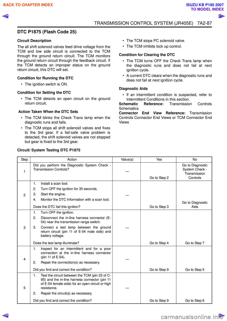
DTC P1875 (Flash Code 25)
Circuit Description
The all shift solenoid valves feed drive voltage from the
TCM and low side circuit is connected to the TCM
through the ground return circuit. The TCM monitors
the ground return circuit through the feedback circuit. If
the TCM detects an improper status on the ground
return circuit, this DTC will set.
Condition for Running the DTC • The ignition switch is ON.
Condition for Setting the DTC • The TCM detects an open circuit on the ground return circuit.
Action Taken When the DTC Sets • The TCM blinks the Check Trans lamp when the diagnostic runs and fails.
• The TCM stops all shift solenoid valves and fixes to the 3rd gear. If a fail-safe valve problem is
detected, the shift solenoid valves are not stopped
but gear is fixed to the 3rd gear. • The TCM stops PC solenoid valve.
• The TCM inhibits lock up control.
Condition for Clearing the DTC • The TCM turns OFF the Check Trans lamp when the diagnostic runs and does not fail at next
ignition cycle.
• A current DTC clears when the diagnostic runs and does not fail at next ignition cycle.
Diagnostic Aids • If an intermittent condition is suspected, refer to Intermittent Conditions in this section.
Schematic Reference: Transmission Controls
Schematics
Connector End View Reference: Transmission
Controls Connector End Views or TCM Connector End
Views
Circuit/ System Testing DTC P1875
Step Action Value(s)Yes No
1 Did you perform the Diagnostic System Check -
Transmission Controls? —
Go to Step 2 Go to Diagnostic
System Check -
Transmission Controls
2 1. Install a scan tool.
2. Turn OFF the ignition for 30 seconds.
3. Start the engine.
4. Monitor the DTC Information with a scan tool.
Does the DTC fail this ignition? —
Go to Step 3 Go to Diagnostic
Aids
3 1. Turn OFF the ignition.
2. Disconnect the in-line harness connector (E- 54) near the transmission range switch.
3. Connect a test lamp between the ground return circuit (pin 11 of E-54 male side) and
battery voltage.
Does the test lamp illuminate? —
Go to Step 4 Go to Step 7
4 1. Inspect for an intermittent and for a poor
connection at the in-line harness connector
(pin 11 of E-54).
2. Repair the connection(s) as necessary.
Did you find and correct the condition? —
Go to Step 9 Go to Step 5
5 1. Test the circuit between the TCM (pin 22 of C-
95) and the in-line harness connector (pin 11
of E-54 female side) for an open circuit or high
resistance.
2. Repair the circuit(s) as necessary.
Did you find and correct the condition? —
Go to Step 9 Go to Step 6
BACK TO CHAPTER INDEX
TO MODEL INDEX
ISUZU KB P190 2007
Page 4372 of 6020

7A2-88 TRANSMISSION CONTROL SYSTEM (JR405E)
61. Turn OFF the ignition.
2. Disconnect the TCM harness connector.
3. Inspect for an intermittent and for a poor connection at the harness connector of the
TCM (pin 22 of C-95).
4. Repair the connection(s) as necessary.
Did you find and correct the condition? —
Go to Step 9 Go to Step 8
7 1. Remove the transmission oil pan. Refer to
repair instructions (On-Vehicle Service).
2. Inspect for an intermittent and for a poor connection at the ground terminal or in-line
harness connector. Clean or tighten grounds
as necessary.
3. Repair the open circuit or high between the ground terminal and the in-line harness
connector (pin 11 of E-54 male side).
Did you complete the repair? —
Go to Step 9 —
8 Important:
Replacement TCM must be
programmed.
Replace the TCM. Refer to TCM Replacement.
Did you complete the replacement? —
Go to Step 9 —
9 1. Reconnect all previously disconnected
components or harness connector(s).
2. Clear the DTCs with a scan tool.
3. Turn OFF the ignition for 30 seconds.
4. Start the engine.
Did the DTC fail this ignition? —
Go to Step 3 Go to Step 10
10 Observe the DTC Information with a scan tool.
Are there any DTCs that you have not diagnosed? —
Go to DTC List System OK
Step
Action Value(s)Yes No
BACK TO CHAPTER INDEX
TO MODEL INDEX
ISUZU KB P190 2007
Page 4374 of 6020
7A2-90 TRANSMISSION CONTROL SYSTEM (JR405E)
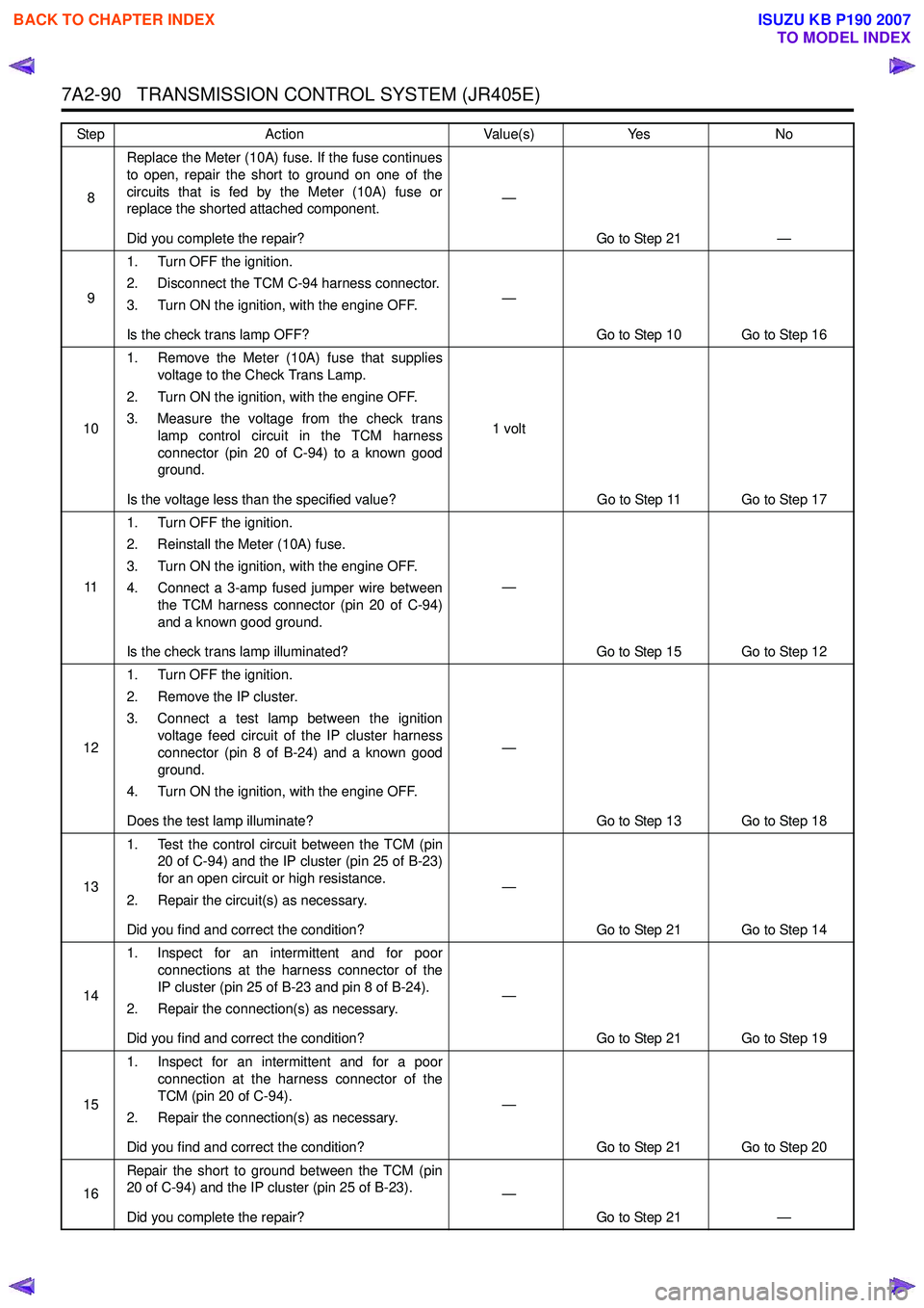
8Replace the Meter (10A) fuse. If the fuse continues
to open, repair the short to ground on one of the
circuits that is fed by the Meter (10A) fuse or
replace the shorted attached component.
Did you complete the repair? —
Go to Step 21 —
9 1. Turn OFF the ignition.
2. Disconnect the TCM C-94 harness connector.
3. Turn ON the ignition, with the engine OFF.
Is the check trans lamp OFF? —
Go to Step 10 Go to Step 16
10 1. Remove the Meter (10A) fuse that supplies
voltage to the Check Trans Lamp.
2. Turn ON the ignition, with the engine OFF.
3. Measure the voltage from the check trans lamp control circuit in the TCM harness
connector (pin 20 of C-94) to a known good
ground.
Is the voltage less than the specified value? 1 volt
Go to Step 11 Go to Step 17
11 1. Turn OFF the ignition.
2. Reinstall the Meter (10A) fuse.
3. Turn ON the ignition, with the engine OFF.
4. Connect a 3-amp fused jumper wire between the TCM harness connector (pin 20 of C-94)
and a known good ground.
Is the check trans lamp illuminated? —
Go to Step 15 Go to Step 12
12 1. Turn OFF the ignition.
2. Remove the IP cluster.
3. Connect a test lamp between the ignition voltage feed circuit of the IP cluster harness
connector (pin 8 of B-24) and a known good
ground.
4. Turn ON the ignition, with the engine OFF.
Does the test lamp illuminate? —
Go to Step 13 Go to Step 18
13 1. Test the control circuit between the TCM (pin
20 of C-94) and the IP cluster (pin 25 of B-23)
for an open circuit or high resistance.
2. Repair the circuit(s) as necessary.
Did you find and correct the condition? —
Go to Step 21 Go to Step 14
14 1. Inspect for an intermittent and for poor
connections at the harness connector of the
IP cluster (pin 25 of B-23 and pin 8 of B-24).
2. Repair the connection(s) as necessary.
Did you find and correct the condition? —
Go to Step 21 Go to Step 19
15 1. Inspect for an intermittent and for a poor
connection at the harness connector of the
TCM (pin 20 of C-94).
2. Repair the connection(s) as necessary.
Did you find and correct the condition? —
Go to Step 21 Go to Step 20
16 Repair the short to ground between the TCM (pin
20 of C-94) and the IP cluster (pin 25 of B-23).
Did you complete the repair? —
Go to Step 21 —
Step
Action Value(s)Yes No
BACK TO CHAPTER INDEX
TO MODEL INDEX
ISUZU KB P190 2007
Page 4375 of 6020
TRANSMISSION CONTROL SYSTEM (JR405E) 7A2-91
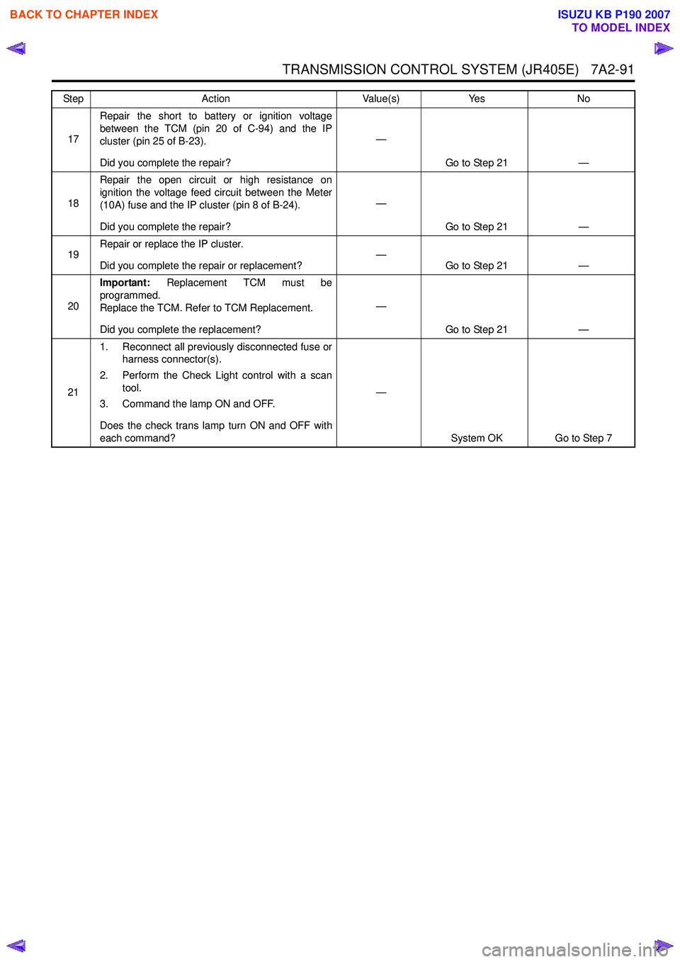
17Repair the short to battery or ignition voltage
between the TCM (pin 20 of C-94) and the IP
cluster (pin 25 of B-23).
Did you complete the repair? —
Go to Step 21 —
18 Repair the open circuit or high resistance on
ignition the voltage feed circuit between the Meter
(10A) fuse and the IP cluster (pin 8 of B-24).
Did you complete the repair? —
Go to Step 21 —
19 Repair or replace the IP cluster.
Did you complete the repair or replacement? —
Go to Step 21 —
20 Important:
Replacement TCM must be
programmed.
Replace the TCM. Refer to TCM Replacement.
Did you complete the replacement? —
Go to Step 21 —
21 1. Reconnect all previously disconnected fuse or
harness connector(s).
2. Perform the Check Light control with a scan tool.
3. Command the lamp ON and OFF.
Does the check trans lamp turn ON and OFF with
each command? —
System OK Go to Step 7
Step
Action Value(s)Yes No
BACK TO CHAPTER INDEX
TO MODEL INDEX
ISUZU KB P190 2007
Page 4376 of 6020
7A2-92 TRANSMISSION CONTROL SYSTEM (JR405E)
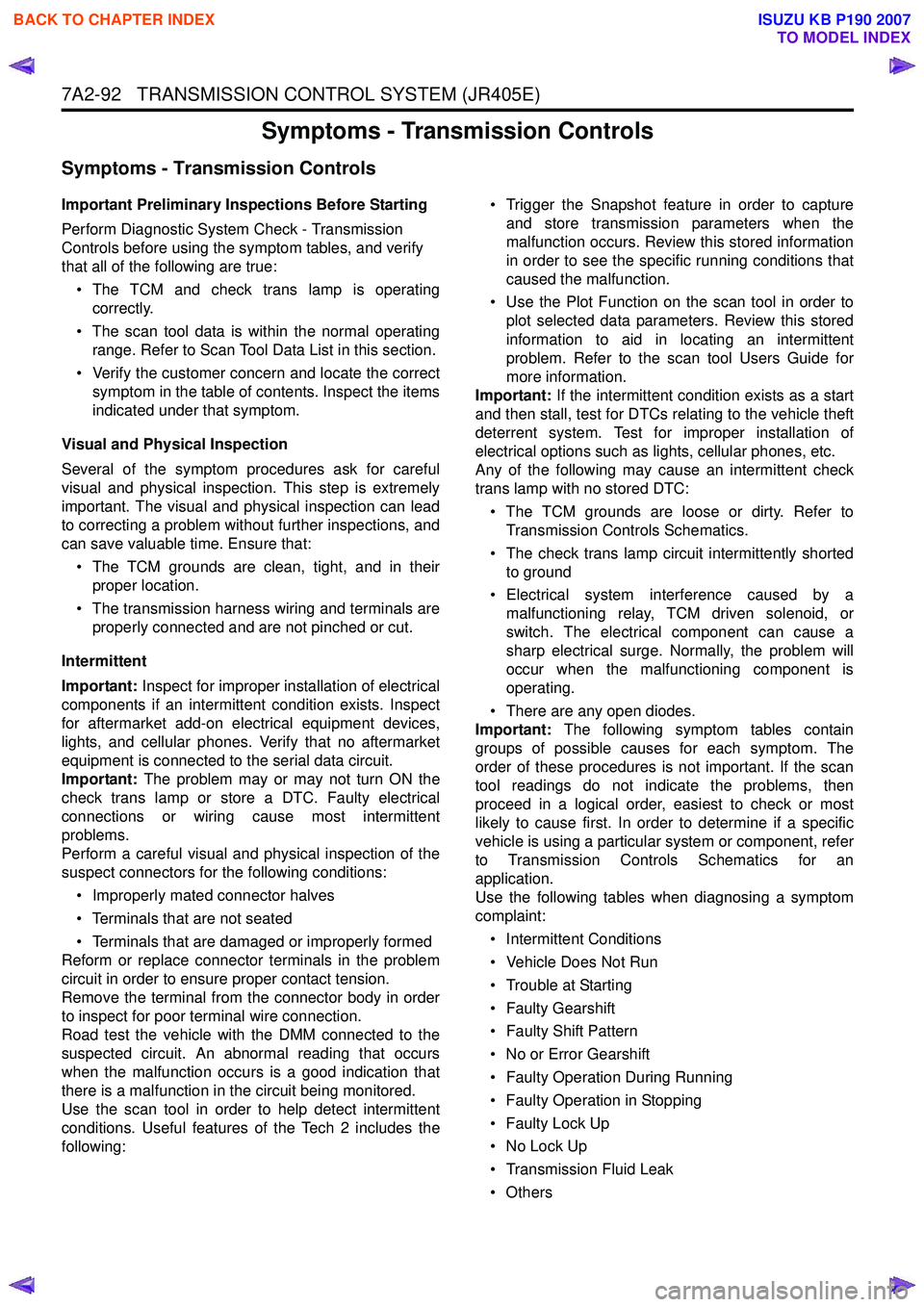
Symptoms - Transmission Controls
Symptoms - Transmission Controls
Important Preliminary Inspections Before Starting
Perform Diagnostic System Check - Transmission
Controls before using the symptom tables, and verify
that all of the following are true:
• The TCM and check trans lamp is operating correctly.
• The scan tool data is within the normal operating range. Refer to Scan Tool Data List in this section.
• Verify the customer concern and locate the correct symptom in the table of contents. Inspect the items
indicated under that symptom.
Visual and Physical Inspection
Several of the symptom procedures ask for careful
visual and physical inspection. This step is extremely
important. The visual and physical inspection can lead
to correcting a problem without further inspections, and
can save valuable time. Ensure that:
• The TCM grounds are clean, tight, and in their proper location.
• The transmission harness wiring and terminals are properly connected and are not pinched or cut.
Intermittent
Important: Inspect for improper installation of electrical
components if an intermittent condition exists. Inspect
for aftermarket add-on electrical equipment devices,
lights, and cellular phones. Verify that no aftermarket
equipment is connected to the serial data circuit.
Important: The problem may or may not turn ON the
check trans lamp or store a DTC. Faulty electrical
connections or wiring cause most intermittent
problems.
Perform a careful visual and physical inspection of the
suspect connectors for the following conditions:
• Improperly mated connector halves
• Terminals that are not seated
• Terminals that are damaged or improperly formed
Reform or replace connector terminals in the problem
circuit in order to ensure proper contact tension.
Remove the terminal from the connector body in order
to inspect for poor terminal wire connection.
Road test the vehicle with the DMM connected to the
suspected circuit. An abnormal reading that occurs
when the malfunction occurs is a good indication that
there is a malfunction in the circuit being monitored.
Use the scan tool in order to help detect intermittent
conditions. Useful features of the Tech 2 includes the
following: • Trigger the Snapshot feature in order to capture
and store transmission parameters when the
malfunction occurs. Review this stored information
in order to see the specific running conditions that
caused the malfunction.
• Use the Plot Function on the scan tool in order to plot selected data parameters. Review this stored
information to aid in locating an intermittent
problem. Refer to the scan tool Users Guide for
more information.
Important: If the intermittent condition exists as a start
and then stall, test for DTCs relating to the vehicle theft
deterrent system. Test for improper installation of
electrical options such as lights, cellular phones, etc.
Any of the following may cause an intermittent check
trans lamp with no stored DTC:
• The TCM grounds are loose or dirty. Refer to Transmission Controls Schematics.
• The check trans lamp circuit intermittently shorted to ground
• Electrical system interference caused by a malfunctioning relay, TCM driven solenoid, or
switch. The electrical component can cause a
sharp electrical surge. Normally, the problem will
occur when the malfunctioning component is
operating.
• There are any open diodes.
Important: The following symptom tables contain
groups of possible causes for each symptom. The
order of these procedures is not important. If the scan
tool readings do not indicate the problems, then
proceed in a logical order, easiest to check or most
likely to cause first. In order to determine if a specific
vehicle is using a particular system or component, refer
to Transmission Controls Schematics for an
application.
Use the following tables when diagnosing a symptom
complaint:
• Intermittent Conditions
• Vehicle Does Not Run
• Trouble at Starting
• Faulty Gearshift
• Faulty Shift Pattern
• No or Error Gearshift
• Faulty Operation During Running
• Faulty Operation in Stopping
• Faulty Lock Up
• No Lock Up
• Transmission Fluid Leak
•Others
BACK TO CHAPTER INDEX
TO MODEL INDEX
ISUZU KB P190 2007
Page 4377 of 6020
TRANSMISSION CONTROL SYSTEM (JR405E) 7A2-93
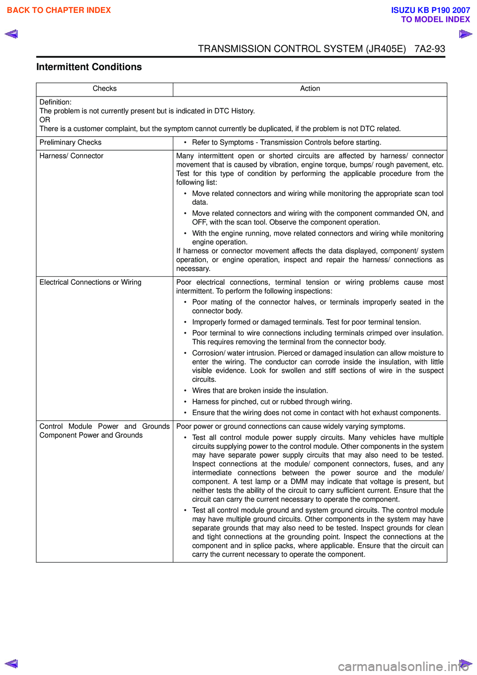
Intermittent Conditions
ChecksAction
Definition:
The problem is not currently present but is indicated in DTC History.
OR
There is a customer complaint, but the symptom cannot currently be duplicated, if the problem is not DTC related.
Preliminary Checks • Refer to Symptoms - Transmission Controls before starting.
Harness/ Connector Many intermittent open or shorted circuits are affected by harness/ connector
movement that is caused by vibration, engine torque, bumps/ rough pavement, etc.
Test for this type of condition by performing the applicable procedure from the
following list:
• Move related connectors and wiring while monitoring the appropriate scan tool data.
• Move related connectors and wiring with the component commanded ON, and OFF, with the scan tool. Observe the component operation.
• With the engine running, move related connectors and wiring while monitoring engine operation.
If harness or connector movement affects the data displayed, component/ system
operation, or engine operation, inspect and repair the harness/ connections as
necessary.
Electrical Connections or Wiring Poor electrical connections, terminal tension or wiring problems cause most intermittent. To perform the following inspections:
• Poor mating of the connector halves, or terminals improperly seated in the connector body.
• Improperly formed or damaged terminals. Test for poor terminal tension.
• Poor terminal to wire connections including terminals crimped over insulation. This requires removing the terminal from the connector body.
• Corrosion/ water intrusion. Pierced or damaged insulation can allow moisture to enter the wiring. The conductor can corrode inside the insulation, with little
visible evidence. Look for swollen and stiff sections of wire in the suspect
circuits.
• Wires that are broken inside the insulation.
• Harness for pinched, cut or rubbed through wiring.
• Ensure that the wiring does not come in contact with hot exhaust components.
Control Module Power and Grounds
Component Power and Grounds Poor power or ground connections can cause widely varying symptoms.
• Test all control module power supply circuits. Many vehicles have multiple circuits supplying power to the control module. Other components in the system
may have separate power supply circuits that may also need to be tested.
Inspect connections at the module/ component connectors, fuses, and any
intermediate connections between the power source and the module/
component. A test lamp or a DMM may indicate that voltage is present, but
neither tests the ability of the circuit to carry sufficient current. Ensure that the
circuit can carry the current necessary to operate the component.
• Test all control module ground and system ground circuits. The control module may have multiple ground circuits. Other components in the system may have
separate grounds that may also need to be tested. Inspect grounds for clean
and tight connections at the grounding point. Inspect the connections at the
component and in splice packs, where applicable. Ensure that the circuit can
carry the current necessary to operate the component.
BACK TO CHAPTER INDEX
TO MODEL INDEX
ISUZU KB P190 2007
Page 4378 of 6020
7A2-94 TRANSMISSION CONTROL SYSTEM (JR405E)
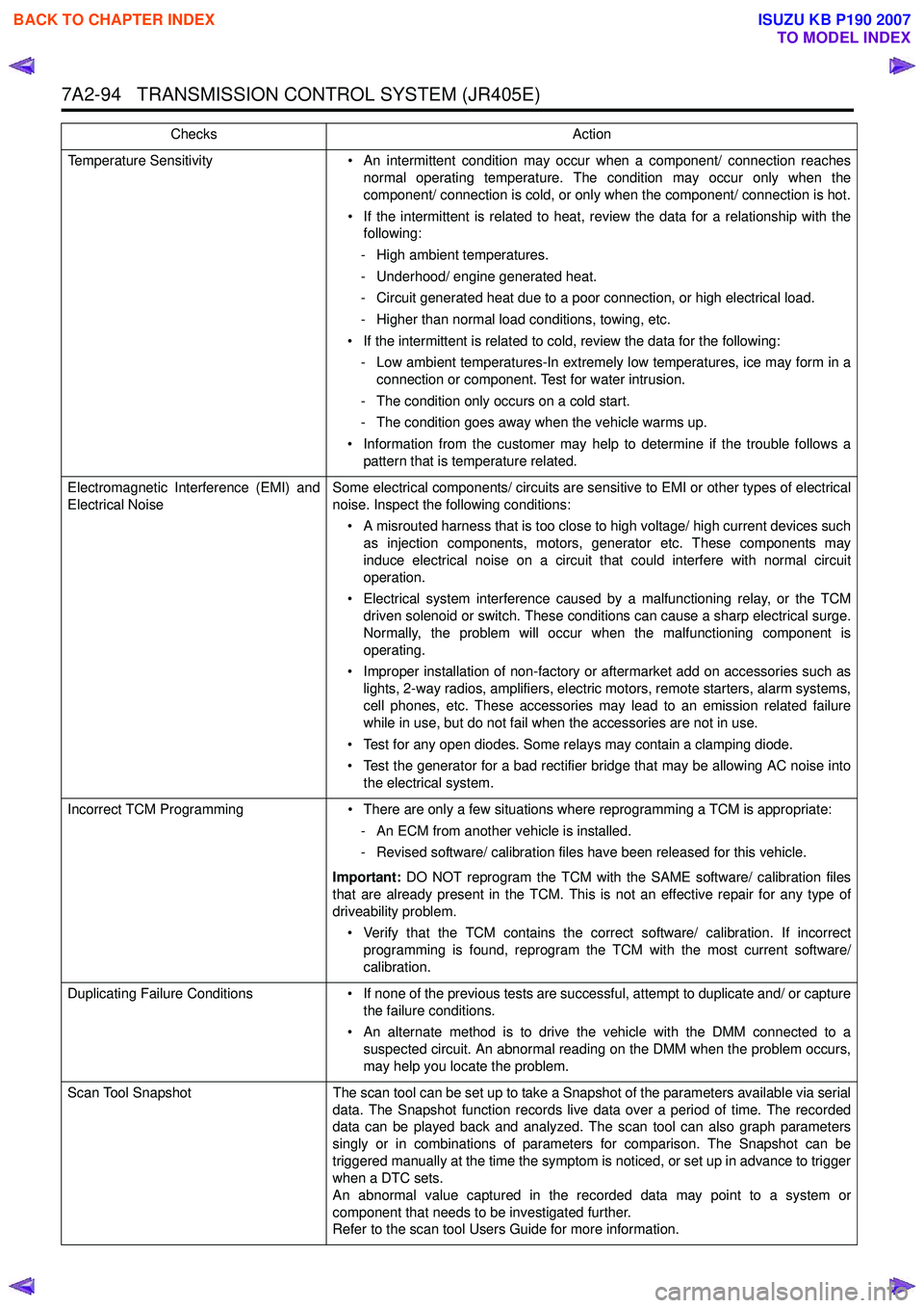
Temperature Sensitivity• An intermittent condition may occur when a component/ connection reaches
normal operating temperature. The condition may occur only when the
component/ connection is cold, or only when the component/ connection is hot.
• If the intermittent is related to heat, review the data for a relationship with the following:
- High ambient temperatures.
- Underhood/ engine generated heat.
- Circuit generated heat due to a poor connection, or high electrical load.
- Higher than normal load conditions, towing, etc.
• If the intermittent is related to cold, review the data for the following: - Low ambient temperatures-In extremely low temperatures, ice may form in a connection or component. Test for water intrusion.
- The condition only occurs on a cold start.
- The condition goes away when the vehicle warms up.
• Information from the customer may help to determine if the trouble follows a pattern that is temperature related.
Electromagnetic Interference (EMI) and
Electrical Noise Some electrical components/ circuits are sensitive to EMI or other types of electrical
noise. Inspect the following conditions:
• A misrouted harness that is too close to high voltage/ high current devices such as injection components, motors, generator etc. These components may
induce electrical noise on a circuit that could interfere with normal circuit
operation.
• Electrical system interference caused by a malfunctioning relay, or the TCM driven solenoid or switch. These conditions can cause a sharp electrical surge.
Normally, the problem will occur when the malfunctioning component is
operating.
• Improper installation of non-factory or aftermarket add on accessories such as lights, 2-way radios, amplifiers, electric motors, remote starters, alarm systems,
cell phones, etc. These accessories may lead to an emission related failure
while in use, but do not fail when the accessories are not in use.
• Test for any open diodes. Some relays may contain a clamping diode.
• Test the generator for a bad rectifier bridge that may be allowing AC noise into the electrical system.
Incorrect TCM Programming • There are only a few situations where reprogramming a TCM is appropriate:
- An ECM from another vehicle is installed.
- Revised software/ calibration files have been released for this vehicle.
Important: DO NOT reprogram the TCM with the SAME software/ calibration files
that are already present in the TCM. This is not an effective repair for any type of
driveability problem.
• Verify that the TCM contains the correct software/ calibration. If incorrect programming is found, reprogram the TCM with the most current software/
calibration.
Duplicating Failure Conditions • If none of the previous tests are successful, attempt to duplicate and/ or capture
the failure conditions.
• An alternate method is to drive the vehicle with the DMM connected to a suspected circuit. An abnormal reading on the DMM when the problem occurs,
may help you locate the problem.
Scan Tool Snapshot The scan tool can be set up to take a Snapshot of the parameters available via serial
data. The Snapshot function records live data over a period of time. The recorded
data can be played back and analyzed. The scan tool can also graph parameters
singly or in combinations of parameters for comparison. The Snapshot can be
triggered manually at the time the symptom is noticed, or set up in advance to trigger
when a DTC sets.
An abnormal value captured in the recorded data may point to a system or
component that needs to be investigated further.
Refer to the scan tool Users Guide for more information.
Checks
Action
BACK TO CHAPTER INDEX
TO MODEL INDEX
ISUZU KB P190 2007
Page 4423 of 6020
TRANSMISSION CONTROL SYSTEM (JR405E) 7A2-139
Repair Instructions
Transmission Controls Module (TCM) Replacement
Description
The following A - C steps provide an overview
procedure to replace and reprogram a TCM. Each A -C
steps is explained further in this section.
A. Replace the old TCM with the new TCM.
B. Program the latest software and calibrations into the
new TCM using the Service Programming System
(SPS) if released. If not released, do not perform this
and skip to Step C.
C. Program the vehicle identification number (VIN) into
the TCM.
A. Removal and Installation
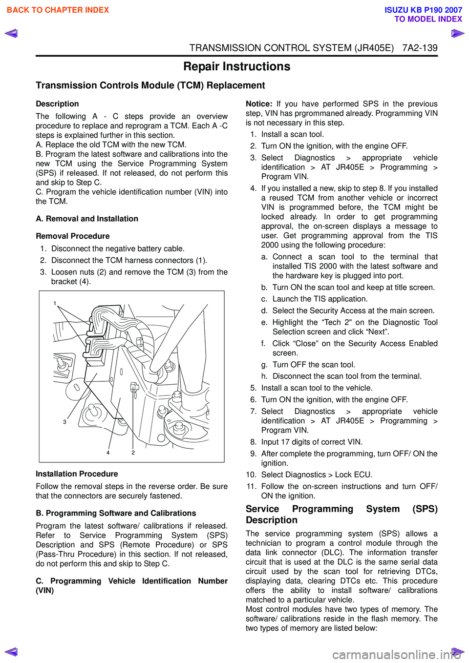
Removal Procedure 1. Disconnect the negative battery cable.
2. Disconnect the TCM harness connectors (1).
3. Loosen nuts (2) and remove the TCM (3) from the bracket (4).
Installation Procedure
Follow the removal steps in the reverse order. Be sure
that the connectors are securely fastened.
B. Programming Software and Calibrations
Program the latest software/ calibrations if released.
Refer to Service Programming System (SPS)
Description and SPS (Remote Procedure) or SPS
(Pass-Thru Procedure) in this section. If not released,
do not perform this and skip to Step C.
C. Programming Vehicle Identification Number
(VIN) Notice:
If you have performed SPS in the previous
step, VIN has prgrommaned already. Programming VIN
is not necessary in this step.
1. Install a scan tool.
2. Turn ON the ignition, with the engine OFF.
3. Select Diagnostics > appropriate vehicle identification > AT JR405E > Programming >
Program VIN.
4. If you installed a new, skip to step 8. If you installed a reused TCM from another vehicle or incorrect
VIN is programmed before, the TCM might be
locked already. In order to get programming
approval, the on-screen displays a message to
user. Get programming approval from the TIS
2000 using the following procedure:
a. Connect a scan tool to the terminal that installed TIS 2000 with the latest software and
the hardware key is plugged into port.
b. Turn ON the scan tool and keep at title screen.
c. Launch the TIS application.
d. Select the Security Access at the main screen.
e. Highlight the “Tech 2" on the Diagnostic Tool Selection screen and click “Next”.
f. Click “Close” on the Security Access Enabled screen.
g. Turn OFF the scan tool.
h. Disconnect the scan tool from the terminal.
5. Install a scan tool to the vehicle.
6. Turn ON the ignition, with the engine OFF.
7. Select Diagnostics > appropriate vehicle identification > AT JR405E > Programming >
Program VIN.
8. Input 17 digits of correct VIN.
9. After complete the programming, turn OFF/ ON the ignition.
10. Select Diagnostics > Lock ECU.
11. Follow the on-screen instructions and turn OFF/ ON the ignition.
Service Programming System (SPS)
Description
The service programming system (SPS) allows a
technician to program a control module through the
data link connector (DLC). The information transfer
circuit that is used at the DLC is the same serial data
circuit used by the scan tool for retrieving DTCs,
displaying data, clearing DTCs etc. This procedure
offers the ability to install software/ calibrations
matched to a particular vehicle.
Most control modules have two types of memory. The
software/ calibrations reside in the flash memory. The
two types of memory are listed below:
1
3 42
BACK TO CHAPTER INDEX
TO MODEL INDEX
ISUZU KB P190 2007