2007 ISUZU KB P190 Harness
[x] Cancel search: HarnessPage 4347 of 6020
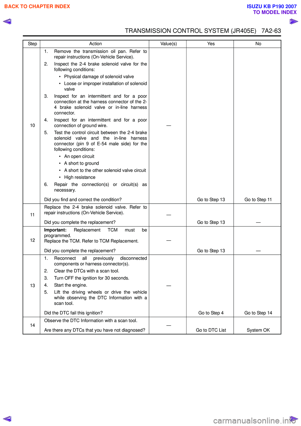
TRANSMISSION CONTROL SYSTEM (JR405E) 7A2-63
101. Remove the transmission oil pan. Refer to
repair instructions (On-Vehicle Service).
2. Inspect the 2-4 brake solenoid valve for the following conditions:
• Physical damage of solenoid valve
• Loose or improper installation of solenoid valve
3. Inspect for an intermittent and for a poor connection at the harness connector of the 2-
4 brake solenoid valve or in-line harness
connector.
4. Inspect for an intermittent and for a poor connection of ground wire.
5. Test the control circuit between the 2-4 brake solenoid valve and the in-line harness
connector (pin 9 of E-54 male side) for the
following conditions:
• An open circuit
• A short to ground
• A short to the other solenoid valve circuit
• High resistance
6. Repair the connection(s) or circuit(s) as necessary.
Did you find and correct the condition? —
Go to Step 13 Go to Step 11
11 Replace the 2-4 brake solenoid valve. Refer to
repair instructions (On-Vehicle Service).
Did you complete the replacement? —
Go to Step 13 —
12 Important:
Replacement TCM must be
programmed.
Replace the TCM. Refer to TCM Replacement.
Did you complete the replacement? —
Go to Step 13 —
13 1. Reconnect all previously disconnected
components or harness connector(s).
2. Clear the DTCs with a scan tool.
3. Turn OFF the ignition for 30 seconds.
4. Start the engine.
5. Lift the driving wheels or drive the vehicle while observing the DTC Information with a
scan tool.
Did the DTC fail this ignition? —
Go to Step 4 Go to Step 14
14 Observe the DTC Information with a scan tool.
Are there any DTCs that you have not diagnosed? —
Go to DTC List System OK
Step
Action Value(s)Yes No
BACK TO CHAPTER INDEX
TO MODEL INDEX
ISUZU KB P190 2007
Page 4349 of 6020
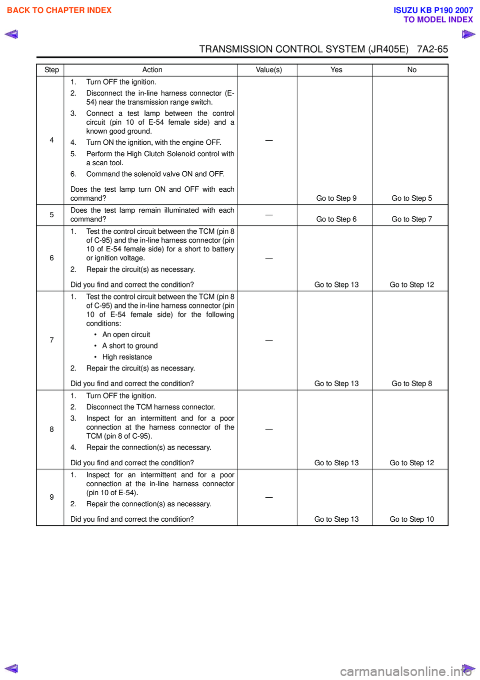
TRANSMISSION CONTROL SYSTEM (JR405E) 7A2-65
41. Turn OFF the ignition.
2. Disconnect the in-line harness connector (E- 54) near the transmission range switch.
3. Connect a test lamp between the control circuit (pin 10 of E-54 female side) and a
known good ground.
4. Turn ON the ignition, with the engine OFF.
5. Perform the High Clutch Solenoid control with a scan tool.
6. Command the solenoid valve ON and OFF.
Does the test lamp turn ON and OFF with each
command? —
Go to Step 9 Go to Step 5
5 Does the test lamp remain illuminated with each
command? —
Go to Step 6 Go to Step 7
6 1. Test the control circuit between the TCM (pin 8
of C-95) and the in-line harness connector (pin
10 of E-54 female side) for a short to battery
or ignition voltage.
2. Repair the circuit(s) as necessary.
Did you find and correct the condition? —
Go to Step 13 Go to Step 12
7 1. Test the control circuit between the TCM (pin 8
of C-95) and the in-line harness connector (pin
10 of E-54 female side) for the following
conditions:
• An open circuit
• A short to ground
• High resistance
2. Repair the circuit(s) as necessary.
Did you find and correct the condition? —
Go to Step 13 Go to Step 8
8 1. Turn OFF the ignition.
2. Disconnect the TCM harness connector.
3. Inspect for an intermittent and for a poor connection at the harness connector of the
TCM (pin 8 of C-95).
4. Repair the connection(s) as necessary.
Did you find and correct the condition? —
Go to Step 13 Go to Step 12
9 1. Inspect for an intermittent and for a poor
connection at the in-line harness connector
(pin 10 of E-54).
2. Repair the connection(s) as necessary.
Did you find and correct the condition? —
Go to Step 13 Go to Step 10
Step
Action Value(s)Yes No
BACK TO CHAPTER INDEX
TO MODEL INDEX
ISUZU KB P190 2007
Page 4350 of 6020
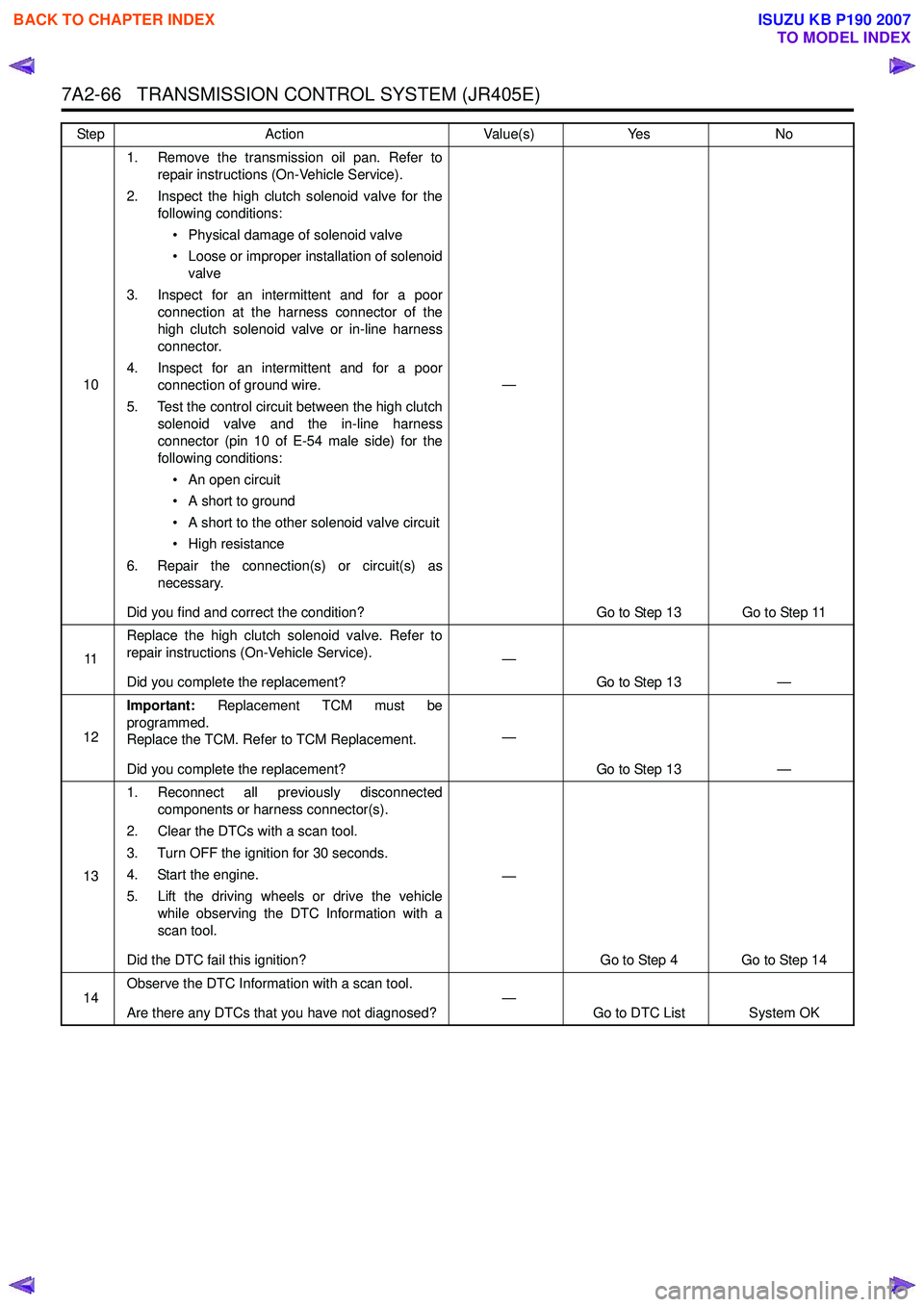
7A2-66 TRANSMISSION CONTROL SYSTEM (JR405E)
101. Remove the transmission oil pan. Refer to
repair instructions (On-Vehicle Service).
2. Inspect the high clutch solenoid valve for the following conditions:
• Physical damage of solenoid valve
• Loose or improper installation of solenoid valve
3. Inspect for an intermittent and for a poor connection at the harness connector of the
high clutch solenoid valve or in-line harness
connector.
4. Inspect for an intermittent and for a poor connection of ground wire.
5. Test the control circuit between the high clutch solenoid valve and the in-line harness
connector (pin 10 of E-54 male side) for the
following conditions:
• An open circuit
• A short to ground
• A short to the other solenoid valve circuit
• High resistance
6. Repair the connection(s) or circuit(s) as necessary.
Did you find and correct the condition? —
Go to Step 13 Go to Step 11
11 Replace the high clutch solenoid valve. Refer to
repair instructions (On-Vehicle Service).
Did you complete the replacement? —
Go to Step 13 —
12 Important:
Replacement TCM must be
programmed.
Replace the TCM. Refer to TCM Replacement.
Did you complete the replacement? —
Go to Step 13 —
13 1. Reconnect all previously disconnected
components or harness connector(s).
2. Clear the DTCs with a scan tool.
3. Turn OFF the ignition for 30 seconds.
4. Start the engine.
5. Lift the driving wheels or drive the vehicle while observing the DTC Information with a
scan tool.
Did the DTC fail this ignition? —
Go to Step 4 Go to Step 14
14 Observe the DTC Information with a scan tool.
Are there any DTCs that you have not diagnosed? —
Go to DTC List System OK
Step
Action Value(s)Yes No
BACK TO CHAPTER INDEX
TO MODEL INDEX
ISUZU KB P190 2007
Page 4352 of 6020

7A2-68 TRANSMISSION CONTROL SYSTEM (JR405E)
41. Turn OFF the ignition.
2. Disconnect the in-line harness connector (E- 54) near the transmission range switch.
3. Connect a test lamp between the control circuit (pin 3 of E-54 female side) and a known
good ground.
4. Turn ON the ignition, with the engine OFF.
5. Perform the Low Clutch Solenoid control with a scan tool.
6. Command the solenoid valve ON and OFF.
Does the test lamp turn ON and OFF with each
command? —
Go to Step 9 Go to Step 5
5 Does the test lamp remain illuminated with each
command? —
Go to Step 6 Go to Step 7
6 1. Test the control circuit between the TCM (pin 9
of C-95) and the in-line harness connector (pin
3 of E-54 female side) for a short to battery or
ignition voltage.
2. Repair the circuit(s) as necessary.
Did you find and correct the condition? —
Go to Step 13 Go to Step 12
7 1. Test the control circuit between the TCM (pin 9
of C-95) and the in-line harness connector (pin
3 of E-54 female side) for the following
conditions:
• An open circuit
• A short to ground
• High resistance
2. Repair the circuit(s) as necessary.
Did you find and correct the condition? —
Go to Step 13 Go to Step 8
8 1. Turn OFF the ignition.
2. Disconnect the TCM harness connector.
3. Inspect for an intermittent and for a poor connection at the harness connector of the
TCM (pin 9 of C-95).
4. Repair the connection(s) as necessary.
Did you find and correct the condition? —
Go to Step 13 Go to Step 12
9 1. Inspect for an intermittent and for a poor
connection at the in-line harness connector
(pin 3 of E-54).
2. Repair the connection(s) as necessary.
Did you find and correct the condition? —
Go to Step 13 Go to Step 10
Step
Action Value(s)Yes No
BACK TO CHAPTER INDEX
TO MODEL INDEX
ISUZU KB P190 2007
Page 4353 of 6020
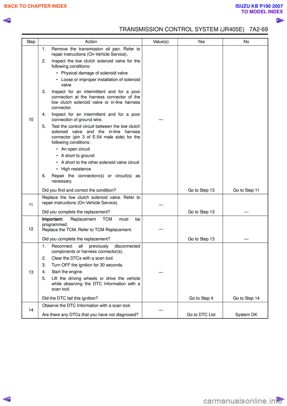
TRANSMISSION CONTROL SYSTEM (JR405E) 7A2-69
101. Remove the transmission oil pan. Refer to
repair instructions (On-Vehicle Service).
2. Inspect the low clutch solenoid valve for the following conditions:
• Physical damage of solenoid valve
• Loose or improper installation of solenoid valve
3. Inspect for an intermittent and for a poor connection at the harness connector of the
low clutch solenoid valve or in-line harness
connector.
4. Inspect for an intermittent and for a poor connection of ground wire.
5. Test the control circuit between the low clutch solenoid valve and the in-line harness
connector (pin 3 of E-54 male side) for the
following conditions:
• An open circuit
• A short to ground
• A short to the other solenoid valve circuit
• High resistance
6. Repair the connection(s) or circuit(s) as necessary.
Did you find and correct the condition? —
Go to Step 13 Go to Step 11
11 Replace the low clutch solenoid valve. Refer to
repair instructions (On-Vehicle Service).
Did you complete the replacement? —
Go to Step 13 —
12 Important:
Replacement TCM must be
programmed.
Replace the TCM. Refer to TCM Replacement.
Did you complete the replacement? —
Go to Step 13 —
13 1. Reconnect all previously disconnected
components or harness connector(s).
2. Clear the DTCs with a scan tool.
3. Turn OFF the ignition for 30 seconds.
4. Start the engine.
5. Lift the driving wheels or drive the vehicle while observing the DTC Information with a
scan tool.
Did the DTC fail this ignition? —
Go to Step 4 Go to Step 14
14 Observe the DTC Information with a scan tool.
Are there any DTCs that you have not diagnosed? —
Go to DTC List System OK
Step
Action Value(s)Yes No
BACK TO CHAPTER INDEX
TO MODEL INDEX
ISUZU KB P190 2007
Page 4356 of 6020
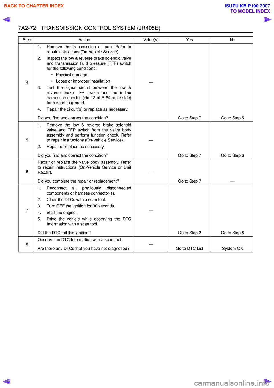
7A2-72 TRANSMISSION CONTROL SYSTEM (JR405E)
41. Remove the transmission oil pan. Refer to
repair instructions (On-Vehicle Service).
2. Inspect the low & reverse brake solenoid valve and transmission fluid pressure (TFP) switch
for the following conditions:
• Physical damage
• Loose or improper installation
3. Test the signal circuit between the low & reverse brake TFP switch and the in-line
harness connector (pin 12 of E-54 male side)
for a short to ground.
4. Repair the circuit(s) or replace as necessary.
Did you find and correct the condition? —
Go to Step 7 Go to Step 5
5 1. Remove the low & reverse brake solenoid
valve and TFP switch from the valve body
assembly and perform function check. Refer
to repair instructions (On-Vehicle Service).
2. Repair or replace as necessary.
Did you find and correct the condition? —
Go to Step 7 Go to Step 6
6 Repair or replace the valve body assembly. Refer
to repair instructions (On-Vehicle Service or Unit
Repair).
Did you complete the repair or replacement? —
Go to Step 7 —
7 1. Reconnect all previously disconnected
components or harness connector(s).
2. Clear the DTCs with a scan tool.
3. Turn OFF the ignition for 30 seconds.
4. Start the engine.
5. Drive the vehicle while observing the DTC Information with a scan tool.
Did the DTC fail this ignition? —
Go to Step 2 Go to Step 8
8 Observe the DTC Information with a scan tool.
Are there any DTCs that you have not diagnosed? —
Go to DTC List System OK
Step
Action Value(s)Yes No
BACK TO CHAPTER INDEX
TO MODEL INDEX
ISUZU KB P190 2007
Page 4358 of 6020
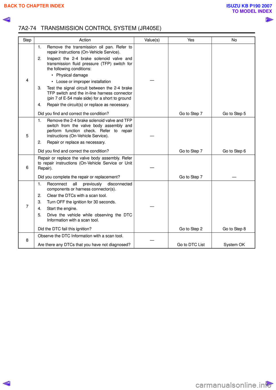
7A2-74 TRANSMISSION CONTROL SYSTEM (JR405E)
41. Remove the transmission oil pan. Refer to
repair instructions (On-Vehicle Service).
2. Inspect the 2-4 brake solenoid valve and transmission fluid pressure (TFP) switch for
the following conditions:
• Physical damage
• Loose or improper installation
3. Test the signal circuit between the 2-4 brake TFP switch and the in-line harness connector
(pin 7 of E-54 male side) for a short to ground
4. Repair the circuit(s) or replace as necessary.
Did you find and correct the condition? —
Go to Step 7 Go to Step 5
5 1. Remove the 2-4 brake solenoid valve and TFP
switch from the valve body assembly and
perform function check. Refer to repair
instructions (On-Vehicle Service).
2. Repair or replace as necessary.
Did you find and correct the condition? —
Go to Step 7 Go to Step 6
6 Repair or replace the valve body assembly. Refer
to repair instructions (On-Vehicle Service or Unit
Repair).
Did you complete the repair or replacement? —
Go to Step 7 —
7 1. Reconnect all previously disconnected
components or harness connector(s).
2. Clear the DTCs with a scan tool.
3. Turn OFF the ignition for 30 seconds.
4. Start the engine.
5. Drive the vehicle while observing the DTC Information with a scan tool.
Did the DTC fail this ignition? —
Go to Step 2 Go to Step 8
8 Observe the DTC Information with a scan tool.
Are there any DTCs that you have not diagnosed? —
Go to DTC List System OK
Step
Action Value(s)Yes No
BACK TO CHAPTER INDEX
TO MODEL INDEX
ISUZU KB P190 2007
Page 4360 of 6020
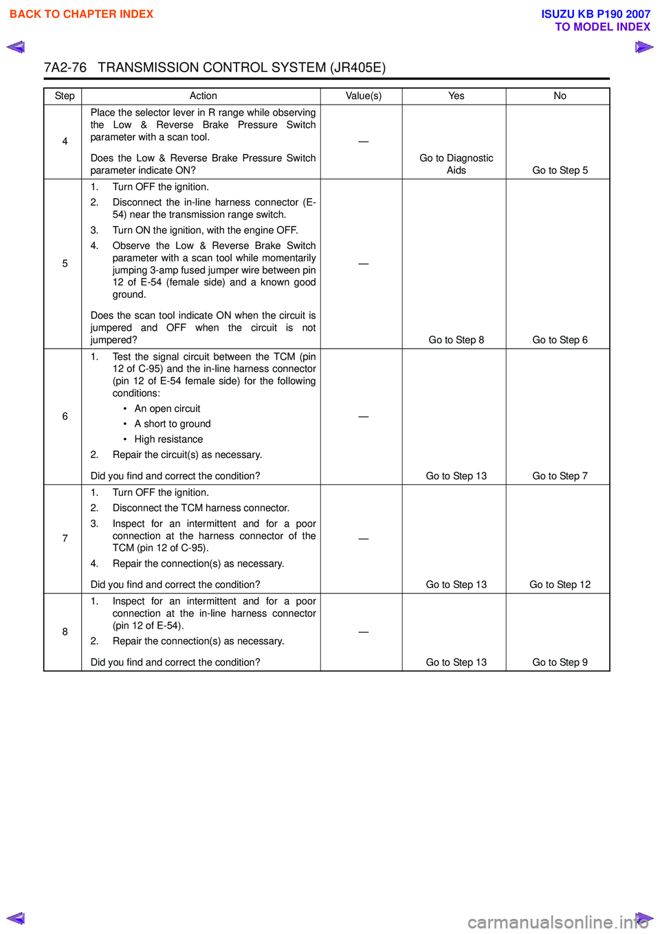
7A2-76 TRANSMISSION CONTROL SYSTEM (JR405E)
4Place the selector lever in R range while observing
the Low & Reverse Brake Pressure Switch
parameter with a scan tool.
Does the Low & Reverse Brake Pressure Switch
parameter indicate ON? —
Go to Diagnostic Aids Go to Step 5
5 1. Turn OFF the ignition.
2. Disconnect the in-line harness connector (E- 54) near the transmission range switch.
3. Turn ON the ignition, with the engine OFF.
4. Observe the Low & Reverse Brake Switch parameter with a scan tool while momentarily
jumping 3-amp fused jumper wire between pin
12 of E-54 (female side) and a known good
ground.
Does the scan tool indicate ON when the circuit is
jumpered and OFF when the circuit is not
jumpered? —
Go to Step 8 Go to Step 6
6 1. Test the signal circuit between the TCM (pin
12 of C-95) and the in-line harness connector
(pin 12 of E-54 female side) for the following
conditions:
• An open circuit
• A short to ground
• High resistance
2. Repair the circuit(s) as necessary.
Did you find and correct the condition? —
Go to Step 13 Go to Step 7
7 1. Turn OFF the ignition.
2. Disconnect the TCM harness connector.
3. Inspect for an intermittent and for a poor connection at the harness connector of the
TCM (pin 12 of C-95).
4. Repair the connection(s) as necessary.
Did you find and correct the condition? —
Go to Step 13 Go to Step 12
8 1. Inspect for an intermittent and for a poor
connection at the in-line harness connector
(pin 12 of E-54).
2. Repair the connection(s) as necessary.
Did you find and correct the condition? —
Go to Step 13 Go to Step 9
Step
Action Value(s)Yes No
BACK TO CHAPTER INDEX
TO MODEL INDEX
ISUZU KB P190 2007