Page 4942 of 6020

8A-4 ELECTRICAL-BODY AND CHASSIS
GENERAL INFORMATION
The body and chassis electrical system operates on a twelve volt power supply with negative ground polarity.
The main harness consists of the engine harness, the instrument harness, the body harness, and the chassis
harness.
The harnesses use a split corrugated tube to protect the wires from the elements.
W ire size is determined by current flow, circuit length, and voltage drop.
All wires have color-coded insulation.
W ire color-codes are shown in the circuit diagrams.
This makes it easier to trace circuits and to make the proper connections.
Each circuit consists of the following:
5. Power source – The battery and the alternator
5. W ires – To carry electrical current through the circuit
5. Fuses – To protect the circuit against current overload
5. Relays – To protect voltage drop between the battery and the circuit parts and to protect the switch points against burning
5. Switches – To open and close the circuit
5. Load – Any device, such as a light or motor, which converts the electrical current into useful work
5. Ground – To allow the current to flow back to the power source
BACK TO CHAPTER INDEX TO MODEL INDEXISUZU KB P190 2007
Page 4945 of 6020

ELECTRICAL-BODY AND CHASSIS 8A-7
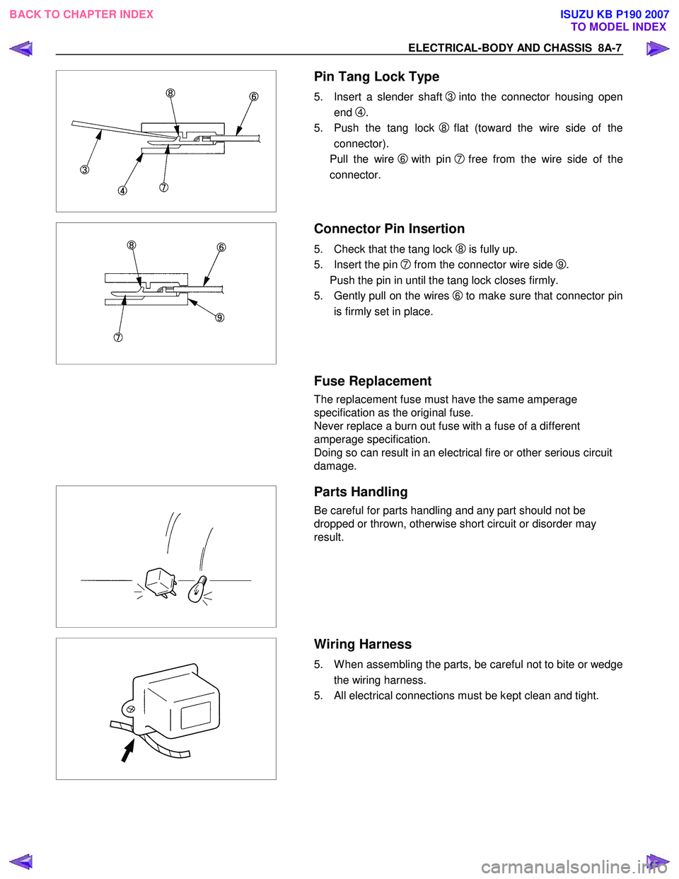
Pin Tang Lock Type
5. Insert a slender shaft 3into the connector housing open
end
4.
5. Push the tang lock
8flat (toward the wire side of the
connector).
Pull the wire
6 with pin 7free from the wire side of the
connector.
Connector Pin Insertion
5. Check that the tang lock 8 is fully up.
5. Insert the pin
7 from the connector wire side 9.
Push the pin in until the tang lock closes firmly.
5. Gently pull on the wires
6to make sure that connector pin
is firmly set in place.
Fuse Replacement
The replacement fuse must have the same amperage
specification as the original fuse.
Never replace a burn out fuse with a fuse of a different
amperage specification.
Doing so can result in an electrical fire or other serious circuit
damage.
Parts Handling
Be careful for parts handling and any part should not be
dropped or thrown, otherwise short circuit or disorder may
result.
Wiring Harness
5. W hen assembling the parts, be careful not to bite or wedge
the wiring harness.
5. All electrical connections must be kept clean and tight.
BACK TO CHAPTER INDEX TO MODEL INDEXISUZU KB P190 2007
Page 4946 of 6020
8A-8 ELECTRICAL-BODY AND CHASSIS
5. Use a grommet or guard tube to protect the wiring harness
from contacting a sharp edge or surface.
5. Position the wiring harness with enough clearance from the
other parts and guard the wiring harness with a vinyl tube
to avoid direct contact.
5. The wiring harness between engine and chassis should be
long enough to prevent chafing or damage due to various
vibrations.
BACK TO CHAPTER INDEX TO MODEL INDEXISUZU KB P190 2007
Page 4947 of 6020

ELECTRICAL-BODY AND CHASSIS 8A-9
SPLICING WIRE
Open the Harness
If the harness is taped, remove the tape.
To avoid wire insulation damage, use a sewing “seam ripper”
(available from sewing supply stores) to cut open the harness.
If the harness has a black plastic conduit, simply pull out the
desired wire.
Cut the wire
Begin by cutting as little wire off the harness as possible.
You may need the extra length of wire later if you decide to cut
more wire off to change the location of a splice.
You may have to adjust splice locations to make certain that
each splice is at least 1-1/2” (40 mm) away from other splices,
harness branches, or connectors.
Strip the insulation
W hen replacing a wire, use a wire of the same size as the
original wire.
Check the stripped wire for nicks or cut strands.
If the wire is damaged, repeat the procedure on a new section
of wire.
The two stripped wire ends should be equal in length.
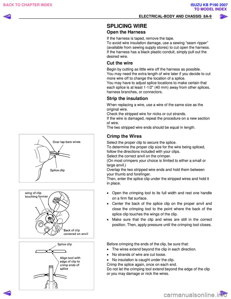
Crimp the Wires
Select the proper clip to secure the splice.
To determine the proper clip size for the wire being spliced,
follow the directions included with your clips.
Select the correct anvil on the crimper.
(On most crimpers your choice is limited to either a small or
large anvil.)
Overlap the two stripped wire ends and hold them between
your thumb and forefinger.
Then, enter the splice clip under the stripped wires and hold it
in place.
•
Open the crimping tool to its full width and rest one handle
on a firm flat surface.
• Center the back of the splice clip on the proper anvil and
close the crimping tool to the point where the back of the
splice clip touches the wings of the clip.
• Make sure that the clip and wires are still in the correct
position. Then, apply pressure until the crimping tool closes.
Before crimping the ends of the clip, be sure that:
• The wires extend beyond the clip in each direction.
• No strands of wire are cut loose.
• No insulation is caught under the clip.
Crimp the splice again, once on each end.
Do not let the crimping tool extend beyond the edge of the clip
or you may damage or nick the wires.
BACK TO CHAPTER INDEX TO MODEL INDEXISUZU KB P190 2007
Page 4948 of 6020
8A-10 ELECTRICAL-BODY AND CHASSIS
Solder
Apply 60/40 rosin core solder to the opening in the back of the
clip.
Follow the manufacturer’s instructions for the solder equipment
you are using.
Tape the Splice
Center and roll the splicing tape.
The tape should cover the entire splice.
Roll on enough tape to duplicate the thickness of the insulation
on the existing wires.
Do not flag the tape.
Flagged tape may not provide enough insulation, and the
flagged ends will tangle with the other wires in the harness.
If the wire does not belong in a conduit or other harness
covering, tape the wire again.
Use a winding motion to cover the first piece of tape.
BACK TO CHAPTER INDEX TO MODEL INDEXISUZU KB P190 2007
Page 4951 of 6020
ELECTRICAL-BODY AND CHASSIS 8A-13
PARTS FOR ELECTRICAL CIRCUIT
WIRING
Wire Color
All wires have color-coded insulation.
W ires belonging to system's main harness will have a single
color.
W ires belonging to a system's sub-circuits will have a colored
stripe.
Striped wires use the following code to show wire size and
colors.
Example: 0.5 G
/ R
Red (Stripe color)
Green (Base color)
W ire size (0.5mm
2)
Abbreviations are used to indicate wire color within a circuit
diagram.
Refer to the following table.
Wire Color-Coding
Color-Coding Meaning Color-Coding Meaning
B Black BR Brown
W W hite LG Light green
R Red GR Gray
G Green P Pink
Y Yellow SB Sky blue
L Blue V Violet
O Orange
BACK TO CHAPTER INDEX
TO MODEL INDEXISUZU KB P190 2007
Page 4953 of 6020

ELECTRICAL-BODY AND CHASSIS 8A-15
NormalBlown
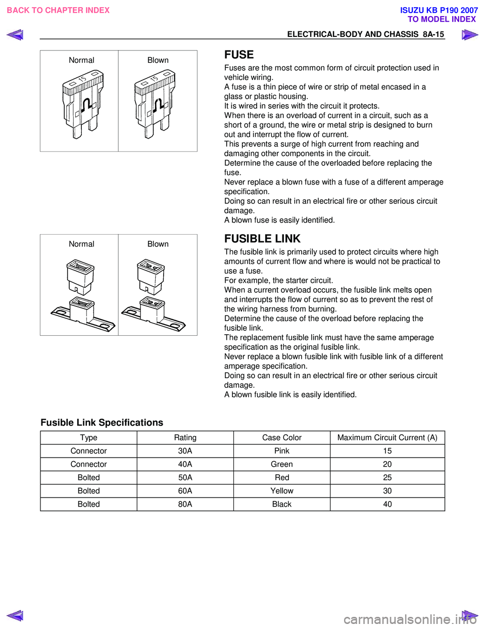
FUSE
Fuses are the most common form of circuit protection used in
vehicle wiring.
A fuse is a thin piece of wire or strip of metal encased in a
glass or plastic housing.
It is wired in series with the circuit it protects.
W hen there is an overload of current in a circuit, such as a
short of a ground, the wire or metal strip is designed to burn
out and interrupt the flow of current.
This prevents a surge of high current from reaching and
damaging other components in the circuit.
Determine the cause of the overloaded before replacing the
fuse.
Never replace a blown fuse with a fuse of a different amperage
specification.
Doing so can result in an electrical fire or other serious circuit
damage.
A blown fuse is easily identified.
Normal Blown
FUSIBLE LINK
The fusible link is primarily used to protect circuits where high
amounts of current flow and where is would not be practical to
use a fuse.
For example, the starter circuit.
W hen a current overload occurs, the fusible link melts open
and interrupts the flow of current so as to prevent the rest of
the wiring harness from burning.
Determine the cause of the overload before replacing the
fusible link.
The replacement fusible link must have the same amperage
specification as the original fusible link.
Never replace a blown fusible link with fusible link of a different
amperage specification.
Doing so can result in an electrical fire or other serious circuit
damage.
A blown fusible link is easily identified.
Fusible Link Specifications
Type Rating Case Color Maximum Circuit Current (A)
Connector 30A Pink 15
Connector 40A Green 20
Bolted 50A Red 25
Bolted 60A Yellow 30
Bolted 80A Black 40
BACK TO CHAPTER INDEX
TO MODEL INDEXISUZU KB P190 2007
Page 4960 of 6020
8A-22 ELECTRICAL-BODY AND CHASSIS
READING THE CIRCUIT DIAGRAM
In this manual, each system has its own parts location illustration and circuit diagram.
And connector configurations used in the circuit diagram are shown at the end of this manual.
PARTS LOCATION: The parts location shows the location of the connectors
1 and the harnesses 2 used in the
each system.
CIRCUIT DIAGRAM: The circuit diagram shows the power supply
3, the load or loads 4 and the grounding
point(s)
5.
CONNECTOR LIST: The connector configuration shows each connector's number
6, configuration 7 and the pin
numbers
8, parts name 9 , connector color 10.
PARTS LOCATION
RTW 780MF002401
BACK TO CHAPTER INDEX
TO MODEL INDEXISUZU KB P190 2007