Page 5284 of 6020

8A-346 ELECTRICAL-BODY AND CHASSIS
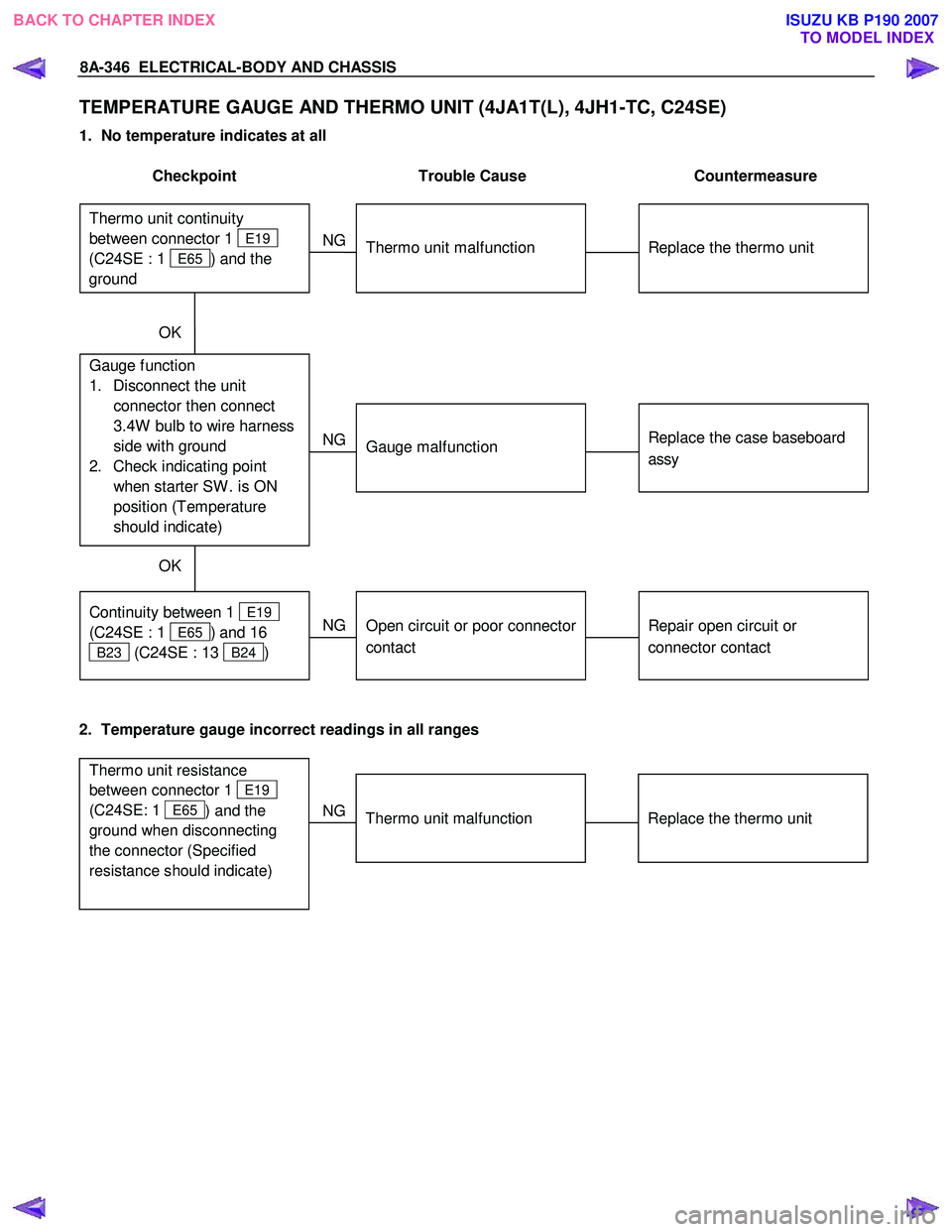
TEMPERATURE GAUGE AND THERMO UNIT (4JA1T(L), 4JH1-TC, C24SE)
1. No temperature indicates at all
Checkpoint Trouble Cause Countermeasure
Replace the thermo unit
Thermo unit malfunction
NG
Replace the case baseboard
assy
Gauge function
1. Disconnect the unit connector then connect
3.4W bulb to wire harness
side with ground
2. Check indicating point when starter SW . is ON
position (Temperature
should indicate)
Gauge malfunction
Repair open circuit or
connector contact
Continuity between 1 E19
(C24SE : 1
E65 ) and 16
B23 (C24SE : 13 B24 )
Open circuit or poor connector
contact
NG
NG
OK
OK
Thermo unit continuity
between connector 1
E19
(C24SE : 1
E65 ) and the
ground
2. Temperature gauge incorrect readings in all ranges
Replace the thermo unit
Thermo unit malfunction
NG
Thermo unit resistance
between connector 1
E19
(C24SE: 1
E65 ) and the
ground when disconnecting
the connector (Specified
resistance should indicate)
BACK TO CHAPTER INDEX
TO MODEL INDEXISUZU KB P190 2007
Page 5285 of 6020

ELECTRICAL-BODY AND CHASSIS 8A-347
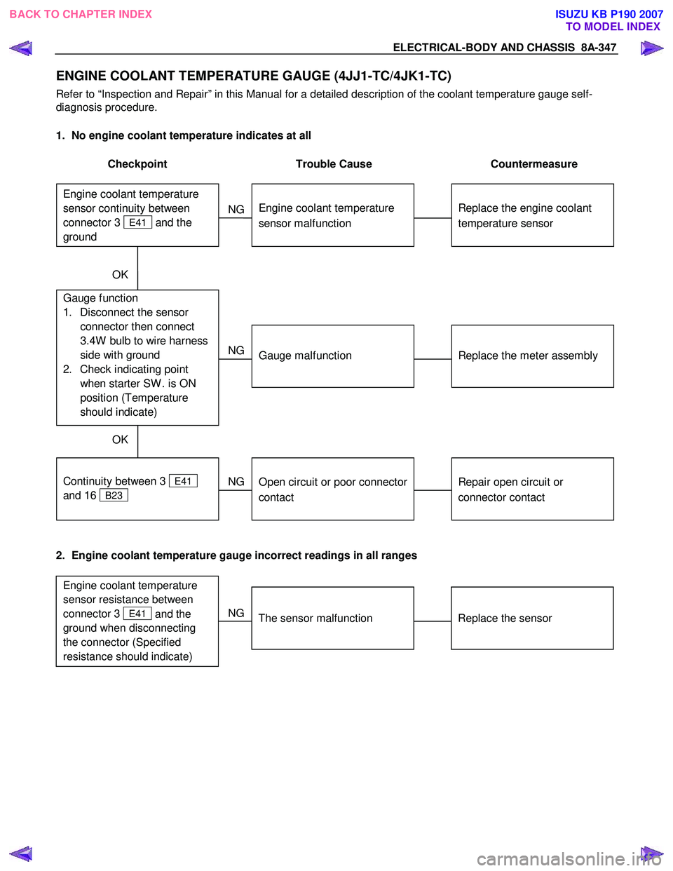
ENGINE COOLANT TEMPERATURE GAUGE (4JJ1-TC/4JK1-TC)
Refer to “Inspection and Repair” in this Manual for a detailed description of the coolant temperature gauge self-
diagnosis procedure.
1. No engine coolant temperature indicates at all
Checkpoint Trouble Cause Countermeasure
Replace the engine coolant
temperature sensor
Engine coolant temperature
sensor malfunction
NG
Replace the meter assembly
Gauge function
1. Disconnect the sensor connector then connect
3.4W bulb to wire harness
side with ground
2. Check indicating point when starter SW . is ON
position (Temperature
should indicate)
Gauge malfunction
Repair open circuit or
connector contact
Continuity between 3
E41
and 16
B23
Open circuit or poor connector
contact
NG
NG
OK
OK
Engine coolant temperature
sensor continuity between
connector 3
E41 and the
ground
2. Engine coolant temperature gauge incorrect readings in all ranges
Replace the sensor
The sensor malfunction
NG
Engine coolant temperature
sensor resistance between
connector 3
E41 and the
ground when disconnecting
the connector (Specified
resistance should indicate)
BACK TO CHAPTER INDEX
TO MODEL INDEXISUZU KB P190 2007
Page 5286 of 6020
8A-348 ELECTRICAL-BODY AND CHASSIS
TEMPERATURE GAUGE AND THERMO UNIT (HFV6)
1. No temperature indicates at all
Checkpoint Trouble Cause Countermeasure
Replace the thermo unit
Thermo unit malfunction
NG
Replace the case baseboard
assy
Gauge function
1. Disconnect the unit connector then connect
3.4W bulb to wire harness
side with ground
2. Check indicating point when starter SW . is ON
position (Temperature
should indicate)
Gauge malfunction
Repair open circuit or
connector contact
Continuity between 8 B96
and 16
B23
Open circuit or poor connector
contact
NG
NG
OK
OK
PIM (Thermo unit) continuity
between connector 8
B96
and the ground
2. Temperature gauge incorrect readings in all ranges
Replace the thermo unit
Thermo unit malfunction
NG
PIM (Thermo unit) resistance
between connector 8
B96
and the ground when
disconnecting the connector
(Specified resistance should
indicate)
BACK TO CHAPTER INDEX TO MODEL INDEXISUZU KB P190 2007
Page 5287 of 6020
ELECTRICAL-BODY AND CHASSIS 8A-349
FUEL GAUGE AND FUEL TANK UNIT (C24SE, 4JJA1T(L), 4JH1-TC, 4JJ1-TC/4JK1-TC)
1. No fuel level indicates at all
Checkpoint Trouble Cause Countermeasure
Replace the tank unit
Open circuit inside the tank
unit
NG
Thermo unit malfunction
Replace the case baseboard
assy
Fuel gauge function
1. Disconnect the tank unit connector then connect
3.4W bulb to wire harness
side
2. Check indicating point when starter SW . is ON
position (Fuel level should
indicate)
Gauge malfunction
Repair open circuit or
connector contact
Continuity between
connectors 17
B23 (C24SE :
14
B24 ) and 3
F2
Open circuit or poor connector
contact
NG
NG
OK
OK
Tank unit continuity between
connector 3
F2 and ground
2. Fuel gauge gives incorrect readings in all ranges
Replace the tank unitTank unit malfunction
NG
Tank unit resistance position
with the float at checking
points (Specified resistance
should indicate)
BACK TO CHAPTER INDEX
TO MODEL INDEXISUZU KB P190 2007
Page 5288 of 6020
8A-350 ELECTRICAL-BODY AND CHASSIS
FUEL GAUGE AND FUEL TANK UNIT (HFV6)
1. No fuel level indicates at all
Checkpoint Trouble Cause Countermeasure
Replace the tank unit
Open circuit inside the tank
unit
NG
Thermo unit malfunction
Replace the case baseboard
assy
Fuel gauge function
1. Disconnect the tank unit connector then connect
3.4W bulb to wire harness
side
2. Check indicating point when starter SW . is ON
position (Fuel level should
indicate)
Gauge malfunction
Repair open circuit or
connector contact
Continuity between
connectors 17
B23 and 17
B96
Open circuit or poor connector
contact
NG
NG
OK
OK
PIM (Tank unit) continuity
between connector 17
B96
and ground
2. Fuel gauge gives incorrect readings in all ranges
Replace the tank unitTank unit malfunction
NG
Tank unit resistance position
with the float at checking
points (Specified resistance
should indicate)
BACK TO CHAPTER INDEX TO MODEL INDEXISUZU KB P190 2007
Page 5291 of 6020
ELECTRICAL-BODY AND CHASSIS 8A-353
REMOVAL AND INSTALLATION
RTW 780SH001701
This illustration is based on RHD model
METER ASSEMBLY
Removal
1. Meter Cluster Assembly
• Refer to the removal steps of “INSTRUMENT PANEL” in
Section 10 “CAB”
2. Meter Assembly • Remove three screws of the meter assembly.
• Disconnect the meter connectors.
Installation
Follow the removal procedure in the reverse order to install the
meter.
Pay close attention to the important points mentioned in the
following paragraphs.
Connector
Be absolutely sure that the meter connectors are securely
connected.
This will prevent a poor contact and an open circuit.
Wire Harness
Do not pinch the wire harness between the cluster and the
meter hood during the meter assembly installation procedure.
W ire damage will result.
BACK TO CHAPTER INDEX
TO MODEL INDEXISUZU KB P190 2007
Page 5345 of 6020
ELECTRICAL-BODY AND CHASSIS 8A-407
TROUBLESHOOTING
QUICK CHART FOR CHECK POINTS
Check Points Fuse C21
(20A) Power
Window &
Door Lock Switch Door
Lock
Switch Key Cylinder
switch Door Lock Actuator
Cable
Trouble Mode Driver’s
side Driver’s
side D/S P/S Passen
ger’s side RR-RH RR-LH
Harness
1. All the doors do not
lock and unlock
2. All the doors do not get locked (or
unlocked)
3. Driver’s side door
does not get locked
(or unlocked)
4. FRT passenger’s side
door does not get
locked (or unlocked)
5. RR door-RH does not
get locked (or
unlocked)
6. RR door-LH does not
get locked (or
unlocked)
7. Door lock does not
operate when
operating from the
driver’s seat side
BACK TO CHAPTER INDEX
TO MODEL INDEXISUZU KB P190 2007
Page 5346 of 6020

8A-408 ELECTRICAL-BODY AND CHASSIS
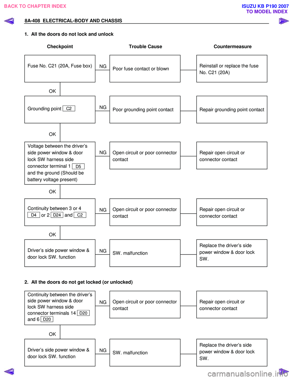
1. All the doors do not lock and unlock
Checkpoint Trouble Cause Countermeasure
Reinstall or replace the fuse
No. C21 (20A)
Poor fuse contact or blown
NG
Repair grounding point contact
Grounding point C2
Poor grounding point contact
Repair open circuit or
connector contact
Voltage between the driver’s
side power window & door
lock SW harness side
connector terminal 1
D5
and the ground (Should be
battery voltage present)
Open circuit or poor connector
contact
NG
NG
OK
OK
OK
Fuse No. C21 (20A, Fuse box)
Repair open circuit or
connector contact
Open circuit or poor connector
contact
NG
Replace the driver’s side
power window & door lock
SW .
Driver’s side power window &
door lock SW . function
SW . malfunction
NG
OK
Continuity between 3 or 4
D4 or 2 D24 and
C2
2. All the doors do not get locked (or unlocked)
Repair open circuit or
connector contact
Open circuit or poor connector
contact
NG
Replace the driver’s side
power window & door lock
SW .
Driver’s side power window &
door lock SW . function
SW . malfunction
NG
OK
Continuity between the driver’s
side power window & door
lock SW harness side
connector terminals 14
D20
and 6
D20
BACK TO CHAPTER INDEX TO MODEL INDEXISUZU KB P190 2007