2007 ISUZU KB P190 Harness
[x] Cancel search: HarnessPage 5480 of 6020
8A-542 ELECTRICAL-BODY AND CHASSIS
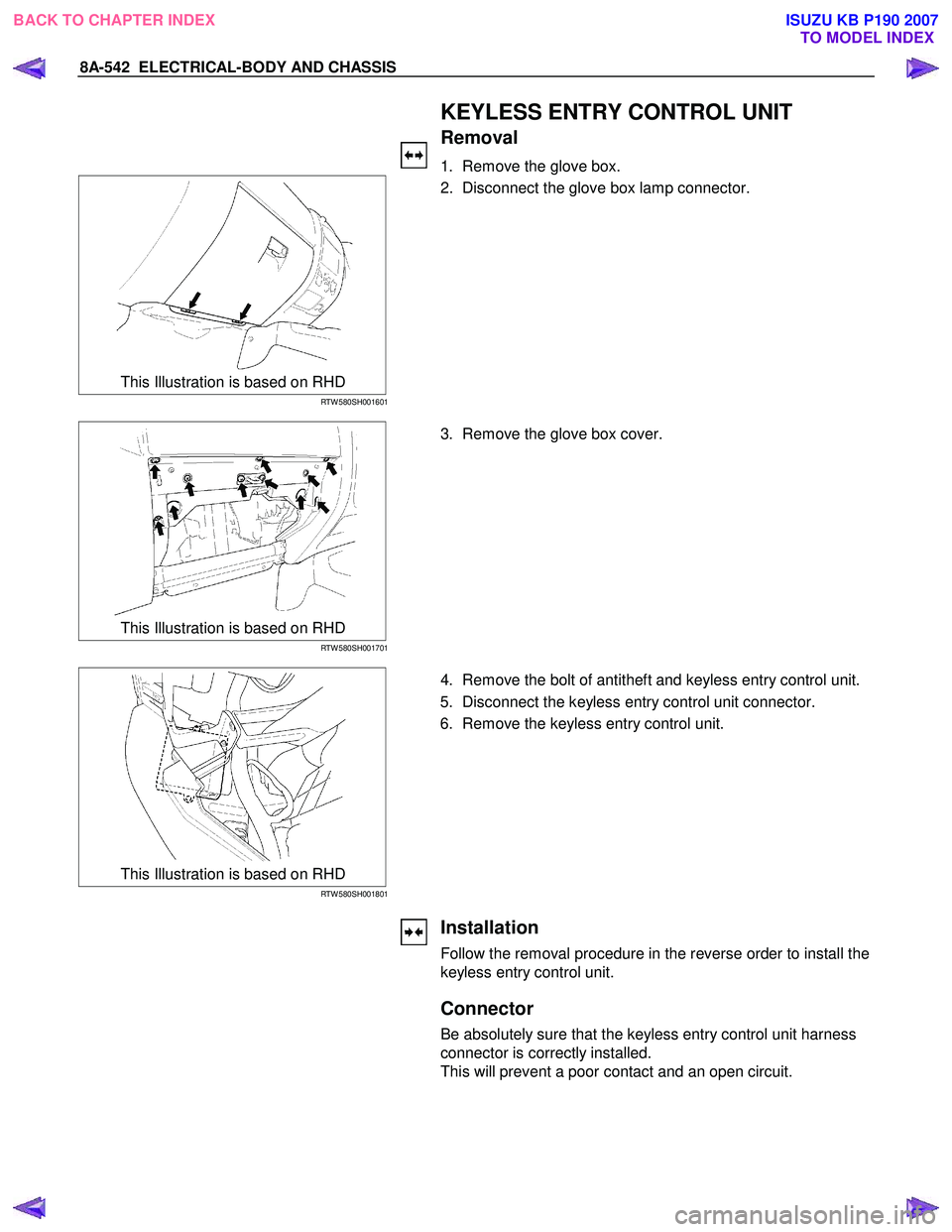
KEYLESS ENTRY CONTROL UNIT
Removal
1. Remove the glove box.
This Illustration is based on RHD
RTW 580SH001601
2. Disconnect the glove box lamp connector.
This Illustration is based on RHD
RTW 580SH001701
3. Remove the glove box cover.
This Illustration is based on RHD
RTW 580SH001801
4. Remove the bolt of antitheft and keyless entry control unit.
5. Disconnect the keyless entry control unit connector.
6. Remove the keyless entry control unit.
Installation
Follow the removal procedure in the reverse order to install the
keyless entry control unit.
Connector
Be absolutely sure that the keyless entry control unit harness
connector is correctly installed.
This will prevent a poor contact and an open circuit.
BACK TO CHAPTER INDEX TO MODEL INDEXISUZU KB P190 2007
Page 5516 of 6020
8A-578 ELECTRICAL-BODY AND CHASSIS
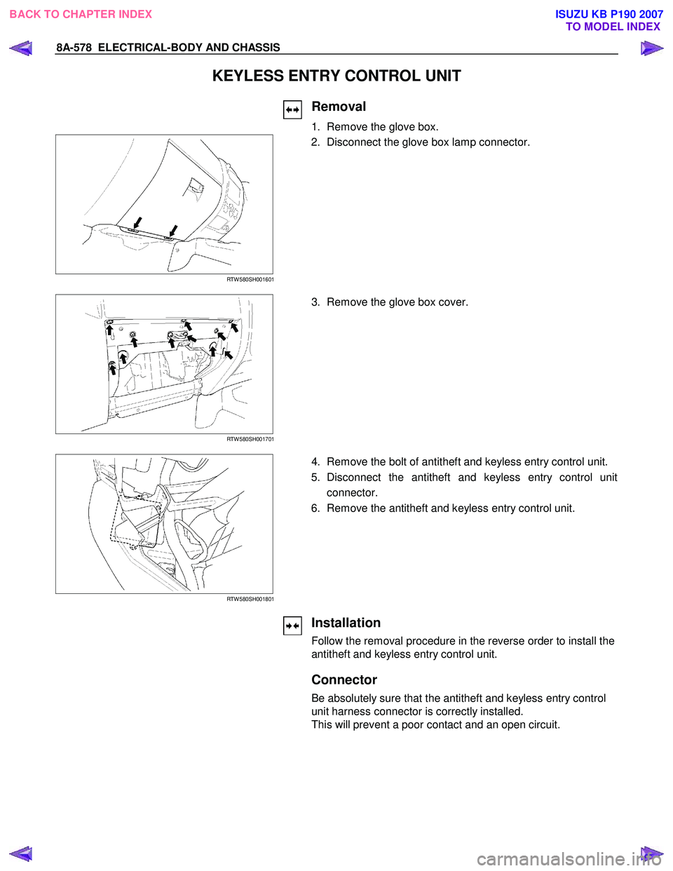
KEYLESS ENTRY CONTROL UNIT
Removal
1. Remove the glove box.
RTW 580SH001601
2. Disconnect the glove box lamp connector.
RTW 580SH001701
3. Remove the glove box cover.
RTW 580SH001801
4. Remove the bolt of antitheft and keyless entry control unit.
5. Disconnect the antitheft and keyless entry control unitconnector.
6. Remove the antitheft and keyless entry control unit.
Installation
Follow the removal procedure in the reverse order to install the
antitheft and keyless entry control unit.
Connector
Be absolutely sure that the antitheft and keyless entry control
unit harness connector is correctly installed.
This will prevent a poor contact and an open circuit.
BACK TO CHAPTER INDEX TO MODEL INDEXISUZU KB P190 2007
Page 5564 of 6020
8A-626 ELECTRICAL-BODY AND CHASSIS
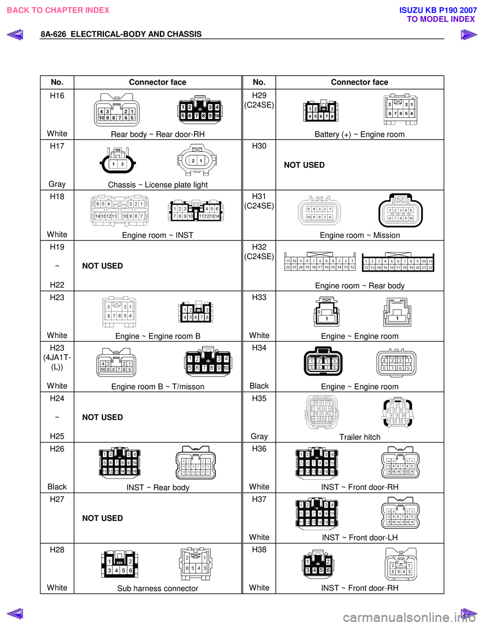
No. Connector face No. Connector face
H16
White
Rear body ~ Rear door-RH H29
(C24SE)
Battery (+) ~ Engine room
H17
Gray
Chassis ~ License plate light H30
NOT USED
H18
White
Engine room ~ INST H31
(C24SE)
Engine room ~ Mission
H19
~
H22 NOT USED H32
(C24SE)
Engine room ~ Rear body
H23
White
Engine ~ Engine room B H33
WhiteEngine ~ Engine room
H23
(4JA1T- (L))
White
Engine room B ~ T/misson H34
BlackEngine ~ Engine room
H24
~
H25 NOT USED H35
Gray
Trailer hitch
H26
Black
INST ~ Rear body H36
WhiteINST ~ Front door-RH
H27
NOT USED H37
White
INST ~ Front door-LH
H28
White
Sub harness connector H38
WhiteINST ~ Front door-RH
BACK TO CHAPTER INDEX TO MODEL INDEXISUZU KB P190 2007
Page 5582 of 6020
Cruise Control – HFV6 Page 8C–4
NOTE Defined
A NOTE statement immediately precedes or follows an operating procedure, maintenance practice or condition that
requires highlighting. A NOTE statement also emphasises necessary characteristics of a diagnostic or repair procedure.
A NOTE statement is designed to:
• Clarify a procedure,
• Present additional information for accomplishing a procedure,
• Give insight into the reasons for performing a procedure in the recommended manner, and / or
• Present information that gives the technician the benefit of past experience in accomplishing a procedure with
greater ease.
1.2 System Components
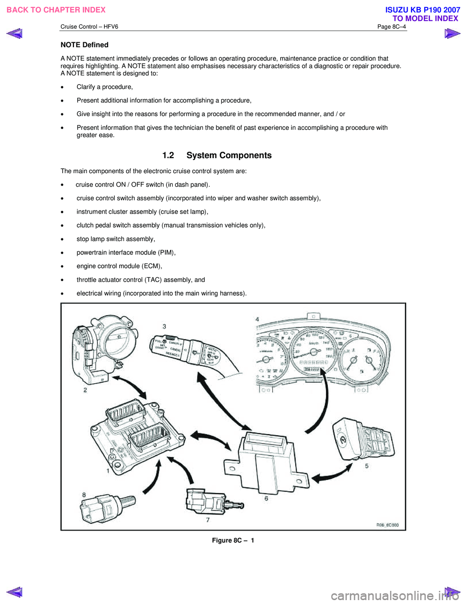
The main components of the electronic cruise control system are:
• cruise control ON / OFF switch (in dash panel).
• cruise control switch assembly (incorporated into wiper and washer switch assembly),
• instrument cluster assembly (cruise set lamp),
• clutch pedal switch assembly (manual transmission vehicles only),
• stop lamp switch assembly,
• powertrain interface module (PIM),
• engine control module (ECM),
• throttle actuator control (TAC) assembly, and
• electrical wiring (incorporated into the main wiring harness).
Figure 8C – 1
BACK TO CHAPTER INDEX TO MODEL INDEXISUZU KB P190 2007
Page 5583 of 6020
Cruise Control – HFV6 Page 8C–5
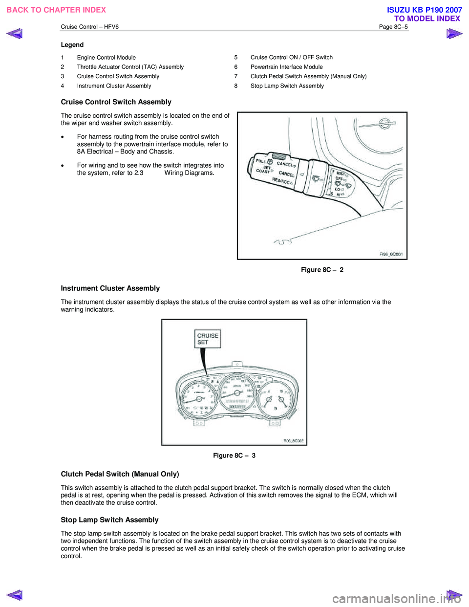
Legend
1 Engine Control Module
2 Throttle Actuator Control (TAC) Assembly
3 Cruise Control Switch Assembly
4 Instrument Cluster Assembly 5 Cruise Control ON / OFF Switch
6 Powertrain Interface Module
7 Clutch Pedal Switch Assembly (Manual Only)
8 Stop Lamp Switch Assembly
Cruise Control Switch Assembly
The cruise control switch assembly is located on the end of
the wiper and washer switch assembly.
• For harness routing from the cruise control switch
assembly to the powertrain interface module, refer to
8A Electrical – Body and Chassis.
• For wiring and to see how the switch integrates into
the system, refer to 2.3 W iring Diagrams.
Figure 8C – 2
Instrument Cluster Assembly
The instrument cluster assembly displays the status of the cruise control system as well as other information via the
warning indicators.
Figure 8C – 3
Clutch Pedal Switch (Manual Only)
This switch assembly is attached to the clutch pedal support bracket. The switch is normally closed when the clutch
pedal is at rest, opening when the pedal is pressed. Activation of this switch removes the signal to the ECM, which will
then deactivate the cruise control.
Stop Lamp Switch Assembly
The stop lamp switch assembly is located on the brake pedal support bracket. This switch has two sets of contacts with
two independent functions. The function of the switch assembly in the cruise control system is to deactivate the cruise
control when the brake pedal is pressed as well as an initial safety check of the switch operation prior to activating cruise
control.
BACK TO CHAPTER INDEX TO MODEL INDEXISUZU KB P190 2007
Page 5592 of 6020
Cruise Control – HFV6 Page 8C–14
2.4 Cruise Control Inoperative /
Malfunctioning
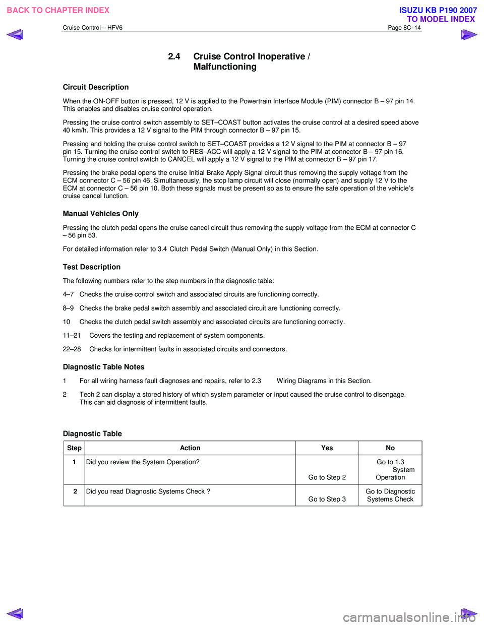
Circuit Description
When the ON-OFF button is pressed, 12 V is applied to the Powertrain Interface Module (PIM) connector B – 97 pin 14.
This enables and disables cruise control operation.
Pressing the cruise control switch assembly to SET–COAST button activates the cruise control at a desired speed above
40 km/h. This provides a 12 V signal to the PIM through connector B – 97 pin 15.
Pressing and holding the cruise control switch to SET–COAST provides a 12 V signal to the PIM at connector B – 97
pin 15. Turning the cruise control switch to RES–ACC will apply a 12 V signal to the PIM at connector B – 97 pin 16.
Turning the cruise control switch to CANCEL will apply a 12 V signal to the PIM at connector B – 97 pin 17.
Pressing the brake pedal opens the cruise Initial Brake Apply Signal circuit thus removing the supply voltage from the
ECM connector C – 56 pin 46. Simultaneously, the stop lamp circuit will close (normally open) and supply 12 V to the
ECM at connector C – 56 pin 10. Both these signals must be present so as to ensure the safe operation of the vehicle’s
cruise cancel function.
Manual Vehicles Only
Pressing the clutch pedal opens the cruise cancel circuit thus removing the supply voltage from the ECM at connector C
– 56 pin 53.
For detailed information refer to 3.4 Clutch Pedal Switch (Manual Only) in this Section.
Test Description
The following numbers refer to the step numbers in the diagnostic table:
4–7 Checks the cruise control switch and associated circuits are functioning correctly.
8–9 Checks the brake pedal switch assembly and associated circuit are functioning correctly.
10 Checks the clutch pedal switch assembly and associated circuits are functioning correctly.
11–21 Covers the testing and replacement of system components.
22–28 Checks for intermittent faults in associated circuits and connectors.
Diagnostic Table Notes
1 For all wiring harness fault diagnoses and repairs, refer to 2.3 W iring Diagrams in this Section.
2 Tech 2 can display a stored history of which system parameter or input caused the cruise control to disengage. This can aid diagnosis of intermittent faults.
Diagnostic Table
Step Action Yes No
1 Did you review the System Operation?
Go to Step 2 Go to 1.3
System Operation
2 Did you read Diagnostic Systems Check ?
Go to Step 3 Go to Diagnostic
Systems Check
BACK TO CHAPTER INDEX TO MODEL INDEXISUZU KB P190 2007
Page 5595 of 6020
Cruise Control – HFV6 Page 8C–17
Step Action Yes No
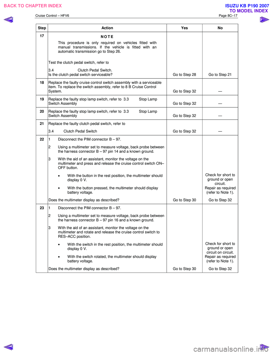
17
NOTE
This procedure is only required on vehicles fitted with
manual transmissions. If the vehicle is fitted with an
automatic transmission go to Step 26.
Test the clutch pedal switch, refer to
3.4 Clutch Pedal Switch.
Is the clutch pedal switch serviceable? Go to Step 28 Go to Step 21
18 Replace the faulty cruise control switch assembly with a serviceable
item. To replace the switch assembly, refer to 8 B Cruise Control
System. Go to Step 32 —
19 Replace the faulty stop lamp switch, refer to 3.3 Stop Lamp
Switch Assembly Go to Step 32 —
20 Replace the faulty stop lamp switch, refer to 3.3 Stop Lamp
Switch Assembly Go to Step 32 —
21
Replace the faulty clutch pedal switch, refer to
3.4 Clutch Pedal Switch Go to Step 32 —
22 1 Disconnect the PIM connector B – 97.
2 Using a multimeter set to measure voltage, back probe between the harness connector B – 97 pin 14 and a known ground.
3 W ith the aid of an assistant, monitor the voltage on the multimeter and press and release the cruise control switch ON–
OFF button.
• W ith the button in the rest position, the multimeter should
display 0 V.
• W ith the button pressed, the multimeter should display
battery voltage.
Does the multimeter display as described? Go to Step 30 Check for short to
ground or open circuit.
Repair as required
(refer to Note 1).
Go to Step 32
23 1 Disconnect the PIM connector B – 97.
2 Using a multimeter set to measure voltage, back probe between the harness connector B – 97 pin 16 and a known ground.
3 With the aid of an assistant, monitor the voltage on the multimeter and rotate and release the cruise control switch to
RES–ACC position.
• With the switch in the rest position, the multimeter should
display 0 V.
• With the switch rotated, the multimeter should display
battery voltage.
Does the multimeter display as described? Go to Step 30 Check for short to
ground or open
circuit on circuit.
Repair as required
(refer to Note 1).
Go to Step 32
BACK TO CHAPTER INDEX TO MODEL INDEXISUZU KB P190 2007
Page 5596 of 6020
Cruise Control – HFV6 Page 8C–18
Step Action Yes No
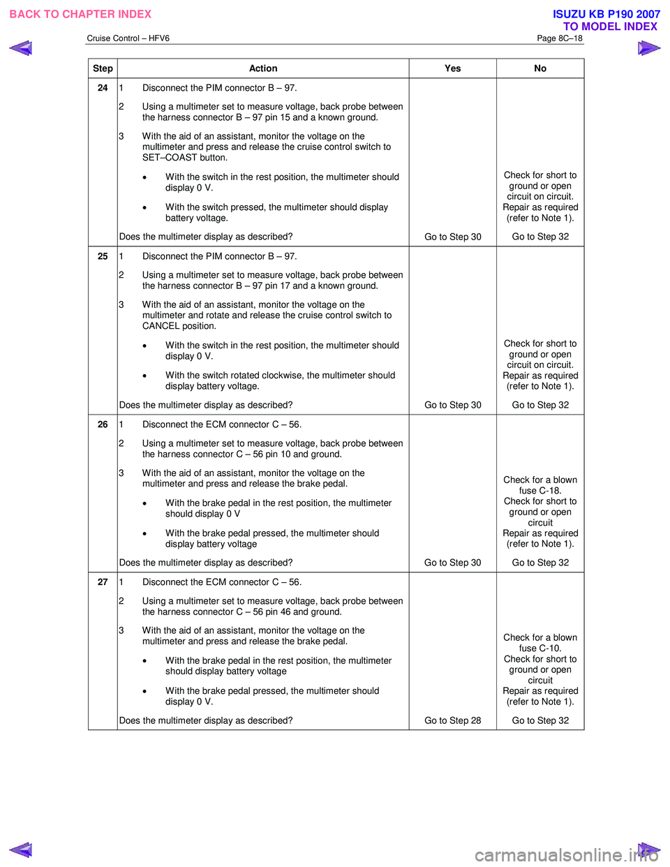
24 1 Disconnect the PIM connector B – 97.
2 Using a multimeter set to measure voltage, back probe between the harness connector B – 97 pin 15 and a known ground.
3 With the aid of an assistant, monitor the voltage on the multimeter and press and release the cruise control switch to
SET–COAST button.
• With the switch in the rest position, the multimeter should
display 0 V.
• With the switch pressed, the multimeter should display
battery voltage.
Does the multimeter display as described? Go to Step 30 Check for short to
ground or open
circuit on circuit.
Repair as required (refer to Note 1).
Go to Step 32
25 1 Disconnect the PIM connector B – 97.
2 Using a multimeter set to measure voltage, back probe between the harness connector B – 97 pin 17 and a known ground.
3 W ith the aid of an assistant, monitor the voltage on the multimeter and rotate and release the cruise control switch to
CANCEL position.
• With the switch in the rest position, the multimeter should
display 0 V.
• W ith the switch rotated clockwise, the multimeter should
display battery voltage.
Does the multimeter display as described? Go to Step 30 Check for short to
ground or open
circuit on circuit.
Repair as required (refer to Note 1).
Go to Step 32
26 1 Disconnect the ECM connector C – 56.
2 Using a multimeter set to measure voltage, back probe between the harness connector C – 56 pin 10 and ground.
3 With the aid of an assistant, monitor the voltage on the multimeter and press and release the brake pedal.
• W ith the brake pedal in the rest position, the multimeter
should display 0 V
• W ith the brake pedal pressed, the multimeter should
display battery voltage
Does the multimeter display as described? Go to Step 30 Check for a blown
fuse C-18.
Check for short to
ground or open circuit
Repair as required (refer to Note 1).
Go to Step 32
27 1 Disconnect the ECM connector C – 56.
2 Using a multimeter set to measure voltage, back probe between the harness connector C – 56 pin 46 and ground.
3 With the aid of an assistant, monitor the voltage on the multimeter and press and release the brake pedal.
• W ith the brake pedal in the rest position, the multimeter
should display battery voltage
• W ith the brake pedal pressed, the multimeter should
display 0 V.
Does the multimeter display as described? Go to Step 28 Check for a blown
fuse C-10.
Check for short to ground or open
circuit
Repair as required (refer to Note 1).
Go to Step 32
BACK TO CHAPTER INDEX TO MODEL INDEXISUZU KB P190 2007