Page 5131 of 6020

ELECTRICAL-BODY AND CHASSIS 8A-193
RTW 48ASH000701
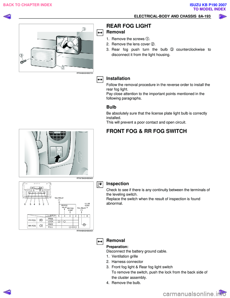
REAR FOG LIGHT
Removal
1. Remove the screws 1.
2. Remove the lens cover
2.
3. Rear fog push turn the bulb
3 counterclockwise to
disconnect it from the light housing.
Installation
Follow the removal procedure in the reverse order to install the
rear fog light.
Pay close attention to the important points mentioned in the
following paragraphs.
Bulb
Be absolutely sure that the license plate light bulb is correctly
installed.
This will prevent a poor contact and open circuit.
RTW 78ASH000401
FRONT FOG & RR FOG SWITCH
RTW 48ASH000401
Inspection
Check to see if there is any continuity between the terminals of
the leveling switch.
Replace the switch when the result of inspection is found
abnormal.
Removal
Preparation:
Disconnect the battery ground cable.
1. Ventilation grille
2. Harness connector
3. Front fog light & Rear fog light switch To remove the switch, push the lock from the back side of
the cluster assembly.
4. Remove the bulb.
BACK TO CHAPTER INDEX TO MODEL INDEXISUZU KB P190 2007
Page 5137 of 6020
ELECTRICAL-BODY AND CHASSIS 8A-199
HEADLIGHT LEVELING SWITCH
Incorrect beam angle due to load change can be corrected.
A four position switch, 0-3, can alter the beam angle through
1.7 degrees on the long wheel base model and 2.17 degrees
on the short wheel base model.
RTW 68ASH000501
Inspection
Check to see if there is any continuity between the terminals of
the leveling switch.
Replace the switch when the result of inspection is found
abnormal.
RTW 78ASH000601
Removal
Preparation:
Disconnect the battery ground cable.
1. Ventilation grille
2. Harness connector
3. Headlight leveling switch To remove the switch, push the lock from the back side of
the cluster assembly.
Installation
To install, follow the removal steps in the reverse noting the
following point.
1. Push in the switch with your fingers until it locks securely.
BACK TO CHAPTER INDEX TO MODEL INDEXISUZU KB P190 2007
Page 5150 of 6020
8A-212 ELECTRICAL-BODY AND CHASSIS
RTU4Z0SH000901
ILLUMINATION SWITCH
RTW 48ASH000601
Inspection
Check to see if there is any continuity between the terminals of
the switch.
Replace the switch when the result of inspection is found
abnormal.
RTW 78ASH000701
Removal
Preparation:
Disconnect the battery ground cable.
1. Instrument panel driver lower cover assembly
Refer to the removal steps Sec.10
2. Harness switch
3. Illumination control
1
To remove the switch, push the lock from the back side of
the cluster assembly.
4. Remove the bulb.
BACK TO CHAPTER INDEX TO MODEL INDEXISUZU KB P190 2007
Page 5181 of 6020
ELECTRICAL-BODY AND CHASSIS 8A-243
RTW 78ASH002001
A Type
RTW 78ASH002101
3. Push the horn switch area1 and area-2. At that time check
the audible noise from each snap stud. (Should be no noise
present)
4. Enable the SRS (Refer to “Enabling the SRS” in Section 9A).
B Type
RTW 780SH003101
INSPECTION AND REPAIR
Switch side Harness side
B60 B60
TURN SIGNAL SWITCH
Lighting Switch Connections
Terminal No.
SW position 5 6 7
Left
Neutral
Right
Turning
direction
BACK TO CHAPTER INDEX TO MODEL INDEXISUZU KB P190 2007
Page 5212 of 6020

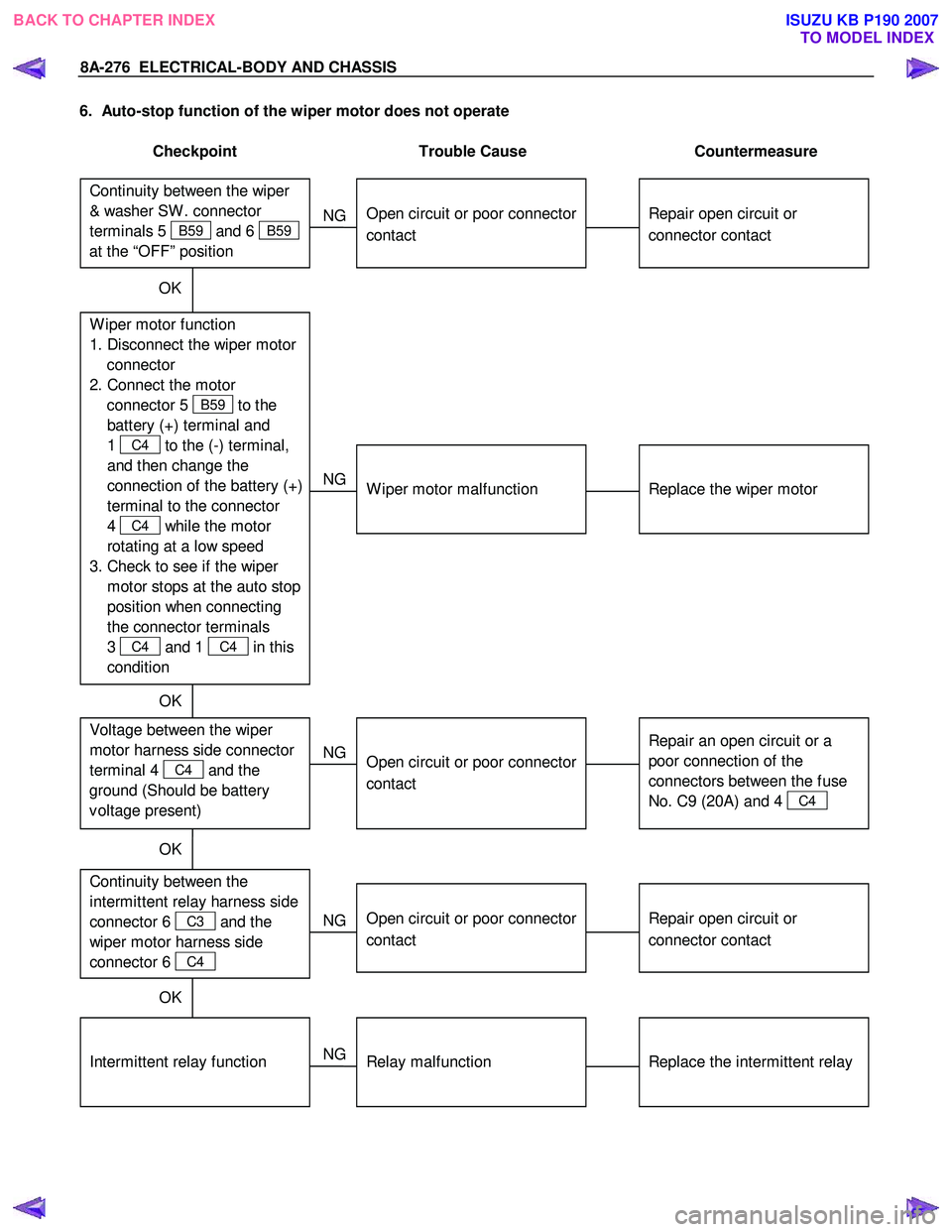
8A-274 ELECTRICAL-BODY AND CHASSIS
2. Wiper dose not operate at “ INT “ position
Checkpoint Trouble Cause Countermeasure
Replace the wiper & washer
SW .
SW . malfunction
NG
Repair grounding point contact
Grounding point
C36 (RHD),
C2 (LHD)
Poor grounding point contact
Repair open circuit or
connector contact
Voltage between the
intermittent relay harness side
connector terminal 4
C3
and the ground at the “INT”
position (Should be battery
voltage present)
Open circuit or poor connector
contact
NG
NG
OK
OK
Continuity between the wiper
& washer SW connector
terminals 4
B59 and 2 B59
at the “ INT “ position
Replace the intermittent relay
Intermittent relay function
Relay malfunction
NG
OK
3. Wiper does not operate at “LO” position
Replace the wiper motor
W iper motor function
1. Disconnect the wiper & washer SW . connector
2. Turn the starter SW . on
3. Short-circuit between the wiper & washer SW .
harness side connector terminal 3
B59 and
5
B59 .
4. Check to see if the wiper
motor rotates at a low
speed
W iper motor malfunction
NG
Replace the wiper & washer
SW .
W iper & washer SW . function
SW . malfunction
NG
OK
BACK TO CHAPTER INDEX TO MODEL INDEXISUZU KB P190 2007
Page 5214 of 6020

8A-276 ELECTRICAL-BODY AND CHASSIS
6. Auto-stop function of the wiper motor does not operate
Checkpoint Trouble Cause Countermeasure
Repair open circuit or
connector contact
Open circuit or poor connector
contact
NG
Repair open circuit or
connector contact
Open circuit or poor connector
contact
NG Continuity between the
intermittent relay harness side
connector 6
C3 and the
wiper motor harness side
connector 6
C4
Replace the intermittent relay
Relay malfunction
NG
Intermittent relay function
W iper motor function
1. Disconnect the wiper motor connector
2. Connect the motor connector 5
B59 to the
battery (+) terminal and
1
C4 to the (-) terminal,
and then change the
connection of the battery (+)
terminal to the connector
4
C4 while the motor
rotating at a low speed
3. Check to see if the wiper motor stops at the auto stop
position when connecting
the connector terminals
3
C4 and 1 C4 in this
condition
Continuity between the wiper
& washer SW . connector
terminals 5
B59 and 6 B59
at the “OFF” position
OK
Replace the wiper motor
W iper motor malfunction
NG
Repair an open circuit or a
poor connection of the
connectors between the fuse
No. C9 (20A) and 4
C4
Voltage between the wiper
motor harness side connector
terminal 4
C4 and the
ground (Should be battery
v oltage present)
Open circuit or poor connector
contact
NG
OK
OK
OK
BACK TO CHAPTER INDEX
TO MODEL INDEXISUZU KB P190 2007
Page 5215 of 6020

ELECTRICAL-BODY AND CHASSIS 8A-277
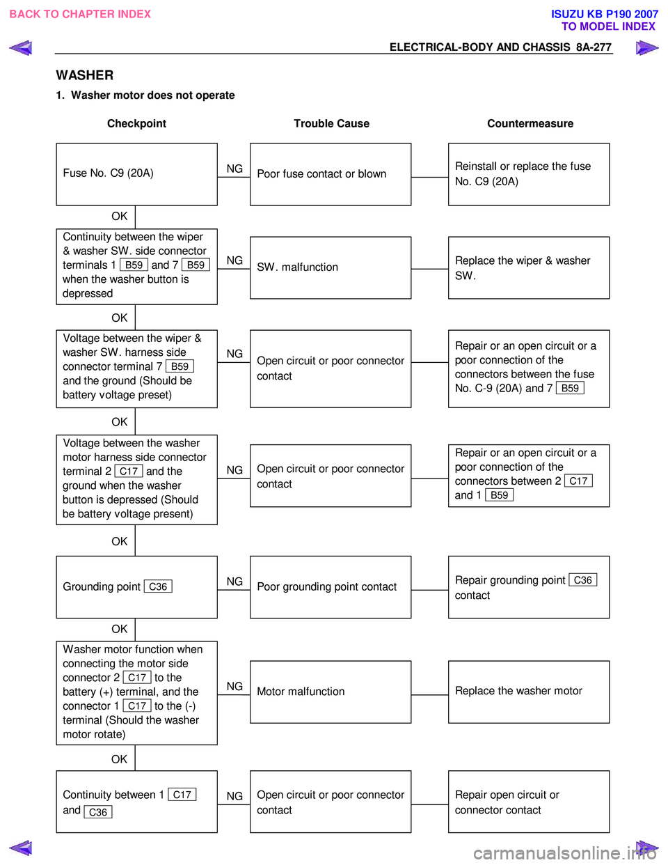
WASHER
1. Washer motor does not operate
Checkpoint Trouble Cause Countermeasure
Reinstall or replace the fuse
No. C9 (20A)
Poor fuse contact or blown
NG
Repair or an open circuit or a
poor connection of the
connectors between 2
C17
and 1
B59
Open circuit or poor connector
contact
NG Voltage between the washer
motor harness side connector
terminal 2
C17 and the
ground when the washer
button is depressed (Should
be battery v oltage present)
Repair grounding point
C36
contact
Poor grounding point contact
NG
Grounding point
C36
Replace the washer motor
Motor malfunction
NG
W asher motor function when
connecting the motor side
connector 2
C17 to the
battery (+) terminal, and the
connector 1
C17 to the (-)
terminal (Should the washer
motor rotate) OK
Repair open circuit or
connector contact
Open circuit or poor connector
contact
NG
Continuity between 1
C17
and
C36
OK
Continuity between the wiper
& washer SW . side connector
terminals 1
B59 and 7 B59
when the washer button is
depressed
Fuse No. C9 (20A)
OK
Replace the wiper & washer
SW .
SW . malfunction
NG
Repair or an open circuit or a
poor connection of the
connectors between the fuse
No. C-9 (20A) and 7
B59
Voltage between the wiper &
washer SW . harness side
connector terminal 7
B59
and the ground (Should be
battery v oltage preset)
Open circuit or poor connector
contact
NG
OK
OK
OK
BACK TO CHAPTER INDEX
TO MODEL INDEXISUZU KB P190 2007
Page 5282 of 6020

8A-344 ELECTRICAL-BODY AND CHASSIS
3. Speedometer pointer jumps erratically
Checkpoint Trouble Cause Countermeasure
Replace the vehicle speed
sensor, or repair an open
circuit in the circuit or a poor
connection at the connectors Vehicle speed sensor
malfunction, or open circuit or
poor connector contact
NG
Replace the meter assembly
Use meter tester to check the
speedometer function
Speedometer malfunction
NG
OK
Check the vehicle speed
sensor output by using the
oscilloscope
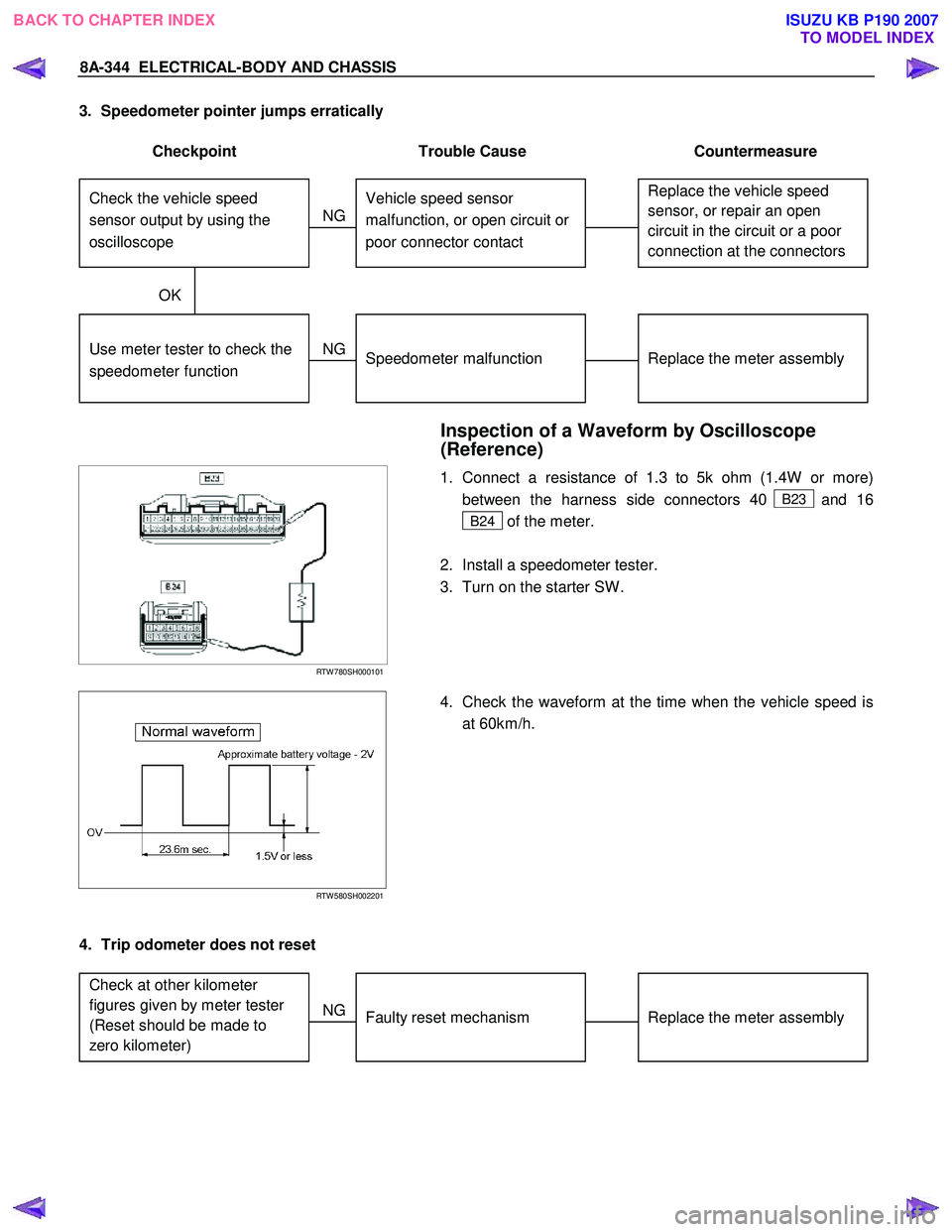
Inspection of a Waveform by Oscilloscope
(Reference)
RTW 780SH000101
1. Connect a resistance of 1.3 to 5k ohm (1.4W or more)
between the harness side connectors 40
B23 and 16
B24 of the meter.
2. Install a speedometer tester.
3. Turn on the starter SW .
RTW 580SH002201
4. Check the waveform at the time when the vehicle speed is
at 60km/h.
4. Trip odometer does not reset
Replace the meter assembly
Faulty reset mechanism
NG
Check at other kilometer
figures given by meter tester
(Reset should be made to
zero kilometer)
BACK TO CHAPTER INDEX
TO MODEL INDEXISUZU KB P190 2007