Page 5037 of 6020
ELECTRICAL-BODY AND CHASSIS 8A-99
TRANSMISSION HARNESS
RTW 78AXF035701
BACK TO CHAPTER INDEX TO MODEL INDEXISUZU KB P190 2007
Page 5078 of 6020
8A-140 ELECTRICAL-BODY AND CHASSIS
REMOVAL AND INSTALLATION
ECM (ENGINE CONTROL MODULE);
C24SE
Removal
1. Lift both the ECM harness connector locking levers and
remove the two harness connectors form the ECM.
2. Remove the four socket head screws securing the ECM to the mounting bracket.
3. Remove the ECM from the engine compartment .
4. Pull out the ECM.
5. Disconnect both red and tan connectors.
Refer to the Section 6E-ENGINE of this Manual.
IMPORTANT: The replacement ECM must be programmed.
“SPS (Service Programming System) and immobilizer
programming (if equipped) is/are necessary”
Installation
Follow the removal procedure in the reverse order to install the
ECM.
Pay close attention to the important points mentioned in the
following paragraphs.
Connector
Be absolutely sure that ECM is securely connected.
This will prevent a poor contact and open circuit.
BACK TO CHAPTER INDEX TO MODEL INDEXISUZU KB P190 2007
Page 5079 of 6020

ELECTRICAL-BODY AND CHASSIS 8A-141
REMOVAL AND INSTALLATION
ECM (ENGINE CONTROL MODULE);
4JH1-TC
Removal
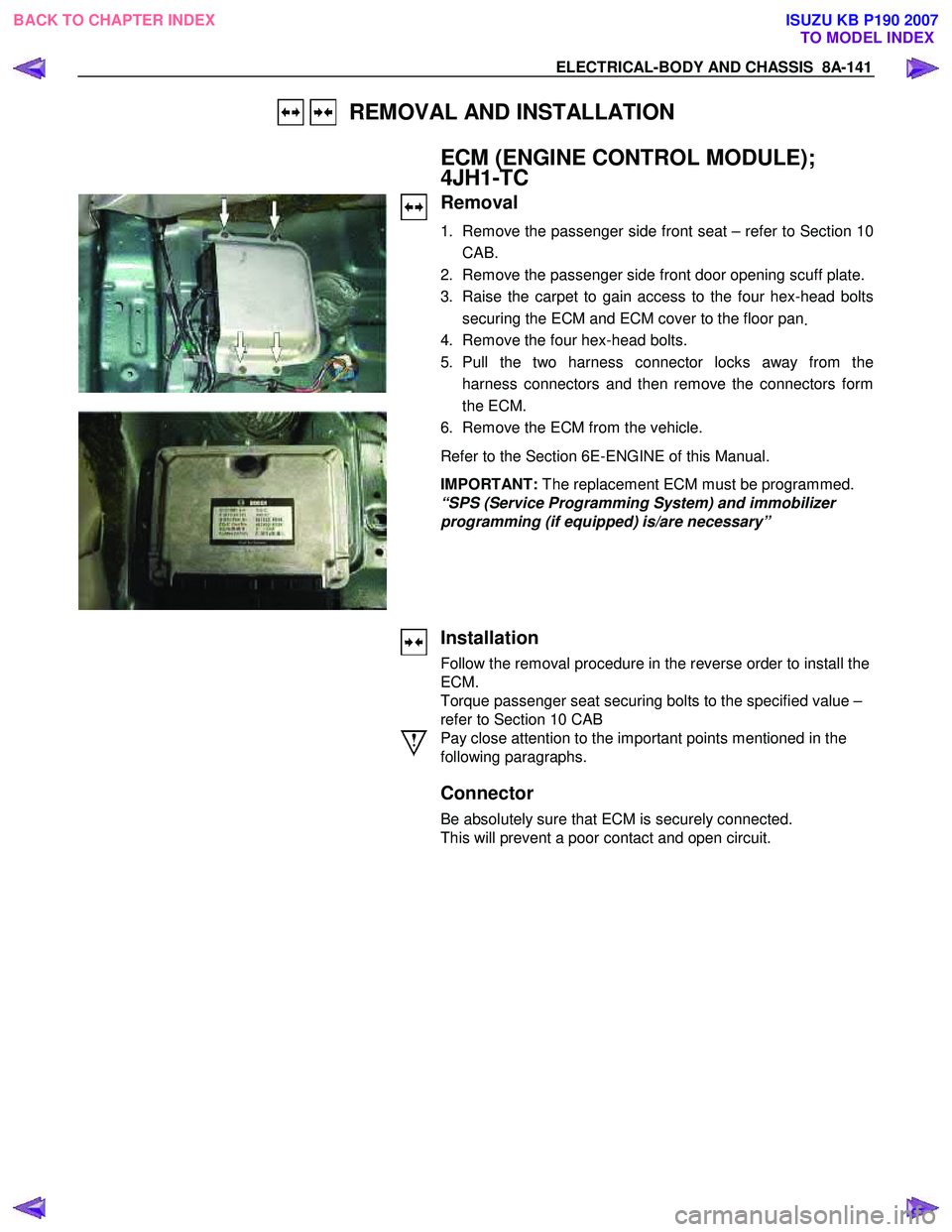
1. Remove the passenger side front seat – refer to Section 10
CAB.
2. Remove the passenger side front door opening scuff plate.
3. Raise the carpet to gain access to the four hex-head bolts securing the ECM and ECM cover to the floor pan .
4. Remove the four hex-head bolts.
5. Pull the two harness connector locks away from the harness connectors and then remove the connectors form
the ECM.
6. Remove the ECM from the vehicle.
Refer to the Section 6E-ENGINE of this Manual.
IMPORTANT: The replacement ECM must be programmed.
“SPS (Service Programming System) and immobilizer
programming (if equipped) is/are necessary”
Installation
Follow the removal procedure in the reverse order to install the
ECM.
Torque passenger seat securing bolts to the specified value –
refer to Section 10 CAB
Pay close attention to the important points mentioned in the
following paragraphs.
Connector
Be absolutely sure that ECM is securely connected.
This will prevent a poor contact and open circuit.
BACK TO CHAPTER INDEX TO MODEL INDEXISUZU KB P190 2007
Page 5107 of 6020

ELECTRICAL-BODY AND CHASSIS 8A-169
Installation
Follow the removal procedure in the reverse order to install the
headlight.
Pay close attention to the important points mentioned in the
following paragraphs.
Connector
Be absolutely sure that the headlight connector is securely
connected.
This will prevent a contact and an open circuit.
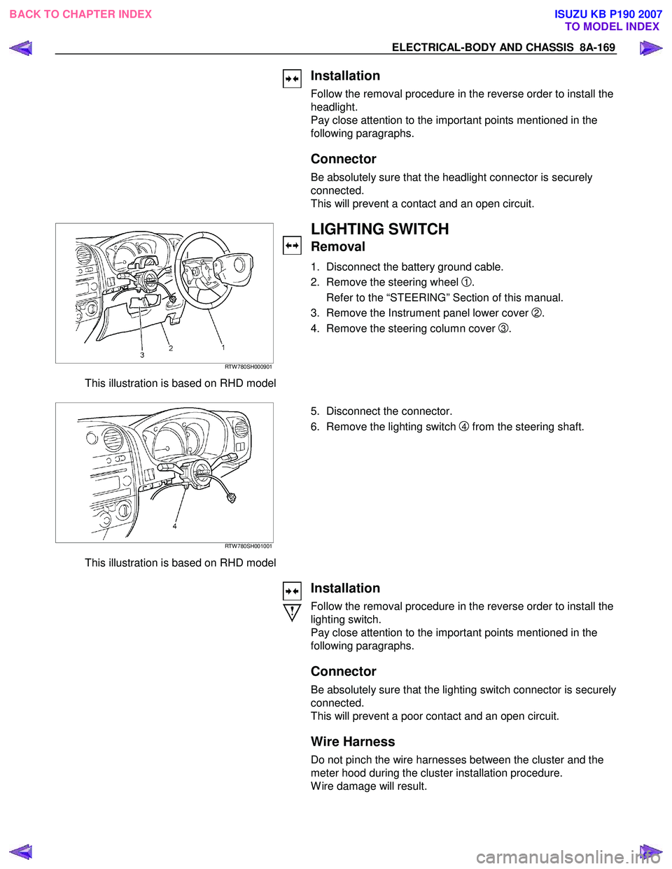
RTW 780SH000901
This illustration is based on RHD model
LIGHTING SWITCH
Removal
1. Disconnect the battery ground cable.
2. Remove the steering wheel
1.
Refer to the “STEERING” Section of this manual.
3. Remove the Instrument panel lower cover
2.
4. Remove the steering column cover
3.
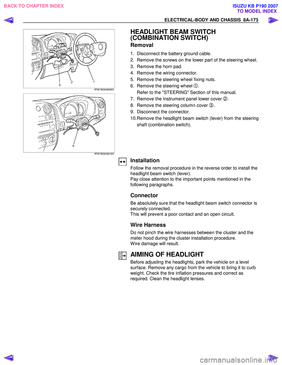
RTW 780SH001001
This illustration is based on RHD model
5. Disconnect the connector.
6. Remove the lighting switch
4 from the steering shaft.
Installation
Follow the removal procedure in the reverse order to install the
lighting switch.
Pay close attention to the important points mentioned in the
following paragraphs.
Connector
Be absolutely sure that the lighting switch connector is securely
connected.
This will prevent a poor contact and an open circuit.
Wire Harness
Do not pinch the wire harnesses between the cluster and the
meter hood during the cluster installation procedure.
W ire damage will result.
BACK TO CHAPTER INDEX TO MODEL INDEXISUZU KB P190 2007
Page 5108 of 6020
8A-170 ELECTRICAL-BODY AND CHASSIS
FRONT TURN SIGNAL LIGHT BULB
(A type)
Removal
HALOGEN STD TYPE RTW 78ASH000201
1. Turn the socket counterclockwise to disconnect it from the
front turn signal light housing.
2. Turn the bulb
1 counterclockwise to remove it.
1
HALOGEN PROJECTOR TYPE RTW 78ASH001001
FRONT COMBINATION LIGHT
ASSEMBLY (B type)
Removal
1. Open the bonnet.
RTW 580SH000901
2. Remove the bolt of front combination light assembly
3. Disconnect the front combination light harness connector.
4. Remove the front combination light assembly.
Installation
To install the front combination light assembly follow the
removal procedure in the reverse order.
Connector
Be absolutely sure that the front combination light harness
connector is correctly installed.
This will prevent a poor contact and an open circuit.
BACK TO CHAPTER INDEX TO MODEL INDEXISUZU KB P190 2007
Page 5111 of 6020

ELECTRICAL-BODY AND CHASSIS 8A-173
RTW 780SH000901
RTW 780SH001001
HEADLIGHT BEAM SWITCH
(COMBINATION SWITCH)
Removal
1. Disconnect the battery ground cable.
2. Remove the screws on the lower part of the steering wheel.
3. Remove the horn pad.
4. Remove the wiring connector.
5. Remove the steering wheel fixing nuts.
6. Remove the steering wheel
1.
Refer to the "STEERING" Section of this manual.
7. Remove the Instrument panel lower cover
2.
8. Remove the steering column cover
3.
9. Disconnect the connector.
10. Remove the headlight beam switch (lever) from the steering shaft (combination switch).
Installation
Follow the removal procedure in the reverse order to install the
headlight beam switch (lever).
Pay close attention to the important points mentioned in the
following paragraphs.
Connector
Be absolutely sure that the headlight beam switch connector is
securely connected.
This will prevent a poor contact and an open circuit.
Wire Harness
Do not pinch the wire harnesses between the cluster and the
meter hood during the cluster installation procedure.
W ire damage will result.
AIMING OF HEADLIGHT
Before adjusting the headlights, park the vehicle on a level
surface. Remove any cargo from the vehicle to bring it to curb
weight. Check the tire inflation pressures and correct as
required. Clean the headlight lenses.
BACK TO CHAPTER INDEX TO MODEL INDEXISUZU KB P190 2007
Page 5116 of 6020
8A-178 ELECTRICAL-BODY AND CHASSIS
INSPECTION AND REPAIR
Switch side Harness side
B60 B60
LIGHTING SWITCH
Lighting Switch Connections
Terminal
SW No.
position 3 2 1
OFF
Tail
Headlight
Switch side Harness side
B60 B60
HEADLIGHT BEAM SWITCH
Headlight Beam and Passing Switch
Connections
Terminal NO.
SW position 1 4
HI
At “Dimmer” position
LO
At “Passing” Position
BACK TO CHAPTER INDEX
TO MODEL INDEXISUZU KB P190 2007
Page 5126 of 6020
8A-188 ELECTRICAL-BODY AND CHASSIS
RTW 780SH000801
FOG LIGHT ADJUSTMENT (A type)
Vertical Adjustment
Turn the adjusting screw with a screwdriver to adjust the aim of
the fog light vertically.
FOG LIGHT ADJUSTMENT (B type)
Vertical Adjustment
Turn the adjusting screw with a screwdriver to adjust the aim of
the fog light vertically.
RTW 78ASH000401
FRONT FOG & REAR FOG SWITCH
RTW 48ASH000401
Inspection
Check to see if there is any continuity between the terminals of
the front fog light switch.
Replace the switch when the result of inspection is found
abnormal.
Removal
Preparation:
Disconnect the battery ground cable.
1. Ventilation grille
2. Harness connector
3. Front fog light & Rear fog light switch To remove the switch, push the lock from the back side of
the cluster assembly.
4. Remove the bulb.
BACK TO CHAPTER INDEX TO MODEL INDEXISUZU KB P190 2007