Page 3045 of 3061

WW-28
< SERVICE INFORMATION >
REAR WIPER AND WASHER SYSTEM
• through BCM terminal 55
• through BCM terminal 67
• through grounds M57, M61 and M79.
With output circuit 2 power and ground supplied the rear wiper motor operates in a clockwise sweep direction
until auto stop switch 2 closes (full sweep position). Auto stop switch 2 supplies ground
• to BCM terminal 26
• through rear wiper motor terminal 1
• through rear wiper motor terminal 3
• through grounds B117 and B132.
When the BCM receives this ground signal it turns off output circuit 2 and starts the timing function of 7 sec-
onds. After approximately 7 seconds the BCM turns on output circuit 1. This process repeats until the rear
wiper switch or ignition switch is turned off.
AUTO STOP OPERATION
When the rear wiper switch is turned off, the BCM will continue the cycle of output circuit 1 or output circuit 2
until auto stop switch 1 and auto stop switch 2 are both in the closed position. When the BCM receives ground
signals from auto stop switch 1 and auto stop switch 2 simultaneously, output circuit 1 and output circuit 2 are
both turned off.
REAR WASHER OPERATION
When the ignition switch is in the ON or START position, and the front and rear washer switches are OFF, the
front and rear washer motor is supplied power
• through 10A fuse (No. 9, located in the fuse block J/B)
• through combination switch (wiper switch) terminal 14
• through combination switch (wiper switch) terminal 11
• to front and rear washer motor terminal 2, and
• through combination switch (wiper switch) terminal 13
• to front and rear washer motor terminal 1.
When the rear wiper switch is in rear washer position, the BCM detects a rear washer signal by BCM wiper
switch reading function. Combination switch ground is supplied
• to front and rear washer motor terminal 1
• through combination switch (wiper switch) terminal 13
• through combination switch (wiper switch) terminal 12
• through grounds M57, M61 and M79.
With ground supplied, the front and rear washer motor is operated in the rear direction.
When the BCM detects that the rear washer motor has operated for 0.4 seconds or longer, BCM operates the
rear wiper motor.
When the BCM detects that the rear washer switch is in OFF, the rear wiper motor cycles approximately 3
times and then stops.
If the rear washer is operated with the rear wiper switch in the INT position, normal rear wiper operation will
take over. Once the rear washer switch is released the rear wiper will return to INT operation.
BCM Wiper Switch Reading Function
Refer to BCS-3, "System Description".
Page 3051 of 3061

WW-34
< SERVICE INFORMATION >
REAR WIPER AND WASHER SYSTEM
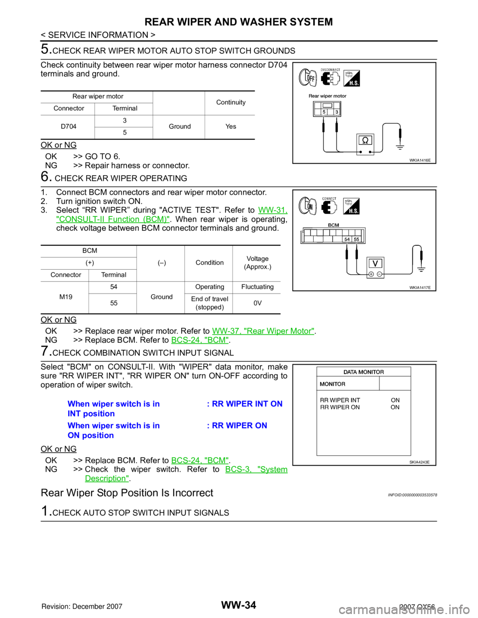
5.CHECK REAR WIPER MOTOR AUTO STOP SWITCH GROUNDS
Check continuity between rear wiper motor harness connector D704
terminals and ground.
OK or NG
OK >> GO TO 6.
NG >> Repair harness or connector.
6. CHECK REAR WIPER OPERATING
1. Connect BCM connectors and rear wiper motor connector.
2. Turn ignition switch ON.
3. Select “RR WIPER” during "ACTIVE TEST". Refer to WW-31,
"CONSULT-II Function (BCM)". When rear wiper is operating,
check voltage between BCM connector terminals and ground.
OK or NG
OK >> Replace rear wiper motor. Refer to WW-37, "Rear Wiper Motor".
NG >> Replace BCM. Refer to BCS-24, "
BCM".
7.CHECK COMBINATION SWITCH INPUT SIGNAL
Select "BCM" on CONSULT-II. With "WIPER" data monitor, make
sure "RR WIPER INT", "RR WIPER ON" turn ON-OFF according to
operation of wiper switch.
OK or NG
OK >> Replace BCM. Refer to BCS-24, "BCM".
NG >> Check the wiper switch. Refer to BCS-3, "
System
Description".
Rear Wiper Stop Position Is IncorrectINFOID:0000000003533578
1.CHECK AUTO STOP SWITCH INPUT SIGNALS
Rear wiper motor
Continuity
Connector Terminal
D7043
Ground Yes
5
WKIA1416E
BCM
(–) ConditionVo l ta g e
(Approx.) (+)
Connector Terminal
M1954
GroundOperating Fluctuating
55End of travel
(stopped)0V
WKIA1417E
When wiper switch is in
INT position: RR WIPER INT ON
When wiper switch is in
ON position: RR WIPER ON
SKIA4243E
Page 3053 of 3061

WW-36
< SERVICE INFORMATION >
REAR WIPER AND WASHER SYSTEM
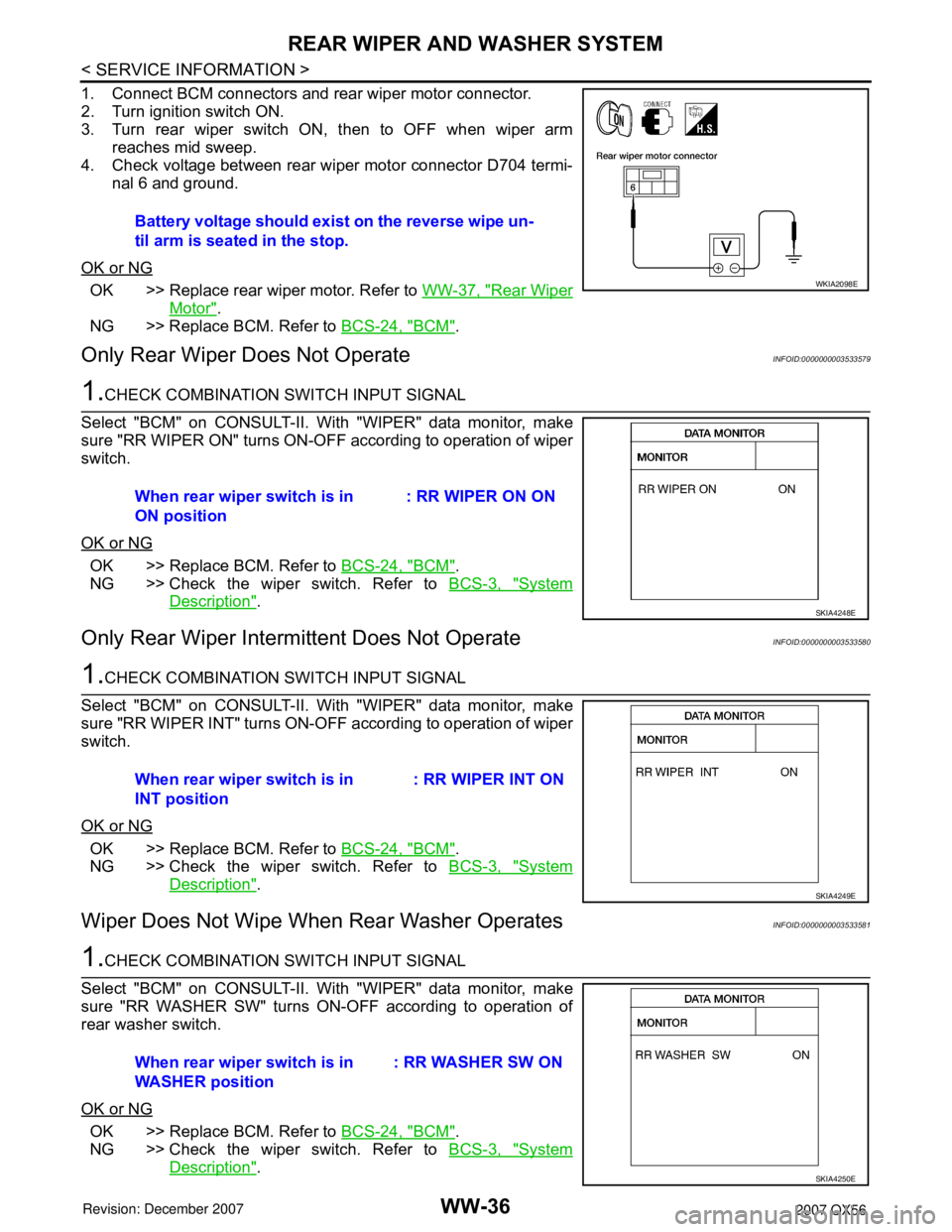
1. Connect BCM connectors and rear wiper motor connector.
2. Turn ignition switch ON.
3. Turn rear wiper switch ON, then to OFF when wiper arm
reaches mid sweep.
4. Check voltage between rear wiper motor connector D704 termi-
nal 6 and ground.
OK or NG
OK >> Replace rear wiper motor. Refer to WW-37, "Rear Wiper
Motor".
NG >> Replace BCM. Refer to BCS-24, "
BCM".
Only Rear Wiper Does Not OperateINFOID:0000000003533579
1.CHECK COMBINATION SWITCH INPUT SIGNAL
Select "BCM" on CONSULT-II. With "WIPER" data monitor, make
sure "RR WIPER ON" turns ON-OFF according to operation of wiper
switch.
OK or NG
OK >> Replace BCM. Refer to BCS-24, "BCM".
NG >> Check the wiper switch. Refer to BCS-3, "
System
Description".
Only Rear Wiper Intermittent Does Not OperateINFOID:0000000003533580
1.CHECK COMBINATION SWITCH INPUT SIGNAL
Select "BCM" on CONSULT-II. With "WIPER" data monitor, make
sure "RR WIPER INT" turns ON-OFF according to operation of wiper
switch.
OK or NG
OK >> Replace BCM. Refer to BCS-24, "BCM".
NG >> Check the wiper switch. Refer to BCS-3, "
System
Description".
Wiper Does Not Wipe When Rear Washer OperatesINFOID:0000000003533581
1.CHECK COMBINATION SWITCH INPUT SIGNAL
Select "BCM" on CONSULT-II. With "WIPER" data monitor, make
sure "RR WASHER SW" turns ON-OFF according to operation of
rear washer switch.
OK or NG
OK >> Replace BCM. Refer to BCS-24, "BCM".
NG >> Check the wiper switch. Refer to BCS-3, "
System
Description". Battery voltage should exist on the reverse wipe un-
til arm is seated in the stop.
WKIA2098E
When rear wiper switch is in
ON position: RR WIPER ON ON
SKIA4248E
When rear wiper switch is in
INT position: RR WIPER INT ON
SKIA4249E
When rear wiper switch is in
WASHER position: RR WASHER SW ON
SKIA4250E