2007 INFINITI QX56 wiper fluid
[x] Cancel search: wiper fluidPage 20 of 3061
![INFINITI QX56 2007 Factory Service Manual DESCRIPTION
ACS-7
< SERVICE INFORMATION >[ICC]
C
D
E
F
G
H
I
J
L
MA
B
ACS
N
O
P
Component DescriptionINFOID:0000000003533777
CAN CommunicationINFOID:0000000003533778
SYSTEM DESCRIPTION
Refer to LAN-4 INFINITI QX56 2007 Factory Service Manual DESCRIPTION
ACS-7
< SERVICE INFORMATION >[ICC]
C
D
E
F
G
H
I
J
L
MA
B
ACS
N
O
P
Component DescriptionINFOID:0000000003533777
CAN CommunicationINFOID:0000000003533778
SYSTEM DESCRIPTION
Refer to LAN-4](/manual-img/42/57029/w960_57029-19.png)
DESCRIPTION
ACS-7
< SERVICE INFORMATION >[ICC]
C
D
E
F
G
H
I
J
L
MA
B
ACS
N
O
P
Component DescriptionINFOID:0000000003533777
CAN CommunicationINFOID:0000000003533778
SYSTEM DESCRIPTION
Refer to LAN-4 .
Switch OperationINFOID:0000000003533779
The system is operated by a master ON/OFF switch and four control switches, all mounted on the steering
wheel.
ComponentVehicle-to-vehicle
distance control
modeConventional
(fixed speed)
cruise control
modeBrake assist
(with preview
brake)Description
ICC unit×××Controls vehicle speed through ECM via CAN
communication.
ICC sensor××Irradiate laser beam, and receives reflected la-
ser beam to measure distance from preceding
vehicle.
ECM×××Transmits throttle position signal and ICC steer-
ing switch signal to ICC unit.
ABS actuator and electric
unit (control unit)×××Transmits wheel speed signal to ICC unit. Oper-
ates brake booster based on CAN communica-
tion.
Brake pressure sensor××Detects fluid pressure in master cylinder.
Brake booster××Adjusts brake fluid pressure based on command
from ABS actuator and electric unit (control unit).
BCM×Transmit front wiper request signal to ICC unit.
TCM××Transmits gear position signal and output shaft
revolution signal to ICC unit.
No. Switch nameDescription
1 ACCEL/RES switch Resumes set speed or increases speed incrementally.
2 COAST/SET switch Sets desired cruise speed, reduces speed incrementally.
3 ON/OFF switch Master switch to activate the system.
SKIA5973E
Page 2108 of 3061
IDX-4
ALPHABETICAL INDEX
Duct and grilles .............................................. ATC-170
DVD - Wiring Diagram ....................................... AV-75
DVD Entertainment System ............................... AV-72
DVD Player ........................................................ AV-73
E
ECM input/output signal ..................... EC-109
, EC-133
ECM power supply ............................. EC-150, EC-475
ECM relay ........................................................ EC-150
ECM/PW - Wiring diagram ............................... EC-476
ECTS - Wiring diagram .................................... EC-220
Electric sunroof .................................................. RF-10
Electric throttle control actuator ......... EC-595, EC-606
Electrical load signal circuit .............................. EC-657
Electrical units location ...................................... PG-65
Electronic ignition (EI) system ........................... EC-27
Engine control circuit diagram ......................... EC-107
Engine control component parts location ........... EC-98
Engine control module (ECM) .......................... EC-479
Engine control system diagram ......................... EC-24
Engine coolant .................................................. CO-10
Engine coolant temperature sensor (ECTS) ... EC-218,
EC-231
Engine fail-safe system ...................................... EC-93
Engine oil ............................................................. LU-8
Engine oil filter replacement ............................. MA-17
Engine oil precautions .......................................... GI-7
Engine oil replacement ..................................... MA-17
Engine removal ................................................. EM-74
Engine room cover ............................................ EM-12
Engine serial number .......................................... GI-50
ETC1 - Wiring diagram .................................... EC-596
ETC2 - Wiring diagram .................................... EC-591
ETC3 - Wiring diagram .................................... EC-602
EVAP canister .................................................... EC-36
EVAP canister purge volume control solenoid valve ....
EC-395
, EC-403
EVAP canister vent control valve ....... EC-410, EC-417
EVAP control system (small leak) diagnosis .. EC-387,
EC-441
, EC-449
EVAP control system pressure sensor .... EC-424, EC-
427, EC-433
EVAP control system purge flow monitoring diagnosis
EC-382
EVAP vapor lines inspection ............................. MA-20
Evaporative emission (EVAP) system ............... EC-33
Evaporator ..................................................... ATC-186
Exhaust manifold .............................................. EM-21
Exhaust system ................................................... EX-3
Exhaust system inspection .................................. EX-3
Expansion valve ............................................. ATC-188
F
F/FOG - Wiring diagram ..................................... LT-56
F/PUMP - Wiring diagram ................................ EC-666
Final drive pre-inspection ................................. FFD-15
Final drive removal and installation .. FFD-12, RFD-13
Flow charts .......................................................... GI-27
Fluid temperature sensor (A/T) ........................ AT-123
Fluids ................................................................ MA-11
Fluorescent leak detector .............................. ATC-189
Fog lamp, front ................................................... LT-54
Fog lamp, front, removal and installation ........... LT-62
Foot lamp ......................................................... LT-111
Freeze frame data ............................... EC-55, EC-121
Front brake solenoid valve ................. AT-139, AT-141
Front bumper ...................................................... EI-13
Front case (Transfer) .......................... TF-149, TF-176
Front combination lamp removal and installation LT-25
Front door ............................. BL-117, BL-121, GW-62
Front Door Trim ................................................... EI-32
Front drive shaft (Transfer) ................. TF-149, TF-176
Front fog lamp .................................................... LT-54
Front fog lamp removal and installation ............. LT-62
Front passenger air bag .................................. SRS-43
Front seat ........................................................... SE-89
Front seat belt ...................................................... SB-3
Front seat belt pre-tensioner ............... SRS-3, SRS-50
Front washer ...................................................... WW-4
Front wiper ......................................................... WW-4
FTS - Wiring diagram ....................................... AT-124
FTTS - Wiring diagram ...................... EC-334, EC-339
Fuel cut control (at no load high engine speed) EC-28
Fuel filter replacement ......................................... FL-5
Fuel gauge ............................................................ DI-5
Fuel injection system (Bank 1) .......... EC-311, EC-322
Fuel injection system (Bank 2) .......... EC-311, EC-322
Fuel injector .................................................... EC-659
Fuel injector and fuel tube ................................. EM-31
Fuel level sensor ................. EC-458, EC-460, EC-462
Fuel line inspection .............................................. FL-4
Fuel precautions ................................................... GI-5
Fuel pressure check .......................................... EC-82
Fuel pressure release ....................................... EC-82
Fuel pump ....................................................... EC-665
Fuel pump and gauge .......................................... FL-5
Fuel system .......................................................... FL-4
Fuel tank ............................................................ FL-10
Fuel tank temperature sensor ........... EC-332, EC-338
Fuel tank vacuum relief valve ........................... EC-36
FUELB1 - Wiring diagram ................. EC-313, EC-324
FUELB2 - Wiring diagram ................. EC-315, EC-326
Fuse ...................................................... PG-17, PG-77
Fuse and fusible link box .................................. PG-77
Fuse block ......................................................... PG-76
Fusible link ............................................ PG-17, PG-77
G
Garage jack and safety stand ............................. GI-42
Gauges ................................................................. DI-5
Generator .......................................................... SC-17
Generic scan tool (GST) ................................. EC-131
Glass ...................................... GW-11, GW-62, GW-65
Glove box lamp ................................................ LT-131
GPS antenna ..................................................... AV-82
Page 2112 of 3061
IDX-8
ALPHABETICAL INDEX
Three way catalyst ............................................ EM-21
Three way catalyst function (Bank 1) ............... EC-376
Three way catalyst function (Bank 2) ............... EC-376
Three way catalyst precautions ............................ GI-5
Throttle control motor ....................................... EC-601
Throttle control motor relay .............................. EC-589
Throttle position sensor (TPS) .. EC-224, EC-343, EC-
514, EC-516, EC-621
Throttle valve closed position learning ............... EC-80
Tie-rod ............................................................... PS-15
Timing chain ..................................................... EM-37
Tire rotation ....................................................... MA-28
Tire size .............................................................. GI-51
Torque converter installation AT-239, AT-240, AT-243,
AT-244
Torque convertor clutch solenoid valve ... AT-114, AT-
116
Tow truck towing ................................................. GI-44
Towing point ....................................................... GI-45
TPS1 - Wiring diagram .................................... EC-345
TPS2 - Wiring diagram .................................... EC-226
TPS3 - Wiring diagram .................................... EC-623
Traction control system - Wiring diagram ....... BRC-16
Transfer control device ............. TF-75, TF-79, TF-138
Transfer control unit inspection table ................. TF-35
Transfer dropping resistor .................................. TF-89
Transfer fluid temperature sensor TF-103, TF-154, TF-
167
Transfer motor .................................... TF-101, TF-142
Transfer motor relay ........................................ TF-101
Transfer oil replacement ................................... MA-24
Transfer serial number ........................................ GI-50
Transmission serial number ................................ GI-50
Tread-FR&RR (Dimensions) ............................... GI-51
Trim ..................................................................... EI-35
TRNSCV - Wiring diagram .................. BL-130, BL-146
Trouble diagnoses .............................................. GI-11
Turbine revolution sensor ................................ AT-105
TURN - Wiring diagram ...................................... LT-67
Turn signal lamp ................................................. LT-63
Two trip detection logic ...................................... EC-49
Two-pole lift ........................................................ GI-43
V
Vacuum hose (brake system) ............................ BR-20
Vacuum hose drawing (Engine control) ........... EC-106
Valve clearance ................................................ EM-55
Valve guide ....................................................... EM-69
Vanity mirror lamp ............................................. LT-110
VDC (vehicle dynamics control) ........................ BRC-7
VDC -Wiring diagram ...................................... BRC-16
Vehicle identification number .............................. GI-49
Vehicle recovery (freeing a stuck vehicle) .......... GI-45
Vehicle security (theft warning) system ............. BL-67
Vehicle speed sensor (VSS) ............................ EC-464
VEHSEC - Wiring diagram ................................. BL-71
VENT/V - Wiring diagram .................. EC-412, EC-419
VIN registration .................................................. EC-79
Viscosity number (SAE) .................................... MA-12
VSS A/T - Wiring diagram .................. AT-107, AT-109
W
W/ANT - Wiring diagram .................................... AV-59
Wait detection switch ......................................... TF-68
WARN - Wiring diagram ...................................... DI-29
Warning chime .................................................... DI-38
Warning lamps .................................................... DI-28
Washer, front ..................................................... WW-4
Washer, rear .................................................... WW-29
Water pump ...................................................... CO-19
Water temperature gauge ..................................... DI-5
Wheel alignment (front) ..................................... FSU-6
Wheel alignment (rear) ................................... RSU-25
Wheel bearing (front) ........................................ FAX-5
Wheel bearing (rear) ......................................... RAX-5
Wheel hub (rear) ............................................... RAX-5
Wheel size .......................................................... GI-51
Wheelbase (Dimensions) .................................... GI-51
Width (Dimensions) ............................................. GI-51
WINDOW - Wiring diagram .............................. GW-22
Window, door ...................................... GW-62, GW-65
Windshield ....................................................... GW-11
WIP/R - Wiring diagram ................................... WW-33
WIPER - Wiring diagram .................................... WW-8
Wiper, front ........................................................ WW-4
Wiper, rear ....................................................... WW-29
Wiring Diagram (Cell code) list ......................... PG-62
Wiring diagrams .................................................. GI-15
WT-T/WARN - Wiring diagram .......................... WT-11
Page 2176 of 3061
![INFINITI QX56 2007 Factory Service Manual TROUBLE DIAGNOSIS
LAN-45
< SERVICE INFORMATION >[CAN]
C
D
E
F
G
H
I
J
L
MA
B
LAN
N
O
P
Engine speed signal T R R R R R R
Engine status signal T R
Fuel consumption monitor signalTR
RT
ICC steering swit INFINITI QX56 2007 Factory Service Manual TROUBLE DIAGNOSIS
LAN-45
< SERVICE INFORMATION >[CAN]
C
D
E
F
G
H
I
J
L
MA
B
LAN
N
O
P
Engine speed signal T R R R R R R
Engine status signal T R
Fuel consumption monitor signalTR
RT
ICC steering swit](/manual-img/42/57029/w960_57029-2175.png)
TROUBLE DIAGNOSIS
LAN-45
< SERVICE INFORMATION >[CAN]
C
D
E
F
G
H
I
J
L
MA
B
LAN
N
O
P
Engine speed signal T R R R R R R
Engine status signal T R
Fuel consumption monitor signalTR
RT
ICC steering switch signal T R
Malfunction indicator lamp signal T R
Wide open throttle position signal T R
A/T CHECK indicator lamp signal T R
A/T fluid temperature sensor signal T R
A/T position indicator lamp signal T R R
A/T self-diagnosis signal R T
Current gear position signal T R R
Output shaft revolution signal R T R
P range signal T R R R R
Turbine revolution signal R T R
ICC sensor signal T R
Buzzer output signalTR
TR
ICC OD cancel request signal R R T
ICC operation signal R R T
ICC system display signal T R
System setting signalTR
RT
A/C switch signal R T R
Blower fan motor switch signal R T
Day time running light request signal T R R
Door switch signal R T R R R
Front fog light request signal T R
Front wiper request signal R T R
High beam request signal T R R
Horn chirp signal T R
Ignition switch signal R T R
Key fob door unlock signal R T
Key fob ID signal R T
Key switch signal R T
Low beam request signal T R
Position light request signal T R R
Rear window defogger switch signal T R R
Sleep wake up signal R T R R
Theft warning horn request signal T R
Tire pressure data signal T R
Tire pressure signal T R R
Turn indicator signal T RSignal name/Connecting unit
ECM
TCM
LASER
ICC
ADP
BCM
DISP
HVAC
M&A
STRG
ABS
IPDM-E
Page 2178 of 3061
![INFINITI QX56 2007 Factory Service Manual TROUBLE DIAGNOSIS
LAN-47
< SERVICE INFORMATION >[CAN]
C
D
E
F
G
H
I
J
L
MA
B
LAN
N
O
P
Cooling fan speed request signal TR
Engine coolant temperature signal T R R
Engine speed signal T R R R R R R R
E INFINITI QX56 2007 Factory Service Manual TROUBLE DIAGNOSIS
LAN-47
< SERVICE INFORMATION >[CAN]
C
D
E
F
G
H
I
J
L
MA
B
LAN
N
O
P
Cooling fan speed request signal TR
Engine coolant temperature signal T R R
Engine speed signal T R R R R R R R
E](/manual-img/42/57029/w960_57029-2177.png)
TROUBLE DIAGNOSIS
LAN-47
< SERVICE INFORMATION >[CAN]
C
D
E
F
G
H
I
J
L
MA
B
LAN
N
O
P
Cooling fan speed request signal TR
Engine coolant temperature signal T R R
Engine speed signal T R R R R R R R
Engine status signal T R
Fuel consumption monitor signalTR
RT
ICC steering switch signal T R
Malfunction indicator lamp signal T R
Wide open throttle position signal T R
A/T CHECK indicator lamp signal T R
A/T fluid temperature sensor signal T R
A/T position indicator lamp signal T R R R
A/T self-diagnosis signal R T
Current gear position signal T R R
Output shaft revolution signal R T R R
P range signal T R R R R
Turbine revolution signal R T R
ICC sensor signal T R
Buzzer output signalTR
TR
ICC OD cancel request signal R R T
ICC operation signal R R T
ICC system display signal T R
System setting signalTR
RT
A/C switch signal R T R
Blower fan motor switch signal R T
Day time running light request signal T R R
Door switch signal R T R R R
Front fog light request signal T R
Front wiper request signal R T R
High beam request signal T R R
Horn chirp signal T R
Ignition switch signal R T R
Key fob door unlock signal R T
Key fob ID signal R T
Key switch signal R T
Low beam request signal T R
Position light request signal T R R
Rear window defogger switch signal T R R
Sleep wake up signal R T R R
Theft warning horn request signal T R
Tire pressure data signal T RSignal name/Connecting unit
ECM
TCM
LASER
ICC
ADP
BCM
DISP
HVAC
M&A
STRG
4WD
ABS
IPDM-E
Page 3018 of 3061
WW-1
ELECTRICAL
C
D
E
F
G
H
I
J
L
M
SECTION WW
A
B
WW
N
O
P
CONTENTS
WIPER, WASHER & HORN
SERVICE INFORMATION ............................2
PRECAUTION .....................................................2
Precaution for Supplemental Restraint System
(SRS) "AIR BAG" and "SEAT BELT PRE-TEN-
SIONER" ...................................................................
2
FRONT WIPER AND WASHER SYSTEM ..........3
Component Parts and Harness Connector Loca-
tion ............................................................................
3
System Description ...................................................3
CAN Communication System Description .................5
Schematic .................................................................6
Wiring Diagram - WIPER - ........................................7
Terminal and Reference Value for BCM ...................9
Terminal and Reference Value for IPDM E/R ...........9
Work Flow ...............................................................10
Preliminary Check ...................................................10
CONSULT-II Function (BCM) ..................................11
CONSULT-II Function (IPDM E/R) ..........................12
Front Wiper Does Not Operate ...............................13
Front Wiper Arms ....................................................21
Wiper Motor and Linkage ........................................22
Washer Nozzle Adjustment .....................................23
Washer Tube Layout ...............................................23
Wiper and Washer Switch .......................................23
Washer Fluid Reservoir ...........................................24
Washer Motor ..........................................................24
REAR WIPER AND WASHER SYSTEM ...........26
Component Parts and Harness Connector Loca-
tion ..........................................................................
26
System Description ..................................................26
Wiring Diagram - WIP/R - ........................................29
Terminal and Reference Value for BCM ..................30
How to Proceed with Trouble Diagnosis ..................30
Preliminary Check ...................................................31
CONSULT-II Function (BCM) ..................................31
Rear Wiper Does Not Operate ................................33
Rear Wiper Stop Position Is Incorrect .....................34
Only Rear Wiper Does Not Operate ........................36
Only Rear Wiper Intermittent Does Not Operate .....36
Wiper Does Not Wipe When Rear Washer Oper-
ates ..........................................................................
36
Rear Wiper Arm .......................................................37
Rear Wiper Motor ....................................................37
Rear Washer Nozzle Adjustment ............................38
Rear Washer Tube Layout ......................................39
Rear Washer Nozzle ...............................................39
Rear Wiper and Washer Switch ..............................39
Washer Fluid Reservoir ...........................................40
Washer Motor ..........................................................40
POWER SOCKET .............................................41
Wiring Diagram - P/SCKT - .....................................41
Front Power Socket LH, Rear Cargo Power Sock-
et ..............................................................................
41
Front Power Socket RH (For Cigarette Lighter),
Console Power Socket ............................................
42
HORN ................................................................43
Wiring Diagram - HORN - ........................................43
Removal and Installation .........................................43
Page 3020 of 3061
FRONT WIPER AND WASHER SYSTEM
WW-3
< SERVICE INFORMATION >
C
D
E
F
G
H
I
J
L
MA
B
WW
N
O
P
FRONT WIPER AND WASHER SYSTEM
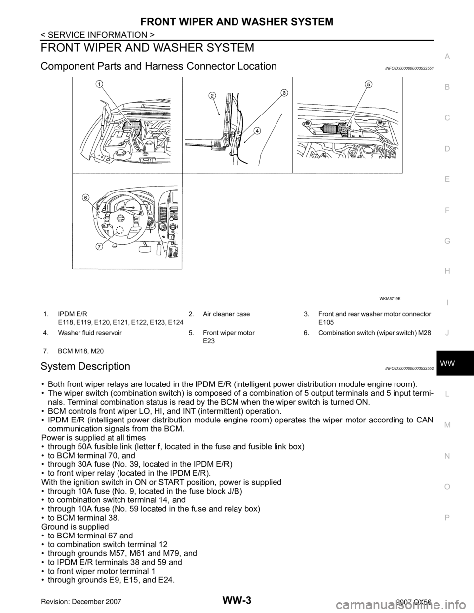
Component Parts and Harness Connector LocationINFOID:0000000003533551
System DescriptionINFOID:0000000003533552
• Both front wiper relays are located in the IPDM E/R (intelligent power distribution module engine room).
• The wiper switch (combination switch) is composed of a combination of 5 output terminals and 5 input termi-
nals. Terminal combination status is read by the BCM when the wiper switch is turned ON.
• BCM controls front wiper LO, HI, and INT (intermittent) operation.
• IPDM E/R (intelligent power distribution module engine room) operates the wiper motor according to CAN
communication signals from the BCM.
Power is supplied at all times
• through 50A fusible link (letter f, located in the fuse and fusible link box)
• to BCM terminal 70, and
• through 30A fuse (No. 39, located in the IPDM E/R)
• to front wiper relay (located in the IPDM E/R).
With the ignition switch in ON or START position, power is supplied
• through 10A fuse (No. 9, located in the fuse block J/B)
• to combination switch terminal 14, and
• through 10A fuse (No. 59 located in the fuse and relay box)
• to BCM terminal 38.
Ground is supplied
• to BCM terminal 67 and
• to combination switch terminal 12
• through grounds M57, M61 and M79, and
• to IPDM E/R terminals 38 and 59 and
• to front wiper motor terminal 1
• through grounds E9, E15, and E24.
WKIA5719E
1. IPDM E/R
E118, E119, E120, E121, E122, E123, E1242. Air cleaner case 3. Front and rear washer motor connector
E105
4. Washer fluid reservoir 5. Front wiper motor
E236. Combination switch (wiper switch) M28
7. BCM M18, M20
Page 3040 of 3061
FRONT WIPER AND WASHER SYSTEM
WW-23
< SERVICE INFORMATION >
C
D
E
F
G
H
I
J
L
MA
B
WW
N
O
P
4. Install cowl top. Refer to EI-17.
5. Ensure that wiper blades stop within proper clearance. Refer to WW-21, "
Front Wiper Arms".
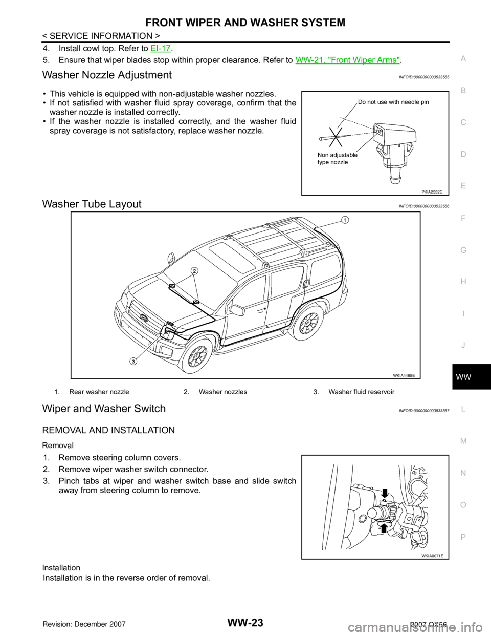
Washer Nozzle AdjustmentINFOID:0000000003533565
• This vehicle is equipped with non-adjustable washer nozzles.
• If not satisfied with washer fluid spray coverage, confirm that the
washer nozzle is installed correctly.
• If the washer nozzle is installed correctly, and the washer fluid
spray coverage is not satisfactory, replace washer nozzle.
Washer Tube LayoutINFOID:0000000003533566
Wiper and Washer SwitchINFOID:0000000003533567
REMOVAL AND INSTALLATION
Removal
1. Remove steering column covers.
2. Remove wiper washer switch connector.
3. Pinch tabs at wiper and washer switch base and slide switch
away from steering column to remove.
Installation
Installation is in the reverse order of removal.
PKIA2552E
WKIA4465E
1. Rear washer nozzle 2. Washer nozzles 3. Washer fluid reservoir
WKIA0071E