2007 INFINITI QX56 power steering
[x] Cancel search: power steeringPage 1601 of 3061
EC-518
< SERVICE INFORMATION >
DTC P1564 ASCD STEERING SWITCH
• Combination switch (spiral cable)
• Harness for open and short between ECM and combination switch
>> Repair open circuit or short to ground or short to power in harness or connectors.
7.CHECK ASCD STEERING SWITCH
Refer to EC-518, "
Component Inspection".
OK or NG
OK >> GO TO 8.
NG >> Replace ASCD steering switch. Refer to PS-13, "
Disassembly and Assembly".
8.CHECK INTERMITTENT INCIDENT
Refer to EC-138
.
>>INSPECTION END
Component InspectionINFOID:0000000003532052
ASCD STEERING SWITCH
1. Disconnect combination switch (spiral cable) harness connector M102.
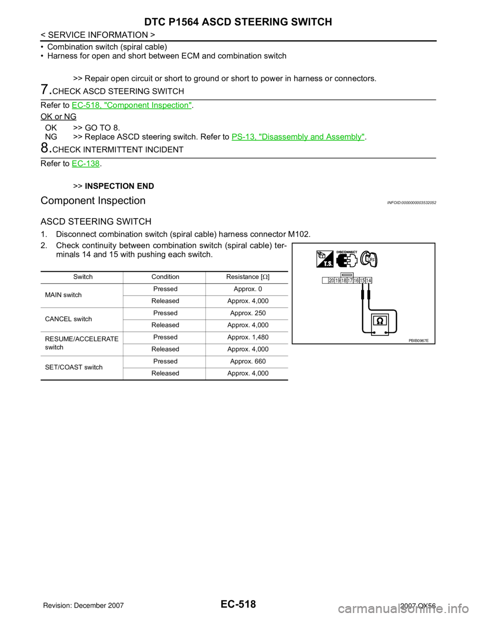
2. Check continuity between combination switch (spiral cable) ter-
minals 14 and 15 with pushing each switch.
Switch Condition Resistance [Ω]
MAIN switchPressed Approx. 0
Released Approx. 4,000
CANCEL switchPressed Approx. 250
Released Approx. 4,000
RESUME/ACCELERATE
switchPressed Approx. 1,480
Released Approx. 4,000
SET/COAST switchPressed Approx. 660
Released Approx. 4,000
PBIB0967E
Page 1783 of 3061
DRIVE BELTSEM-13
< SERVICE INFORMATION >
C
DE
F
G H
I
J
K L
M A
EM
NP
O
DRIVE BELTS
Checking Drive BeltsINFOID:0000000003531521
WARNING:
Be sure to perform when the engine is stopped.
1. Remove air duct and resonator assembly when inspecting drive belt.
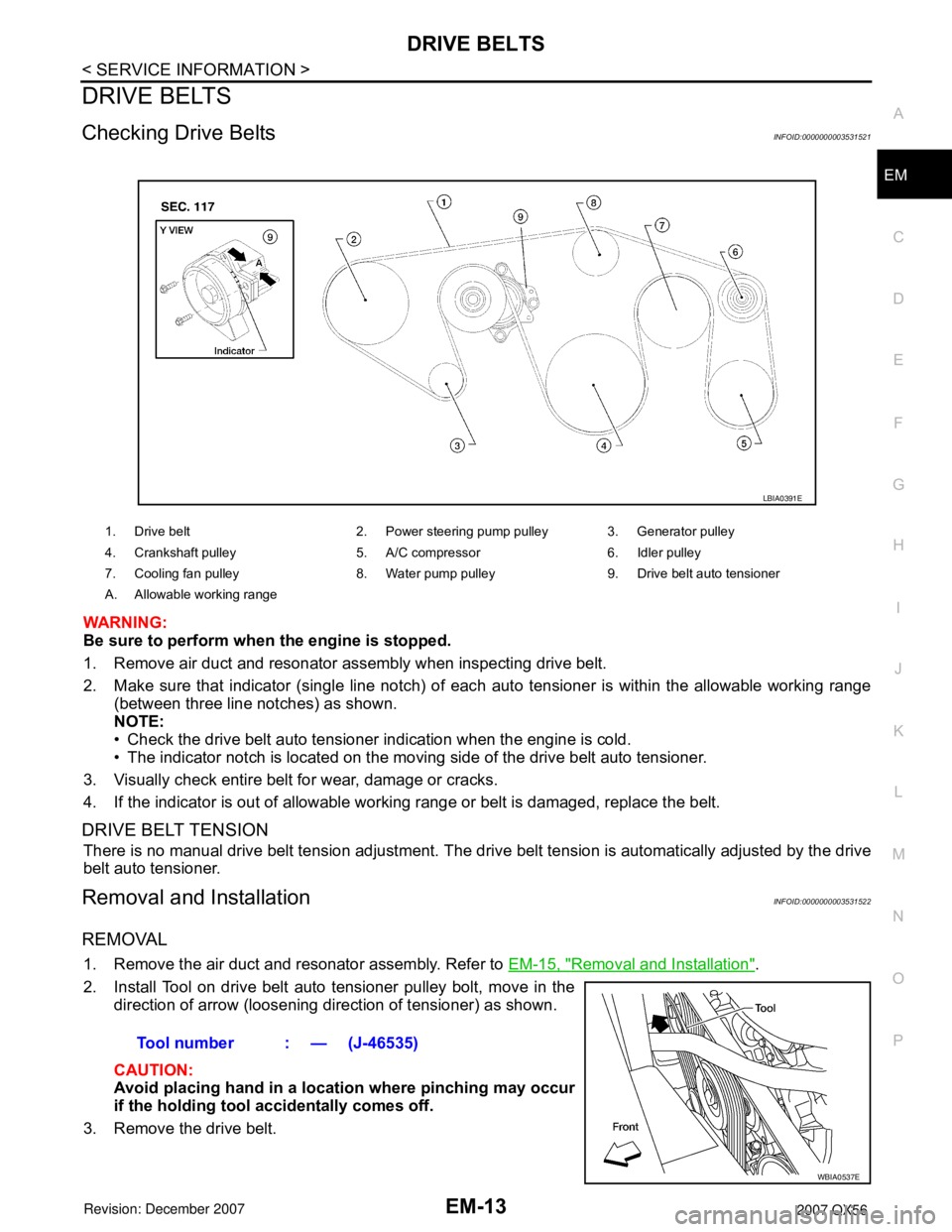
2. Make sure that indicator (single line notch) of eac
h auto tensioner is within the allowable working range
(between three line notches) as shown.
NOTE:
• Check the drive belt auto tensioner indication when the engine is cold.
• The indicator notch is located on the moving side of the drive belt auto tensioner.
3. Visually check entire belt for wear, damage or cracks.
4. If the indicator is out of allowable work ing range or belt is damaged, replace the belt.
DRIVE BELT TENSION
There is no manual drive belt tension adjustment. The driv e belt tension is automatically adjusted by the drive
belt auto tensioner.
Removal and InstallationINFOID:0000000003531522
REMOVAL
1. Remove the air duct and resonator assembly. Refer to EM-15, "Removal and Installation".
2. Install Tool on drive belt auto tensioner pulley bolt, move in the direction of arrow (loosening direction of tensioner) as shown.
CAUTION:
Avoid placing hand in a locat ion where pinching may occur
if the holding tool accidentally comes off.
3. Remove the drive belt.
1. Drive belt 2. Power steering pump pulley 3. Generator pulley
4. Crankshaft pulley 5. A/C compressor 6. Idler pulley
7. Cooling fan pulley 8. Water pump pulley 9. Drive belt auto tensioner
A. Allowable working range
LBIA0391E
Tool number : — (J-46535)
WBIA0537E
Page 1808 of 3061
EM-38
< SERVICE INFORMATION >
TIMING CHAIN
Removal and Installation
INFOID:0000000003531533
NOTE:
• To remove timing chain and associated parts, start with those on the LH bank. The procedure for removing parts on the RH bank is omitted because it is the same as that for removal on the LH bank.
• To install timing chain and associated parts, start with those on the RH bank. The procedure for installing parts on the LH bank is omitted because it is t he same as that for installation on the RH bank.
REMOVAL
1. Remove the engine assembly from the vehicle. Refer to EM-74, "Removal and Installation".
2. Remove the following components and related parts: • Drive belt auto tensioner and idler pulley. Refer to EM-13, "
Removal and Installation".
• Thermostat housing and water hose. Refer to CO-20, "
Removal and Installation".
• Power steering oil pump bracket. Refer to LU-14, "
Removal and Installation".
• Oil pan (lower), (upper) and oil strainer. Refer to EM-24, "
Removal and Installation".
• Ignition coil. Refer to EM-28, "
Removal and Installation".
• Rocker cover. Refer to EM-35, "
Removal and Installation".
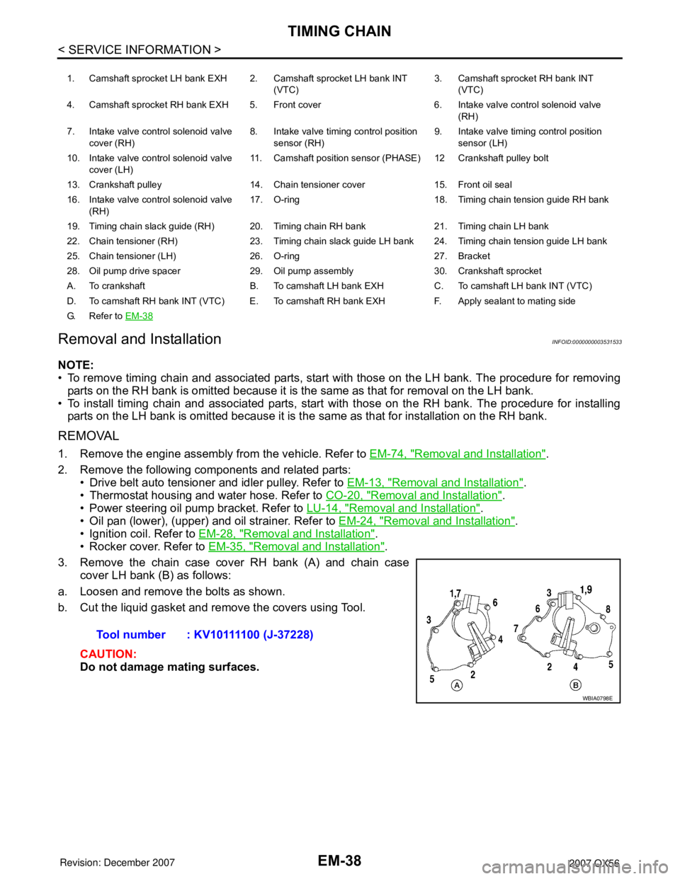
3. Remove the chain case cover RH bank (A) and chain case cover LH bank (B) as follows:
a. Loosen and remove the bolts as shown.
b. Cut the liquid gasket and remove the covers using Tool.
CAUTION:
Do not damage mating surfaces.
1. Camshaft sprocket LH bank EXH 2. Camshaft sprocket LH bank INT (VTC)3. Camshaft sprocket RH bank INT
(VTC)
4. Camshaft sprocket RH bank EXH 5. Front cover 6. Intake valve control solenoid valve (RH)
7. Intake valve control solenoid valve cover (RH) 8. Intake valve timing control position
sensor (RH) 9. Intake valve timing control position
sensor (LH)
10. Intake valve control solenoid valve cover (LH) 11. Camshaft position sensor (PHASE) 12 Crankshaft pulley bolt
13. Crankshaft pulley 14. Chain tensioner cover 15. Front oil seal
16. Intake valve control solenoid valve (RH) 17. O-ring 18. Timing chain tension guide RH bank
19. Timing chain slack guide (RH) 20. Timing chain RH bank 21. Timing chain LH bank
22. Chain tensioner (RH) 23. Timing chain slack guide LH bank 24. Timing chain tension guide LH bank
25. Chain tensioner (LH) 26. O-ring 27. Bracket
28. Oil pump drive spacer 29. Oil pump assembly 30. Crankshaft sprocket
A. To crankshaft B. To camshaft LH bank EXH C. To camshaft LH bank INT (VTC)
D. To camshaft RH bank INT (VTC) E. To camshaft RH bank EXH F. Apply sealant to mating side
G. Refer to EM-38
Tool number : KV10111100 (J-37228)
WBIA0798E
Page 1845 of 3061
ENGINE ASSEMBLY
EM-75
< SERVICE INFORMATION >
C
D
E
F
G
H
I
J
K
L
MA
EM
N
P O
6. Remove the engine room cover using power tools.
7. Remove the air duct and air cleaner case assembly. Refer to EM-15, "
Removal and Installation".
8. Disconnect the vacuum hose between the vehicle and engine and set it aside.
9. Remove the radiator assembly and hoses. Refer to CO-13, "
Removal and Installation".
10. Remove the drive belts. Refer to EM-15, "
Removal and Installation".
11. Remove the fan blade. Refer to CO-16, "
Removal and Installation (Crankshaft Driven Type)".
12. Disconnect the engine room harness from the fuse box and set it aside.
13. Disconnect the ECM.
14. Disconnect the engine room harness from the engine side and set it aside.
15. Disconnect the engine harness grounds.
16. Disconnect the power steering reservoir tank from the engine and move it aside.
17. Disconnect the power steering oil pump from the engine. Move it aside and secure it using suitable wire or
rope. Refer to PS-21, "
Removal and Installation".
18. Remove the A/C compressor bolts and set the compressor aside. Refer to ATC-154, "
Removal and Instal-
lation for Compressor" (ATC).
19. Disconnect the brake booster vacuum line.
20. Disconnect the EVAP line.
21. Disconnect the fuel hose at the engine side connection. Refer to EM-31, "
Removal and Installation".
22. Disconnect the heater hoses at the cowl, and install plugs to avoid leakage of engine coolant.
23. Remove the A/T oil level indicator and indicator tube upper bolts.
24. Remove the front final drive assembly (4WD only). Refer to FFD-12, "
Removal and Installation".
25. Remove the exhaust manifolds. Refer to EM-21, "
Removal and Installation".
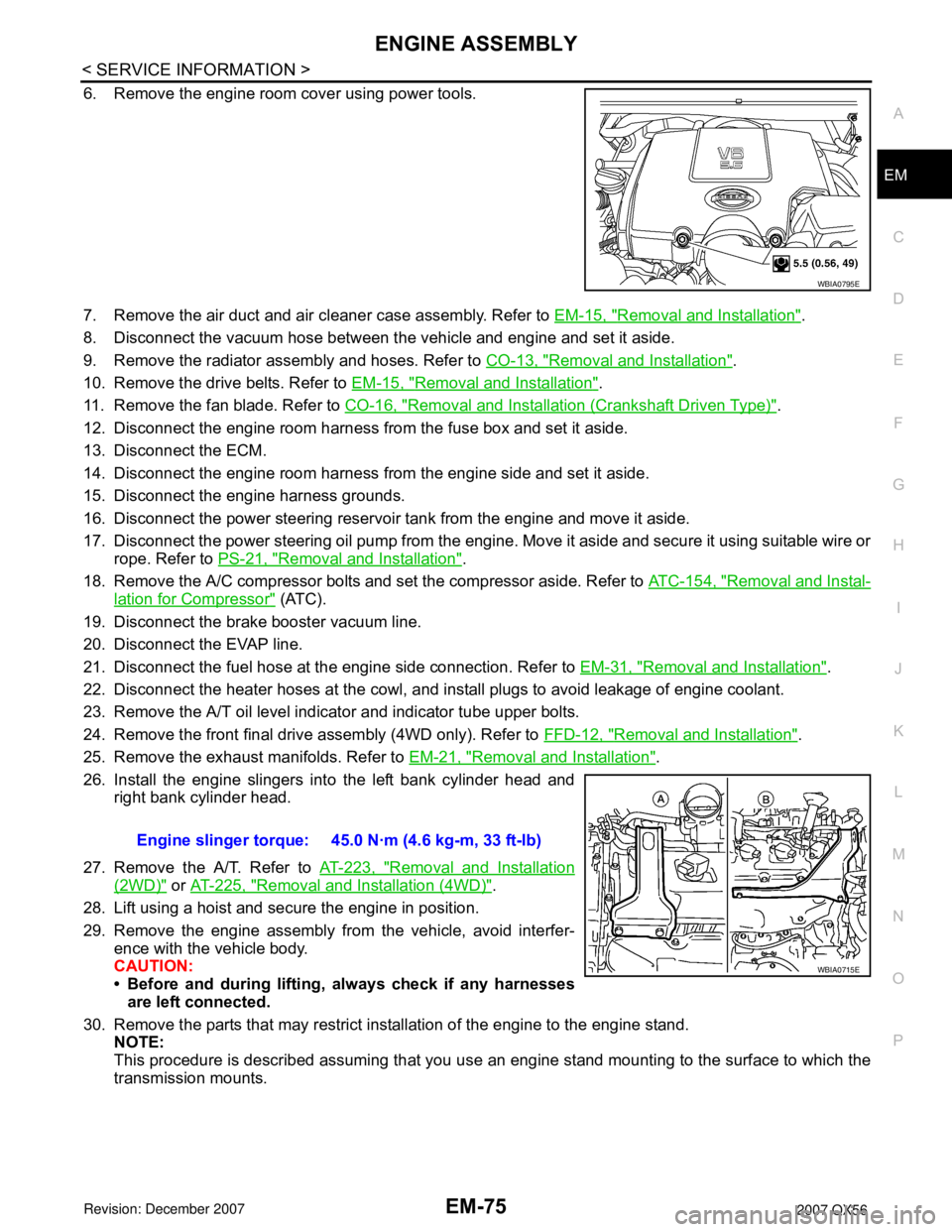
26. Install the engine slingers into the left bank cylinder head and
right bank cylinder head.
27. Remove the A/T. Refer to AT-223, "
Removal and Installation
(2WD)" or AT-225, "Removal and Installation (4WD)".
28. Lift using a hoist and secure the engine in position.
29. Remove the engine assembly from the vehicle, avoid interfer-
ence with the vehicle body.
CAUTION:
• Before and during lifting, always check if any harnesses
are left connected.
30. Remove the parts that may restrict installation of the engine to the engine stand.
NOTE:
This procedure is described assuming that you use an engine stand mounting to the surface to which the
transmission mounts.
WBIA0795E
Engine slinger torque: 45.0 N·m (4.6 kg-m, 33 ft-lb)
WBIA0715E
Page 1847 of 3061
ENGINE ASSEMBLY
EM-77
< SERVICE INFORMATION >
C
D
E
F
G
H
I
J
K
L
MA
EM
N
P O
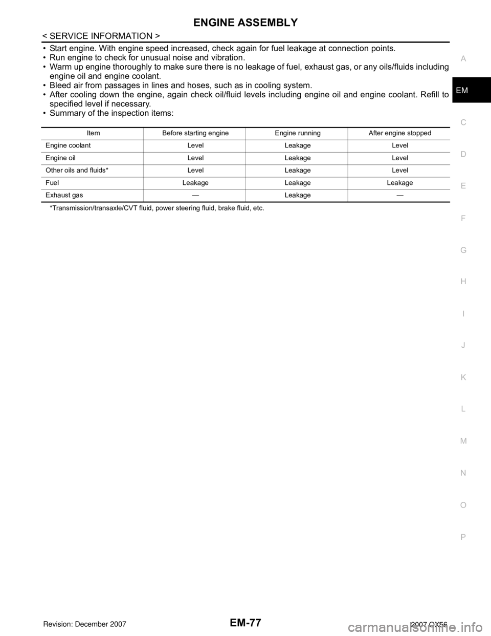
• Start engine. With engine speed increased, check again for fuel leakage at connection points.
• Run engine to check for unusual noise and vibration.
• Warm up engine thoroughly to make sure there is no leakage of fuel, exhaust gas, or any oils/fluids including
engine oil and engine coolant.
• Bleed air from passages in lines and hoses, such as in cooling system.
• After cooling down the engine, again check oil/fluid levels including engine oil and engine coolant. Refill to
specified level if necessary.
• Summary of the inspection items:
*Transmission/transaxle/CVT fluid, power steering fluid, brake fluid, etc.Item Before starting engine Engine running After engine stopped
Engine coolant Level Leakage Level
Engine oil Level Leakage Level
Other oils and fluids* Level Leakage Level
Fuel Leakage Leakage Leakage
Exhaust gas — Leakage —
Page 1889 of 3061
PREPARATION
FAX-3
< SERVICE INFORMATION >
C
E
F
G
H
I
J
K
L
MA
B
FA X
N
O
P
PREPARATION
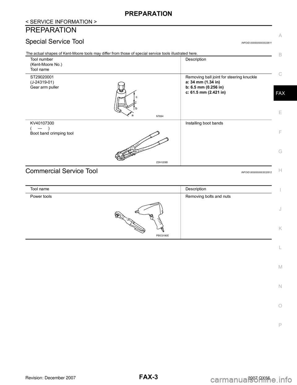
Special Service ToolINFOID:0000000003532611
The actual shapes of Kent-Moore tools may differ from those of special service tools illustrated here.
Commercial Service ToolINFOID:0000000003532612
Tool number
(Kent-Moore No.)
Tool nameDescription
ST29020001
(J-24319-01)
Gear arm pullerRemoving ball joint for steering knuckle
a: 34 mm (1.34 in)
b: 6.5 mm (0.256 in)
c: 61.5 mm (2.421 in)
KV40107300
(—)
Boot band crimping toolInstalling boot bands
NT694
ZZA1229D
Tool nameDescription
Power toolsRemoving bolts and nuts
PBIC0190E
Page 1891 of 3061

WHEEL HUB
FAX-5
< SERVICE INFORMATION >
C
E
F
G
H
I
J
K
L
MA
B
FA X
N
O
P
WHEEL HUB
On-Vehicle Inspection and ServiceINFOID:0000000003532614
Make sure the mounting conditions (looseness, backlash) of each component and component status (wear,
damage) are normal.
WHEEL BEARING INSPECTION
• Move wheel hub in the axial direction by hand. Make sure there is
no looseness of wheel bearing.
• Rotate wheel hub and make sure there is no unusual noise or
other irregular conditions. If there are any irregular conditions,
replace wheel hub and bearing assembly.
Removal and InstallationINFOID:0000000003532615
REMOVAL
1. Remove wheel and tire using power tool.
2. Remove engine under cover using power tool.
3. Without disassembling the hydraulic lines, remove caliper torque member bolts using power tool. Then
reposition brake caliper aside with wire. Refer to BR-19, "
Removal and Installation of Brake Caliper and
Disc Rotor" .
NOTE:
Do not press brake pedal while brake caliper is removed.Axial end play limit : 0.05 mm (0.002 in) or less
SMA571A
1. Disc rotor 2. Wheel hub and bearing assembly 3. Wheel stud
4. Splash guard 5. Steering knuckle
WDIA0043E
Page 1892 of 3061
FAX-6
< SERVICE INFORMATION >
WHEEL HUB
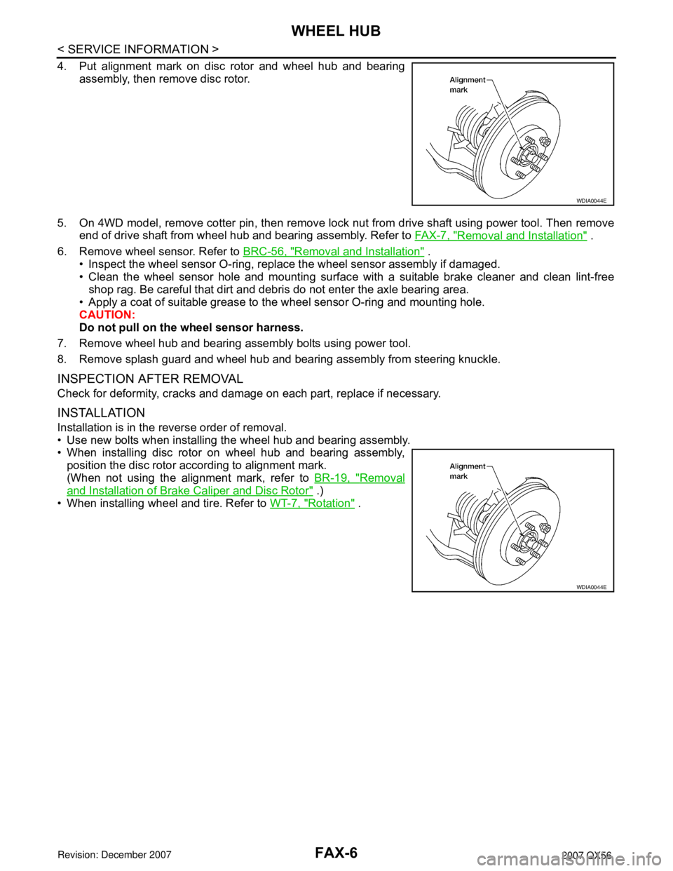
4. Put alignment mark on disc rotor and wheel hub and bearing
assembly, then remove disc rotor.
5. On 4WD model, remove cotter pin, then remove lock nut from drive shaft using power tool. Then remove
end of drive shaft from wheel hub and bearing assembly. Refer to FA X - 7 , "
Removal and Installation" .
6. Remove wheel sensor. Refer to BRC-56, "
Removal and Installation" .
• Inspect the wheel sensor O-ring, replace the wheel sensor assembly if damaged.
• Clean the wheel sensor hole and mounting surface with a suitable brake cleaner and clean lint-free
shop rag. Be careful that dirt and debris do not enter the axle bearing area.
• Apply a coat of suitable grease to the wheel sensor O-ring and mounting hole.
CAUTION:
Do not pull on the wheel sensor harness.
7. Remove wheel hub and bearing assembly bolts using power tool.
8. Remove splash guard and wheel hub and bearing assembly from steering knuckle.
INSPECTION AFTER REMOVAL
Check for deformity, cracks and damage on each part, replace if necessary.
INSTALLATION
Installation is in the reverse order of removal.
• Use new bolts when installing the wheel hub and bearing assembly.
• When installing disc rotor on wheel hub and bearing assembly,
position the disc rotor according to alignment mark.
(When not using the alignment mark, refer to BR-19, "
Removal
and Installation of Brake Caliper and Disc Rotor" .)
• When installing wheel and tire. Refer to WT-7, "
Rotation" .
WDIA0044E
WDIA0044E