2007 INFINITI QX56 power steering
[x] Cancel search: power steeringPage 2034 of 3061
POWER WINDOW SYSTEM
GW-15
< SERVICE INFORMATION >
C
D
E
F
G
H
J
K
L
MA
B
GW
N
O
P
POWER WINDOW SYSTEM
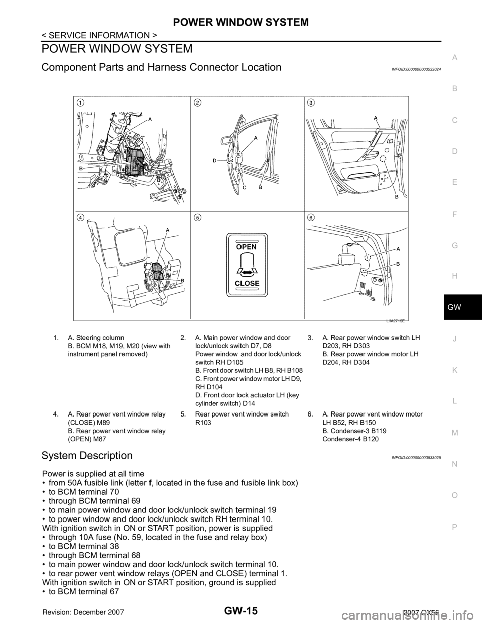
Component Parts and Harness Connector LocationINFOID:0000000003533024
System DescriptionINFOID:0000000003533025
Power is supplied at all time
• from 50A fusible link (letter f, located in the fuse and fusible link box)
• to BCM terminal 70
• through BCM terminal 69
• to main power window and door lock/unlock switch terminal 19
• to power window and door lock/unlock switch RH terminal 10.
With ignition switch in ON or START position, power is supplied
• through 10A fuse (No. 59, located in the fuse and relay box)
• to BCM terminal 38
• through BCM terminal 68
• to main power window and door lock/unlock switch terminal 10.
• to rear power vent window relays (OPEN and CLOSE) terminal 1.
With ignition switch in ON or START position, ground is supplied
• to BCM terminal 67
1. A. Steering column
B. BCM M18, M19, M20 (view with
instrument panel removed)2. A. Main power window and door
lock/unlock switch D7, D8
Power window and door lock/unlock
switch RH D105
B. Front door switch LH B8, RH B108
C. Front power window motor LH D9,
RH D104
D. Front door lock actuator LH (key
cylinder switch) D143. A. Rear power window switch LH
D203, RH D303
B. Rear power window motor LH
D204, RH D304
4. A. Rear power vent window relay
(CLOSE) M89
B. Rear power vent window relay
(OPEN) M875. Rear power vent window switch
R1036. A. Rear power vent window motor
LH B52, RH B150
B. Condenser-3 B119
Condenser-4 B120
LIIA2715E
Page 2087 of 3061
GW-68
< SERVICE INFORMATION >
REAR WINDOW DEFOGGER
REAR WINDOW DEFOGGER
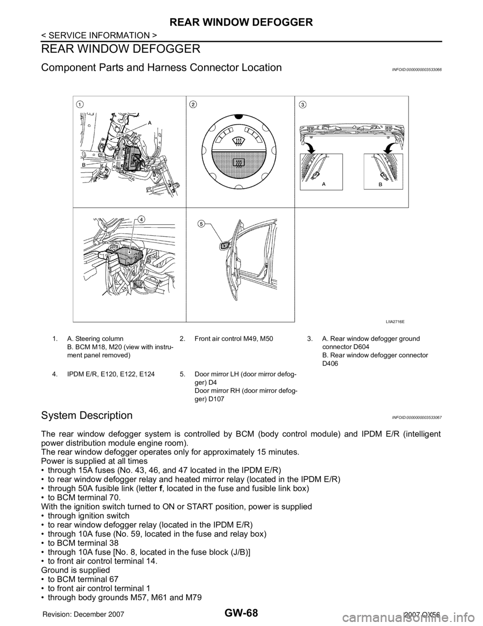
Component Parts and Harness Connector LocationINFOID:0000000003533066
System DescriptionINFOID:0000000003533067
The rear window defogger system is controlled by BCM (body control module) and IPDM E/R (intelligent
power distribution module engine room).
The rear window defogger operates only for approximately 15 minutes.
Power is supplied at all times
• through 15A fuses (No. 43, 46, and 47 located in the IPDM E/R)
• to rear window defogger relay and heated mirror relay (located in the IPDM E/R)
• through 50A fusible link (letter f, located in the fuse and fusible link box)
• to BCM terminal 70.
With the ignition switch turned to ON or START position, power is supplied
• through ignition switch
• to rear window defogger relay (located in the IPDM E/R)
• through 10A fuse (No. 59, located in the fuse and relay box)
• to BCM terminal 38
• through 10A fuse [No. 8, located in the fuse block (J/B)]
• to front air control terminal 14.
Ground is supplied
• to BCM terminal 67
• to front air control terminal 1
• through body grounds M57, M61 and M79
1. A. Steering column
B. BCM M18, M20 (view with instru-
ment panel removed)2. Front air control M49, M50 3. A. Rear window defogger ground
connector D604
B. Rear window defogger connector
D406
4. IPDM E/R, E120, E122, E124 5. Door mirror LH (door mirror defog-
ger) D4
Door mirror RH (door mirror defog-
ger) D107
LIIA2716E
Page 2110 of 3061
IDX-6
ALPHABETICAL INDEX
Line pressure solenoid valve ........................... AT-118
Line pressure switch (Transfer) .......... TF-154, TF-167
Line pressure test (A/T) ..................................... AT-52
Location of electrical units ................................. PG-65
Low coast brake solenoid valve ......... AT-151, AT-153
Low tire pressure warning system ...................... WT-8
Low tire pressure warning system - trouble diagnoses .
WT-11
Low tire pressure warning system - Wiring diagram .....
WT-11
Lubricant (R134a) A/C ..................................... ATC-22
Lubricants ......................................................... MA-11
Lubrication circuit (engine) ................................... LU-6
Lubrication oil A/C ............................................ ATC-22
Lubrication-locks, hinges and hood latches ...... MA-31
M
MAFS - Wiring diagram ..................... EC-200
, EC-208
Magnet clutch ............................... ATC-115, ATC-180
MAIN - Wiring diagram ...................... EC-150, AT-163
Main oil pump (Transfer) ..................... TF-154, TF-167
Mainshaft (Transfer) ........................... TF-154, TF-167
Maintenance (engine)Schedule 1 ....................... MA-7
Maintenance (engine)Schedule 2 ....................... MA-9
Major overhaul (Final drive) ............................. FFD-14
Major overhaul (Transfer) ................................ TF-146
Malfunction indicator lamp (MIL) ........................ EC-65
Map lamp .......................................................... LT-111
Mass air flow sensor (MAFS) ............. EC-197, EC-206
Meter ..................................................................... DI-5
METER - Wiring diagram ...................................... DI-9
MIL data link connectors circuit ....................... EC-697
MIL/DL - Wiring diagram .................................. EC-697
MIRROR - Wiring diagram ................................ GW-87
Misfire .............................................................. EC-350
Mode door control linkage adjustment ............. ATC-65
Mode door motor ............................ ATC-62, ATC-165
Model variation ................................................... GI-48
Multiport fuel injection (MFI) system .................. EC-25
Multiport fuel injection precautions ....................... GI-6
Multi-remote control system - See Remote keyless entry
system ............................................................... BL-40
N
NATS - Wiring diagram .................................... BL-130
NAVI - Wiring diagram ....................................... AV-86
NAVI Control Unit .............................................. AV-83
Navigation system ............................................. AV-81
Neutral-4LO switch ............................................ TF-61
NONDTC - Wiring diagram .............................. AT-172
NVH troubleshooting (AX) ................................. FAX-4
NVH troubleshooting (EM) ................................ EM-10
NVH troubleshooting (Final drive) ..................... RFD-7
NVH troubleshooting (Propeller shaft) ................. PR-3
NVH troubleshooting (RAX) .............................. RAX-4
NVH troubleshooting (RSU) .............................. RSU-5
NVH troubleshooting (ST) .................................... PS-5
NVH troubleshooting (Transfer) ......................... TF-10
NVH troubleshooting (WT)NVH troubleshooting (WT) ..
WT-4
NVIS (Nissan vehicle immobilizer system) precautions
GI-3
O
O2H2B1 - Wiring diagram ............................... EC-183
O2H2B2 - Wiring diagram ............................... EC-185
O2S2B1 - Wiring diagram ... EC-279, EC-290, EC-303
O2S2B2 - Wiring diagram ... EC-281, EC-292, EC-305
Oil cooler (engine) .............................................. LU-12
Oil filter ............................................................... LU-11
Oil filter (Transfer) ............................................ TF-143
Oil pan (engine) ................................................ EM-24
Oil pressure (engine) ........................................... LU-8
Oil pressure relief valve (engine) ......................... LU-6
Oil pump (engine) .............................................. LU-14
Oil seal replacement (engine) ........................... EM-60
Oil seal replacement (front of final drive) FFD-8, RFD-9
Oil seal replacement (side of final drive) ......... RFD-11
On board diagnostic system ............................. EC-49
ORVR (On-board Refueling Vapor Recovery) .. EC-40
Overheat ......................................................... EC-504
P
P/SCKT - Wiring diagram ................................. WW-46
Pantograph jack .................................................. GI-42
Park/Neutral position switch ............................ EC-487
Parking brake control ........................................... PB-4
PCV (positive crankcase ventilation) ................ EC-46
Periodic maintenance ......................................... MA-7
Personal lamp .................................................. LT-111
PGC/V - Wiring diagram ................... EC-397, EC-405
PHASE - Wiring diagram ................................ EC-371
PHONE - Wiring diagram ................................... AV-65
Pinion bearing preload diff. ............................. RFD-26
Piston pin inspection ......................................... EM-94
Piston ring inspection ........................................ EM-95
Piston to bore clearance ................................... EM-99
Planetary carrier (Transfer) ................. TF-149, TF-176
PNP/SW - Wiring diagram ... EC-489, AT-101, AT-102
POS - Wiring diagram ..................................... EC-364
POWER - Wiring diagram ................................... PG-6
Power door lock ................................................. BL-16
Power seat ......................................................... SE-81
Power steering fluid level .................................. MA-29
Power steering gear ........................................... PS-15
Power steering oil pump .................................... PS-22
Power steering pressure (PSP) sensor ........... EC-470
Power steering system bleeding .......................... PS-6
Power supply routing .......................................... PG-4
Power window .................................................. GW-15
PRE/SE - Wiring diagram ................. EC-429, EC-435
Precautions (General) ........................................... GI-4
Precautions in repairing high strength steel ..... BL-182
Pressure switch 1 ............................... AT-141, AT-155
Page 2123 of 3061
INSTRUMENT PANEL ASSEMBLY
IP-11
< SERVICE INFORMATION >
C
D
E
F
G
H
J
K
L
MA
B
IP
N
O
P Removal
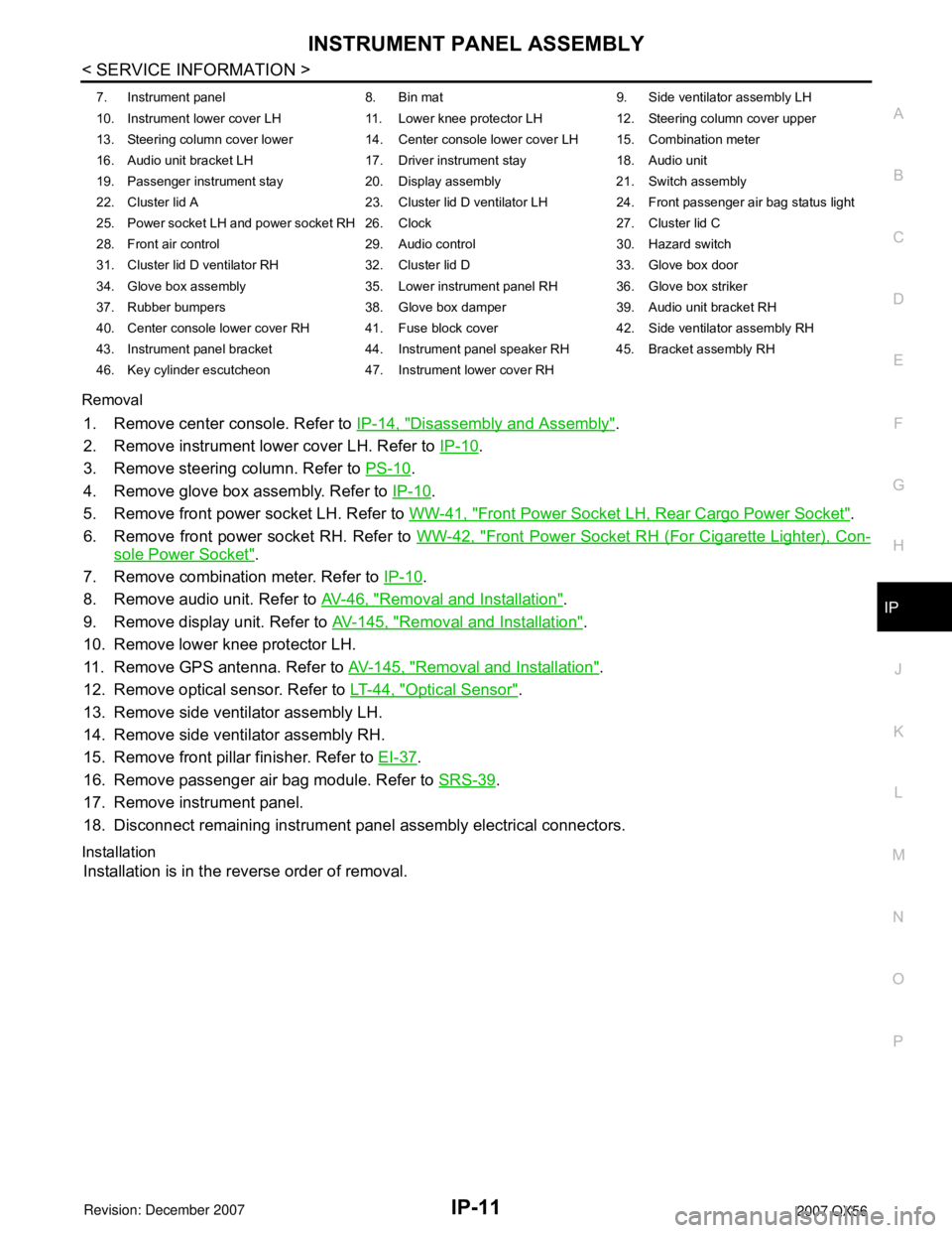
1. Remove center console. Refer to IP-14, "Disassembly and Assembly".
2. Remove instrument lower cover LH. Refer to IP-10
.
3. Remove steering column. Refer to PS-10
.
4. Remove glove box assembly. Refer to IP-10
.
5. Remove front power socket LH. Refer to WW-41, "
Front Power Socket LH, Rear Cargo Power Socket".
6. Remove front power socket RH. Refer to WW-42, "
Front Power Socket RH (For Cigarette Lighter), Con-
sole Power Socket".
7. Remove combination meter. Refer to IP-10
.
8. Remove audio unit. Refer to AV-46, "
Removal and Installation".
9. Remove display unit. Refer to AV-145, "
Removal and Installation".
10. Remove lower knee protector LH.
11. Remove GPS antenna. Refer to AV-145, "
Removal and Installation".
12. Remove optical sensor. Refer to LT-44, "
Optical Sensor".
13. Remove side ventilator assembly LH.
14. Remove side ventilator assembly RH.
15. Remove front pillar finisher. Refer to EI-37
.
16. Remove passenger air bag module. Refer to SRS-39
.
17. Remove instrument panel.
18. Disconnect remaining instrument panel assembly electrical connectors.
Installation
Installation is in the reverse order of removal.
7. Instrument panel 8. Bin mat 9. Side ventilator assembly LH
10. Instrument lower cover LH 11. Lower knee protector LH 12. Steering column cover upper
13. Steering column cover lower 14. Center console lower cover LH 15. Combination meter
16. Audio unit bracket LH 17. Driver instrument stay 18. Audio unit
19. Passenger instrument stay 20. Display assembly 21. Switch assembly
22. Cluster lid A 23. Cluster lid D ventilator LH 24. Front passenger air bag status light
25. Power socket LH and power socket RH 26. Clock 27. Cluster lid C
28. Front air control 29. Audio control 30. Hazard switch
31. Cluster lid D ventilator RH 32. Cluster lid D 33. Glove box door
34. Glove box assembly 35. Lower instrument panel RH 36. Glove box striker
37. Rubber bumpers 38. Glove box damper 39. Audio unit bracket RH
40. Center console lower cover RH 41. Fuse block cover 42. Side ventilator assembly RH
43. Instrument panel bracket 44. Instrument panel speaker RH 45. Bracket assembly RH
46. Key cylinder escutcheon 47. Instrument lower cover RH
Page 2125 of 3061
INSTRUMENT PANEL ASSEMBLY
IP-13
< SERVICE INFORMATION >
C
D
E
F
G
H
J
K
L
MA
B
IP
N
O
P
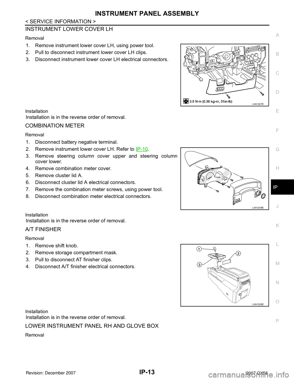
INSTRUMENT LOWER COVER LH
Removal
1. Remove instrument lower cover LH, using power tool.
2. Pull to disconnect instrument lower cover LH clips.
3. Disconnect instrument lower cover LH electrical connectors.
Installation
Installation is in the reverse order of removal.
COMBINATION METER
Removal
1. Disconnect battery negative terminal.
2. Remove instrument lower cover LH. Refer to IP-10
.
3. Remove steering column cover upper and steering column
cover lower.
4. Remove combination meter cover.
5. Remove cluster lid A.
6. Disconnect cluster lid A electrical connectors.
7. Remove the combination meter screws, using power tool.
8. Disconnect combination meter electrical connectors.
Installation
Installation is in the reverse order of removal.
A/T FINISHER
Removal
1. Remove shift knob.
2. Remove storage compartment mask.
3. Pull to disconnect AT finisher clips.
4. Disconnect A/T finisher electrical connectors.
Installation
Installation is in the reverse order of removal.
LOWER INSTRUMENT PANEL RH AND GLOVE BOX
Removal
LIIA1327E
LIIA1249E
LIIA1335E
Page 2203 of 3061
![INFINITI QX56 2007 Factory Service Manual LAN-72
< SERVICE INFORMATION >[CAN]
TROUBLE DIAGNOSIS
2.CHECK HARNESS FOR OPEN CIRCUIT
1. Disconnect the connector of front air control.
2. Check the resistance between the front air control harness c INFINITI QX56 2007 Factory Service Manual LAN-72
< SERVICE INFORMATION >[CAN]
TROUBLE DIAGNOSIS
2.CHECK HARNESS FOR OPEN CIRCUIT
1. Disconnect the connector of front air control.
2. Check the resistance between the front air control harness c](/manual-img/42/57029/w960_57029-2202.png)
LAN-72
< SERVICE INFORMATION >[CAN]
TROUBLE DIAGNOSIS
2.CHECK HARNESS FOR OPEN CIRCUIT
1. Disconnect the connector of front air control.
2. Check the resistance between the front air control harness connector terminals.
OK or NG
OK >> GO TO 3.
NG >> Repair the front air control branch line.
3.CHECK POWER SUPPLY AND GROUND CIRCUIT
Check the power supply and the ground circuit of the front air control. Refer to ATC-36, "
Schematic".
OK or NG
OK >> • Present error: Replace the front air control. Refer to ATC-123, "Removal and Installation".
• Past error: Error was detected in the front air control branch line.
NG >> Repair the power supply and the ground circuit.
Combination Meter Branch Line CircuitINFOID:0000000003533655
INSPECTION PROCEDURE
1.CHECK CONNECTOR
1. Turn the ignition switch OFF.
2. Disconnect the battery cable from the negative terminal.
3. Check the terminals and connectors of the combination meter for damage, bend and loose connection
(unit side and connector side).
OK or NG
OK >> GO TO 2.
NG >> Repair the terminal and connector.
2.CHECK HARNESS FOR OPEN CIRCUIT
1. Disconnect the connector of combination meter.
2. Check the resistance between the combination meter harness connector terminals.
OK or NG
OK >> GO TO 3.
NG >> Repair the combination meter branch line.
3.CHECK POWER SUPPLY AND GROUND CIRCUIT
Check the power supply and the ground circuit of the combination meter. Refer to DI-9, "
Wiring Diagram -
METER -".
OK or NG
OK >> • Present error: Replace the combination meter. Refer to IP-10, "Removal and Installation".
• Past error: Error was detected in the combination meter branch line.
NG >> Repair the power supply and the ground circuit.
Steering Angle Sensor Branch Line CircuitINFOID:0000000003533656
INSPECTION PROCEDURE
1.CHECK CONNECTOR
1. Turn the ignition switch OFF.
Front air control harness connector
Resistance (Ω)
Connector No. Terminal No.
M50 34 35 Approx. 54 – 66
Combination meter harness connector
Resistance (Ω)
Connector No. Terminal No.
M24 11 12 Approx. 54 – 66
Page 2204 of 3061
![INFINITI QX56 2007 Factory Service Manual TROUBLE DIAGNOSIS
LAN-73
< SERVICE INFORMATION >[CAN]
C
D
E
F
G
H
I
J
L
MA
B
LAN
N
O
P
2. Disconnect the battery cable from the negative terminal.
3. Check the terminals and connectors of the steering INFINITI QX56 2007 Factory Service Manual TROUBLE DIAGNOSIS
LAN-73
< SERVICE INFORMATION >[CAN]
C
D
E
F
G
H
I
J
L
MA
B
LAN
N
O
P
2. Disconnect the battery cable from the negative terminal.
3. Check the terminals and connectors of the steering](/manual-img/42/57029/w960_57029-2203.png)
TROUBLE DIAGNOSIS
LAN-73
< SERVICE INFORMATION >[CAN]
C
D
E
F
G
H
I
J
L
MA
B
LAN
N
O
P
2. Disconnect the battery cable from the negative terminal.
3. Check the terminals and connectors of the steering angle sensor for damage, bend and loose connection
(unit side and connector side).
OK or NG
OK >> GO TO 2.
NG >> Repair the terminal and connector.
2.CHECK HARNESS FOR OPEN CIRCUIT
1. Disconnect the connector of steering angle sensor.
2. Check the resistance between the steering angle sensor harness connector terminals.
OK or NG
OK >> GO TO 3.
NG >> Repair the steering angle sensor branch line.
3.CHECK POWER SUPPLY AND GROUND CIRCUIT
Check the power supply and the ground circuit of the steering angle sensor. Refer to BRC-15, "
Schematic".
OK or NG
OK >> • Present error: Replace the steering angle sensor. Refer to BRC-60, "Removal and Installation".
• Past error: Error was detected in the steering angle sensor branch line.
NG >> Repair the power supply and the ground circuit.
Transfer Control Unit Branch Line CircuitINFOID:0000000003533657
INSPECTION PROCEDURE
1.CHECK CONNECTOR
1. Turn the ignition switch OFF.
2. Disconnect the battery cable from the negative terminal.
3. Check the terminals and connectors of the transfer control unit for damage, bend and loose connection
(unit side and connector side).
OK or NG
OK >> GO TO 2.
NG >> Repair the terminal and connector.
2.CHECK HARNESS FOR OPEN CIRCUIT
1. Disconnect the connector of transfer control unit.
2. Check the resistance between the transfer control unit harness connector terminals.
OK or NG
OK >> GO TO 3.
NG >> Repair the transfer control unit branch line.
3.CHECK POWER SUPPLY AND GROUND CIRCUIT
Check the power supply and the ground circuit of the transfer control unit. Refer to TF-23, "
Circuit Diagram".
OK or NG
OK >> • Present error: Replace the transfer control unit. Refer to TF-115, "Removal and Installation".
• Past error: Error was detected in the transfer control unit branch line.
NG >> Repair the power supply and the ground circuit.
Steering angle sensor harness connector
Resistance (Ω)
Connector No. Terminal No.
M47 3 4 Approx. 54 – 66
Transfer control unit harness connector
Resistance (Ω)
Connector No. Terminal No.
E142 7 8 Approx. 54 – 66
Page 2301 of 3061
LT-94
< SERVICE INFORMATION >
TRAILER TOW
TRAILER TOW
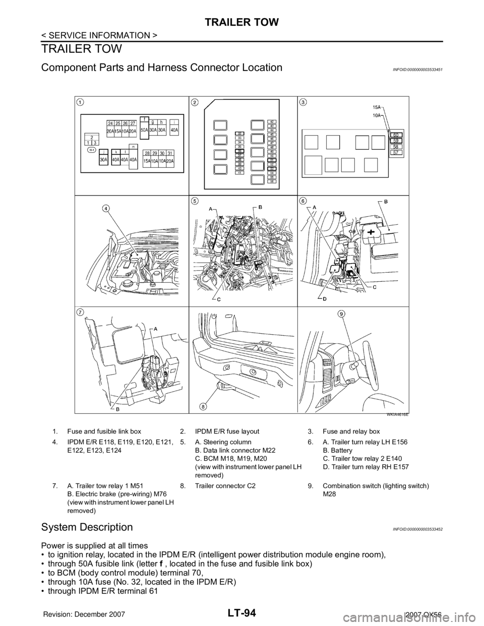
Component Parts and Harness Connector LocationINFOID:0000000003533451
System DescriptionINFOID:0000000003533452
Power is supplied at all times
• to ignition relay, located in the IPDM E/R (intelligent power distribution module engine room),
• through 50A fusible link (letter f , located in the fuse and fusible link box)
• to BCM (body control module) terminal 70,
• through 10A fuse (No. 32, located in the IPDM E/R)
• through IPDM E/R terminal 61
1. Fuse and fusible link box 2. IPDM E/R fuse layout 3. Fuse and relay box
4. IPDM E/R E118, E119, E120, E121,
E122, E123, E1245. A. Steering column
B. Data link connector M22
C. BCM M18, M19, M20
(view with instrument lower panel LH
removed)6. A. Trailer turn relay LH E156
B. Battery
C. Trailer tow relay 2 E140
D. Trailer turn relay RH E157
7. A. Trailer tow relay 1 M51
B. Electric brake (pre-wiring) M76
(view with instrument lower panel LH
removed)8. Trailer connector C2 9. Combination switch (lighting switch)
M28
WKIA4616E