Page 1893 of 3061
DRIVE SHAFT
FAX-7
< SERVICE INFORMATION >
C
E
F
G
H
I
J
K
L
MA
B
FA X
N
O
P
DRIVE SHAFT
Removal and InstallationINFOID:0000000003532616
REMOVAL
1. Remove wheel and tire using power tool.
2. Remove engine under cover using power tool.
3. Remove wheel sensor harness from mount on knuckle.
CAUTION:
Do not pull on wheel sensor harness.
4. Without disassembling the hydraulic lines, remove brake caliper using power tool. Reposition it aside with
wire. Refer to BR-19, "
Removal and Installation of Brake Caliper and Disc Rotor" .
NOTE:
Avoid depressing brake pedal while brake caliper is removed.
5. Remove coil spring and shock absorber assembly using power tool. Refer to FSU-10, "
Removal and
Installation" .
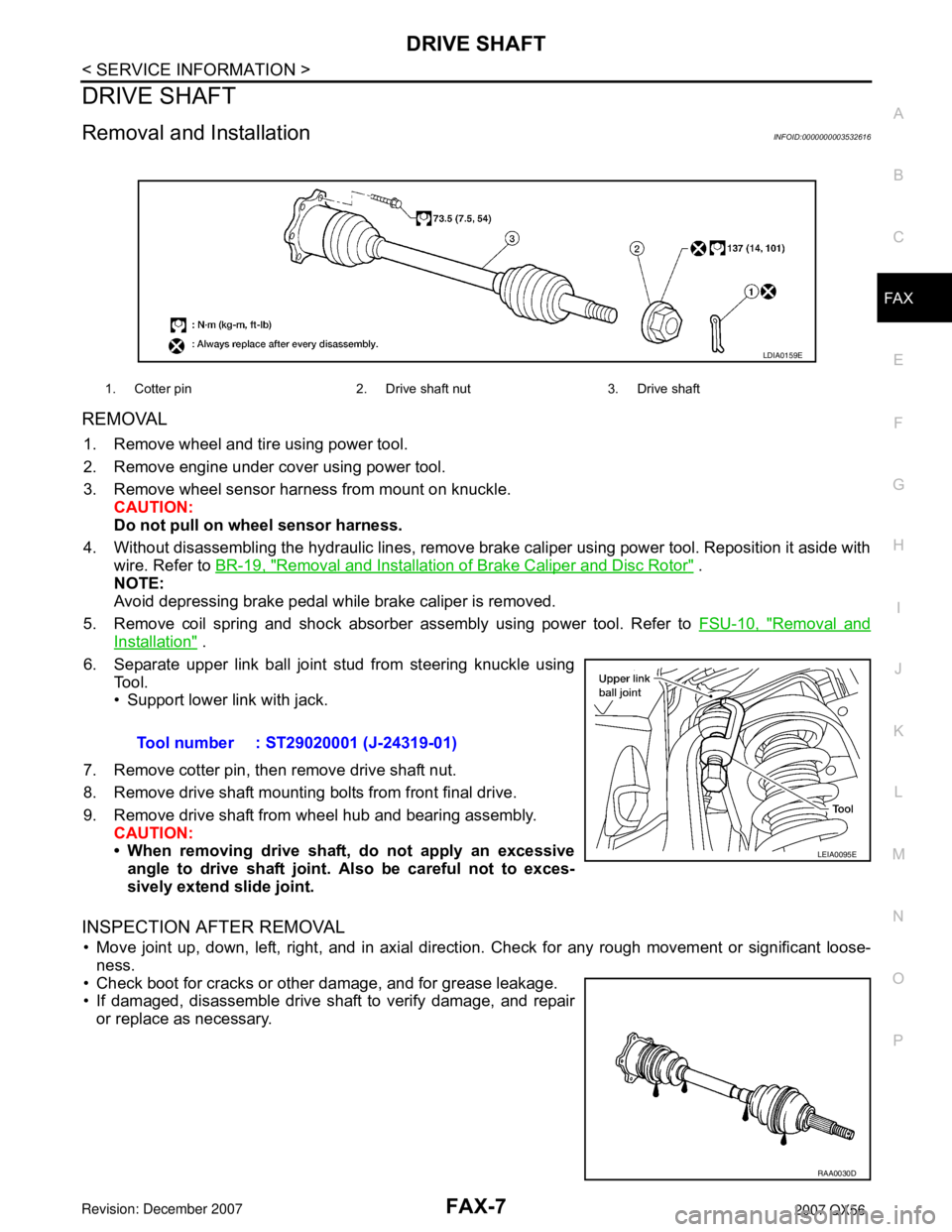
6. Separate upper link ball joint stud from steering knuckle using
Tool.
• Support lower link with jack.
7. Remove cotter pin, then remove drive shaft nut.
8. Remove drive shaft mounting bolts from front final drive.
9. Remove drive shaft from wheel hub and bearing assembly.
CAUTION:
• When removing drive shaft, do not apply an excessive
angle to drive shaft joint. Also be careful not to exces-
sively extend slide joint.
INSPECTION AFTER REMOVAL
• Move joint up, down, left, right, and in axial direction. Check for any rough movement or significant loose-
ness.
• Check boot for cracks or other damage, and for grease leakage.
• If damaged, disassemble drive shaft to verify damage, and repair
or replace as necessary.
1. Cotter pin 2. Drive shaft nut 3. Drive shaft
LDIA0159E
Tool number : ST29020001 (J-24319-01)
LEIA0095E
RAA0030D
Page 1956 of 3061
FSU-10
< SERVICE INFORMATION >
COIL SPRING AND SHOCK ABSORBER
COIL SPRING AND SHOCK ABSORBER
Removal and InstallationINFOID:0000000003532638
REMOVAL
1. Remove the wheel and tire using power tool.
2. Remove the shock absorber lower bolt using power tool.
3. Remove the three shock absorber upper nuts using power tool.
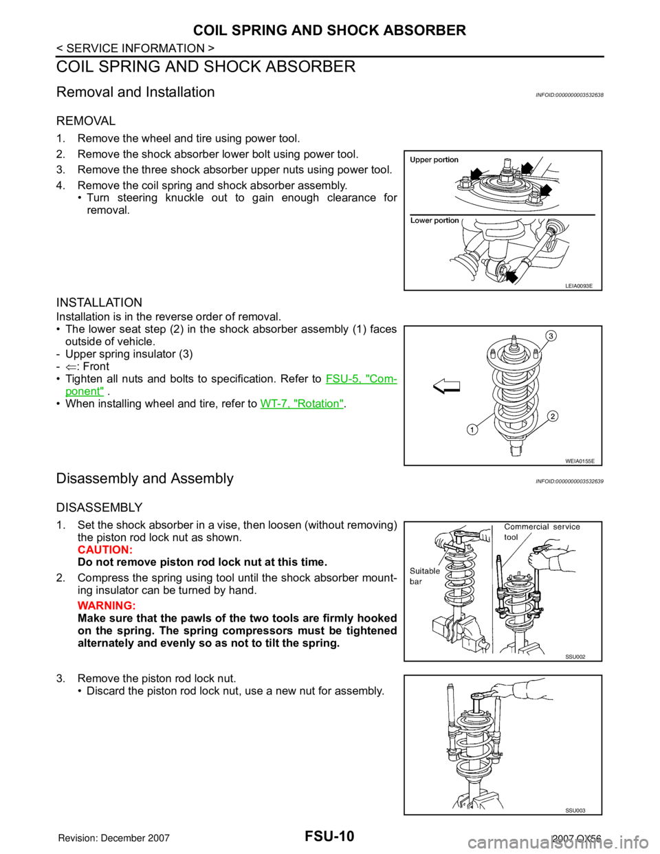
4. Remove the coil spring and shock absorber assembly.
• Turn steering knuckle out to gain enough clearance for
removal.
INSTALLATION
Installation is in the reverse order of removal.
• The lower seat step (2) in the shock absorber assembly (1) faces
outside of vehicle.
- Upper spring insulator (3)
-⇐: Front
• Tighten all nuts and bolts to specification. Refer to FSU-5, "
Com-
ponent" .
• When installing wheel and tire, refer to WT-7, "
Rotation".
Disassembly and AssemblyINFOID:0000000003532639
DISASSEMBLY
1. Set the shock absorber in a vise, then loosen (without removing)
the piston rod lock nut as shown.
CAUTION:
Do not remove piston rod lock nut at this time.
2. Compress the spring using tool until the shock absorber mount-
ing insulator can be turned by hand.
WARNING:
Make sure that the pawls of the two tools are firmly hooked
on the spring. The spring compressors must be tightened
alternately and evenly so as not to tilt the spring.
3. Remove the piston rod lock nut.
• Discard the piston rod lock nut, use a new nut for assembly.
LEIA0093E
WEIA0155E
SSU002
SSU003
Page 1959 of 3061
UPPER LINK
FSU-13
< SERVICE INFORMATION >
C
D
F
G
H
I
J
K
L
MA
B
FSU
N
O
P
UPPER LINK
Removal and InstallationINFOID:0000000003532641
REMOVAL
1. Remove the wheel and tire using power tool.
2. Remove the fender protector to access upper link. Refer to EI-22, "
Removal and Installation" .
3. Remove cotter pin and nut from upper link ball joint and discard the cotter pin.
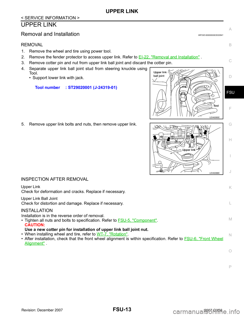
4. Separate upper link ball joint stud from steering knuckle using
Tool.
• Support lower link with jack.
5. Remove upper link bolts and nuts, then remove upper link.
INSPECTION AFTER REMOVAL
Upper Link
Check for deformation and cracks. Replace if necessary.
Upper Link Ball Joint
Check for distortion and damage. Replace if necessary.
INSTALLATION
Installation is in the reverse order of removal.
• Tighten all nuts and bolts to specification. Refer to FSU-5, "
Component".
CAUTION:
Use a new cotter pin for installation of upper link ball joint nut.
• When installing wheel and tire, refer to WT-7, "
Rotation".
• After installation, check that the front wheel alignment is within specification. Refer to FSU-6, "
Front Wheel
Alignment" . Tool number : ST29020001 (J-24319-01)
LEIA0095E
LEIA0096E
Page 1960 of 3061
FSU-14
< SERVICE INFORMATION >
LOWER LINK
LOWER LINK
Removal and InstallationINFOID:0000000003532642
REMOVAL
1. Remove the wheel and tire using power tool.
2. Remove lower shock absorber bolt.
3. Remove stabilizer bar connecting rod lower nut using power tool, then separate connecting rod from lower
link. Refer to FSU-12, "
Removal and Installation".
4. Remove drive shaft nut, if equipped. Refer to FA X - 7 , "
Removal and Installation".
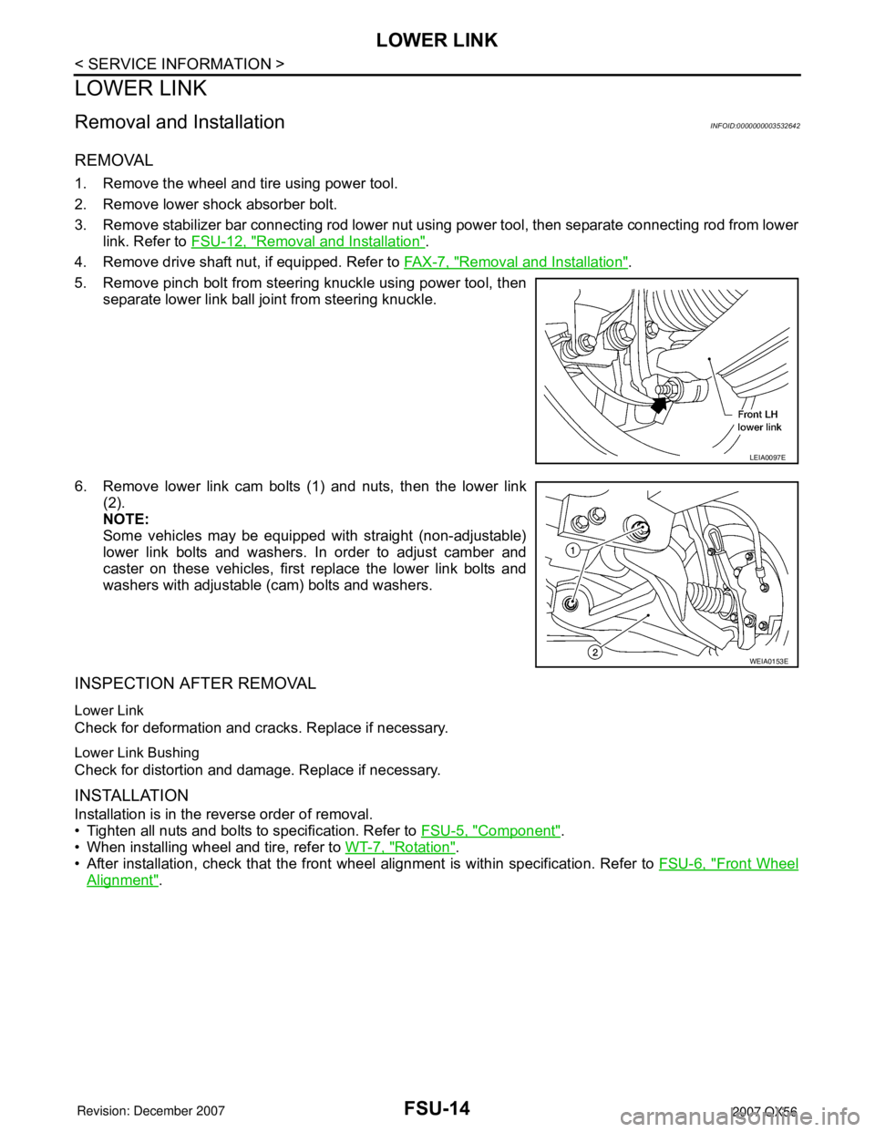
5. Remove pinch bolt from steering knuckle using power tool, then
separate lower link ball joint from steering knuckle.
6. Remove lower link cam bolts (1) and nuts, then the lower link
(2).
NOTE:
Some vehicles may be equipped with straight (non-adjustable)
lower link bolts and washers. In order to adjust camber and
caster on these vehicles, first replace the lower link bolts and
washers with adjustable (cam) bolts and washers.
INSPECTION AFTER REMOVAL
Lower Link
Check for deformation and cracks. Replace if necessary.
Lower Link Bushing
Check for distortion and damage. Replace if necessary.
INSTALLATION
Installation is in the reverse order of removal.
• Tighten all nuts and bolts to specification. Refer to FSU-5, "
Component".
• When installing wheel and tire, refer to WT-7, "
Rotation".
• After installation, check that the front wheel alignment is within specification. Refer to FSU-6, "
Front Wheel
Alignment".
LEIA0097E
WEIA0153E
Page 1963 of 3061
KNUCKLE
FSU-17
< SERVICE INFORMATION >
C
D
F
G
H
I
J
K
L
MA
B
FSU
N
O
P
KNUCKLE
On-Vehicle Inspection and ServiceINFOID:0000000003532645
Make sure the mounting conditions (looseness, backlash) of each component and component status (wear,
damage) are within specifications. Refer to FSU-20, "
Ball Joint" .
Removal and InstallationINFOID:0000000003532646
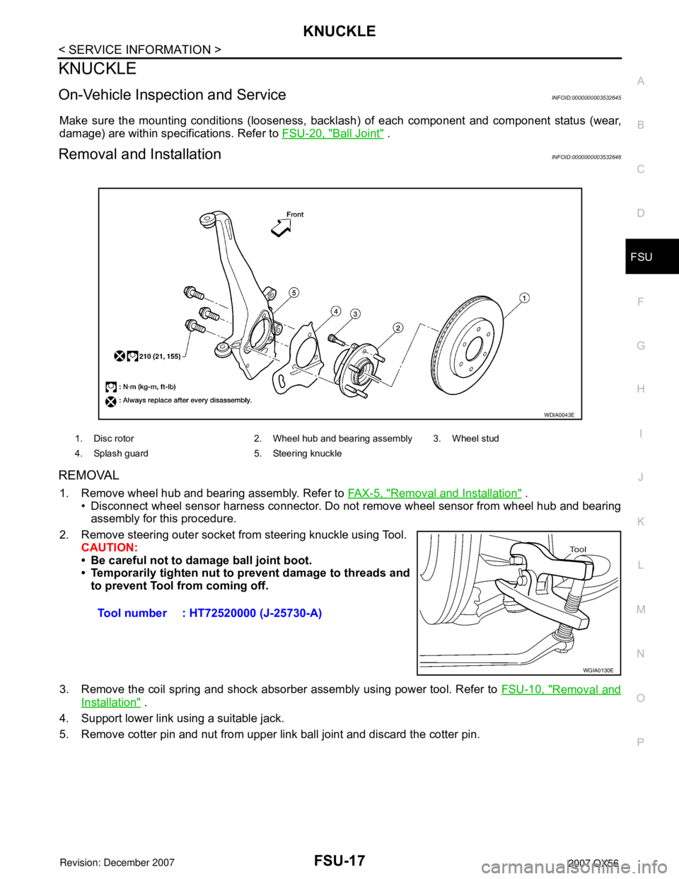
REMOVAL
1. Remove wheel hub and bearing assembly. Refer to FAX-5, "Removal and Installation" .
• Disconnect wheel sensor harness connector. Do not remove wheel sensor from wheel hub and bearing
assembly for this procedure.
2. Remove steering outer socket from steering knuckle using Tool.
CAUTION:
• Be careful not to damage ball joint boot.
• Temporarily tighten nut to prevent damage to threads and
to prevent Tool from coming off.
3. Remove the coil spring and shock absorber assembly using power tool. Refer to FSU-10, "
Removal and
Installation" .
4. Support lower link using a suitable jack.
5. Remove cotter pin and nut from upper link ball joint and discard the cotter pin.
1. Disc rotor 2. Wheel hub and bearing assembly 3. Wheel stud
4. Splash guard 5. Steering knuckle
WDIA0043E
Tool number : HT72520000 (J-25730-A)
WGIA0130E
Page 1964 of 3061
FSU-18
< SERVICE INFORMATION >
KNUCKLE
6. Separate upper link ball joint from steering knuckle using Tool.
7. Remove pinch bolt from steering knuckle using power tool, then
separate lower link ball joint from steering knuckle.
8. Remove steering knuckle from vehicle.
INSPECTION AFTER REMOVAL
Check for deformity, cracks and damage on each part, replace if necessary.
• Perform ball joint inspection. Refer to FSU-15, "
Inspection" .
INSTALLATION
Installation is in the reverse order of removal.
• Refer to FSU-5, "
Component" for tightening torques.
CAUTION:
Use a new cotter pin for installation of lock nut.
• When installing disc rotor on wheel hub and bearing assembly,
align the marks.
NOTE:
When not using the alignment mark, refer to BR-18
.
• When installing wheel and tire, refer to WT-7, "
Rotation" . Tool number : ST29020001 (J-24319-01)
LEIA0095E
LEIA0097E
WDIA0044E
Page 1987 of 3061
HOW TO USE THIS MANUAL
GI-21
< SERVICE INFORMATION >
C
D
E
F
G
H
I
J
K
L
MB
GI
N
O
PLH, RH Left-Hand, Right-Hand
M/T Manual Transaxle/Transmission
OD Overdrive
P/S Power Steering
SAE Society of Automotive Engineers, Inc.
SDS Service Data and Specifications
SST Special Service Tools
2WD 2-Wheel Drive
2
22nd range 2nd gear
2
12nd range 1st gear
1
21st range 2nd gear
1
11st range 1st gear ABBREVIATION DESCRIPTION
Page 2008 of 3061
GI-42
< SERVICE INFORMATION >
TOW TRUCK TOWING
TOW TRUCK TOWING
Tow Truck TowingINFOID:0000000003531499
WARNING:
• Never get under the vehicle while it is supported only by the jack. Always use safety stands to sup-
port the frame when you have to get under the vehicle.
• Place wheel chocks at both front and back of the wheels on the ground.
CAUTION:
• All applicable State or Provincial (in Canada) laws and local laws regarding the towing operation
must be obeyed.
• It is necessary to use proper towing equipment to avoid possible damage during towing operation.
Towing is in accordance with Towing Procedure Manual at dealer.
• Always attach safety chains before towing.
• When towing, make sure that the transmission, steering system and powertrain are in good order. If
any unit is damaged, dollies must be used.
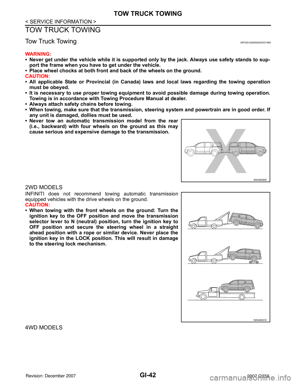
• Never tow an automatic transmission model from the rear
(i.e., backward) with four wheels on the ground as this may
cause serious and expensive damage to the transmission.
2WD MODELS
INFINITI does not recommend towing automatic transmission
equipped vehicles with the drive wheels on the ground.
CAUTION:
• When towing with the front wheels on the ground: Turn the
ignition key to the OFF position and move the transmission
selector lever to N (neutral) position, turn the ignition key to
OFF position and secure the steering wheel in a straight
ahead position with a rope or similar device. Never place the
ignition key in the LOCK position. This will result in damage
to the steering lock mechanism.
4WD MODELS
WAIA0030E
WAIA0031E