2007 INFINITI QX56 power steering
[x] Cancel search: power steeringPage 2683 of 3061
AUTOMATIC DRIVE POSITIONER
SE-11
< SERVICE INFORMATION >
C
D
E
F
G
H
J
K
L
MA
B
SE
N
O
P
AUTOMATIC DRIVE POSITIONER
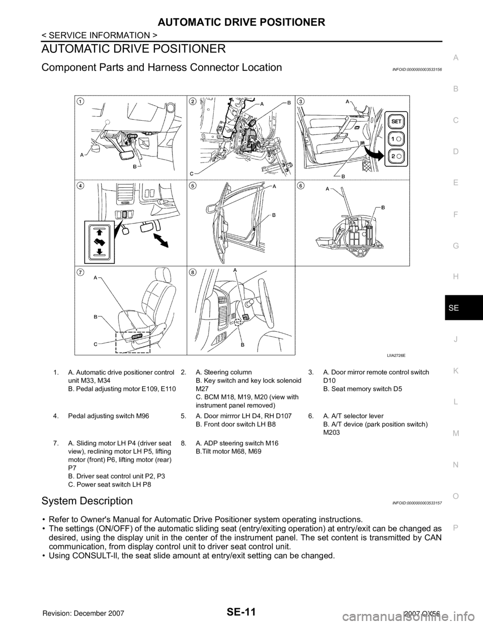
Component Parts and Harness Connector LocationINFOID:0000000003533156
System DescriptionINFOID:0000000003533157
• Refer to Owner's Manual for Automatic Drive Positioner system operating instructions.
• The settings (ON/OFF) of the automatic sliding seat (entry/exiting operation) at entry/exit can be changed as
desired, using the display unit in the center of the instrument panel. The set content is transmitted by CAN
communication, from display control unit to driver seat control unit.
• Using CONSULT-ll, the seat slide amount at entry/exit setting can be changed.
1. A. Automatic drive positioner control
unit M33, M34
B. Pedal adjusting motor E109, E1102. A. Steering column
B. Key switch and key lock solenoid
M27
C. BCM M18, M19, M20 (view with
instrument panel removed)3. A. Door mirror remote control switch
D10
B. Seat memory switch D5
4. Pedal adjusting switch M96 5. A. Door mirrror LH D4, RH D107
B. Front door switch LH B86. A. A/T selector lever
B. A/T device (park position switch)
M203
7. A. Sliding motor LH P4 (driver seat
view), reclining motor LH P5, lifting
motor (front) P6, lifting motor (rear)
P7
B. Driver seat control unit P2, P3
C. Power seat switch LH P88. A. ADP steering switch M16
B.Tilt motor M68, M69
LIIA2726E
Page 2684 of 3061

SE-12
< SERVICE INFORMATION >
AUTOMATIC DRIVE POSITIONER
NOTE:
• Disconnecting the battery erases the stored memory.
• After connecting the battery, insert the key into the ignition cylinder and turn the front door switch LH ON (open)→OFF (close)→ON
(open), the entry/exiting function becomes possible.
• After Exiting operation is carried out, return operation can be operated.
NOTE:
During automatic operation, if the ignition switch is turned ON→START, the automatic operation is suspended. When the ignition switch
returns to ON, it resumes.
FA I L - S A F E M O D E
When any manual and automatic operations are not performed, if any motor operations of seats or pedals are
detected for T2 or more, status is judged “Output error”.
CANCEL OF FAIL-SAFE MODE
The mode is cancelled when the A/T selector lever is shifted to P position from any other position.
NOTE:
The front seat LH position and pedal adjustment functions (see the following table) operate simultaneously in
the order of priority.
*: In conjunction with sliding the seat, the door mirrors are positioned.Function Description
Memory operation The front seat LH, steering wheel, pedals (accelerator, brake) and door mirrors move
to the stored driving position by pushing seat memory switch (1 or 2).
Entry/exit-
ing functionExiting operation At exit, the seat moves backward and the steering wheel raises. (Exiting position)
Entry operationAt entry, the seat and steering wheel return from exiting position to the previous driving
position before the exiting operation.
Keyfob interlock operationPerform memory operation, turnout operation and return operation by pressing keyfob
unlock button.
Auto operation temporary stop
conditions.When ignition switch is turned to START during seat memory switch operation and return
operation, seat memory switch operation and return operation is stopped.
Auto operation stop conditions.• When the vehicle speed becomes 7 km/h (4 MPH) or higher (memory switch operation
and entry operation).
• When the setting switch, seat memory switch 1, or 2 are pressed.
• When A/T selector lever is in any position other than P.
• When the door mirror remote control switch is operated (when ignition switch turned to
ON).
• When power seat switch turned ON.
• When pedal adjusting switch turned ON.
• When front seat sliding entry/exiting setting is OFF (entry/exiting operation).
OPERATED PORTION T2
Seat sliding Approx. 0.1 sec.
Seat reclining Same as above
Seat lifting (Front) Same as above
Seat lifting (Rear) Same as above
Steering wheel Same as above
Pedal adjust Same as above
Priority Function Priority Function
1 Seat sliding, (door mirror LH/RH)* 4 Seat reclining
2 Pedal 5 Seat lifter-FR
3 Steering wheel 6 Seat lifter-RR
Page 2701 of 3061
AUTOMATIC DRIVE POSITIONER
SE-29
< SERVICE INFORMATION >
C
D
E
F
G
H
J
K
L
MA
B
SE
N
O
P
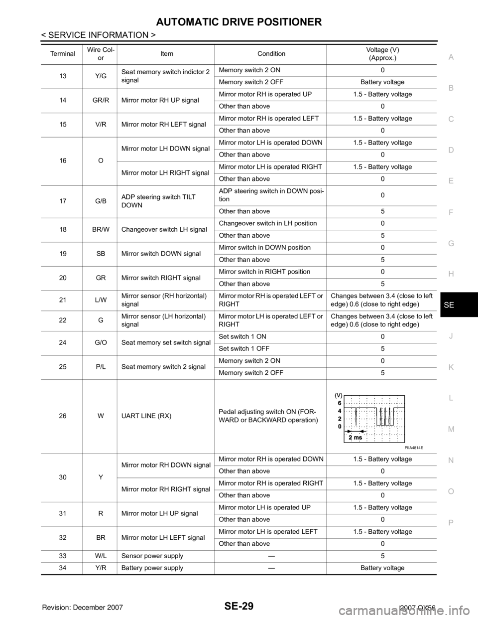
13 Y/GSeat memory switch indictor 2
signalMemory switch 2 ON 0
Memory switch 2 OFF Battery voltage
14 GR/R Mirror motor RH UP signalMirror motor RH is operated UP 1.5 - Battery voltage
Other than above 0
15 V/R Mirror motor RH LEFT signalMirror motor RH is operated LEFT 1.5 - Battery voltage
Other than above 0
16 OMirror motor LH DOWN signalMirror motor LH is operated DOWN 1.5 - Battery voltage
Other than above 0
Mirror motor LH RIGHT signalMirror motor LH is operated RIGHT 1.5 - Battery voltage
Other than above 0
17 G/BADP steering switch TILT
DOWNADP steering switch in DOWN posi-
tion0
Other than above 5
18 BR/W Changeover switch LH signalChangeover switch in LH position 0
Other than above 5
19 SB Mirror switch DOWN signalMirror switch in DOWN position 0
Other than above 5
20 GR Mirror switch RIGHT signalMirror switch in RIGHT position 0
Other than above 5
21 L/WMirror sensor (RH horizontal)
signalMirror motor RH is operated LEFT or
RIGHTChanges between 3.4 (close to left
edge) 0.6 (close to right edge)
22 GMirror sensor (LH horizontal)
signalMirror motor LH is operated LEFT or
RIGHTChanges between 3.4 (close to left
edge) 0.6 (close to right edge)
24 G/O Seat memory set switch signalSet switch 1 ON 0
Set switch 1 OFF 5
25 P/L Seat memory switch 2 signalMemory switch 2 ON 0
Memory switch 2 OFF 5
26 W UART LINE (RX)Pedal adjusting switch ON (FOR-
WARD or BACKWARD operation)
30 YMirror motor RH DOWN signalMirror motor RH is operated DOWN 1.5 - Battery voltage
Other than above 0
Mirror motor RH RIGHT signalMirror motor RH is operated RIGHT 1.5 - Battery voltage
Other than above 0
31 R Mirror motor LH UP signalMirror motor LH is operated UP 1.5 - Battery voltage
Other than above 0
32 BR Mirror motor LH LEFT signalMirror motor LH is operated LEFT 1.5 - Battery voltage
Other than above 0
33 W/L Sensor power supply — 5
34 Y/R Battery power supply — Battery voltage Te r m i n a l Wire Col-
orItem ConditionVoltage (V)
(Approx.)
PIIA4814E
Page 2702 of 3061
SE-30
< SERVICE INFORMATION >
AUTOMATIC DRIVE POSITIONER
Work Flow
INFOID:0000000003533166
1. Check the symptom and customer's requests.
2. Understand the system description. Refer to SE-11, "
System Description".
3. Perform the preliminary check. Refer to SE-30, "
Preliminary Check" .
4. Check the self-diagnosis, results using CONSULT-II. Refer to SE-32, "
CONSULT-II Function (AUTO
DRIVE POS.)".
5. Repair or replace depending on the self-diagnostic results.
6. Based on the trouble diagnosis chart, repair or replace the cause of the malfunction. Refer to SE-35,
"Symptom Chart" .
7. Does the automatic drive positioner system operate normally?
If it is normal, GO TO 8.
If it is not normal, GO TO 3.
8. Inspection End.
Preliminary CheckINFOID:0000000003533167
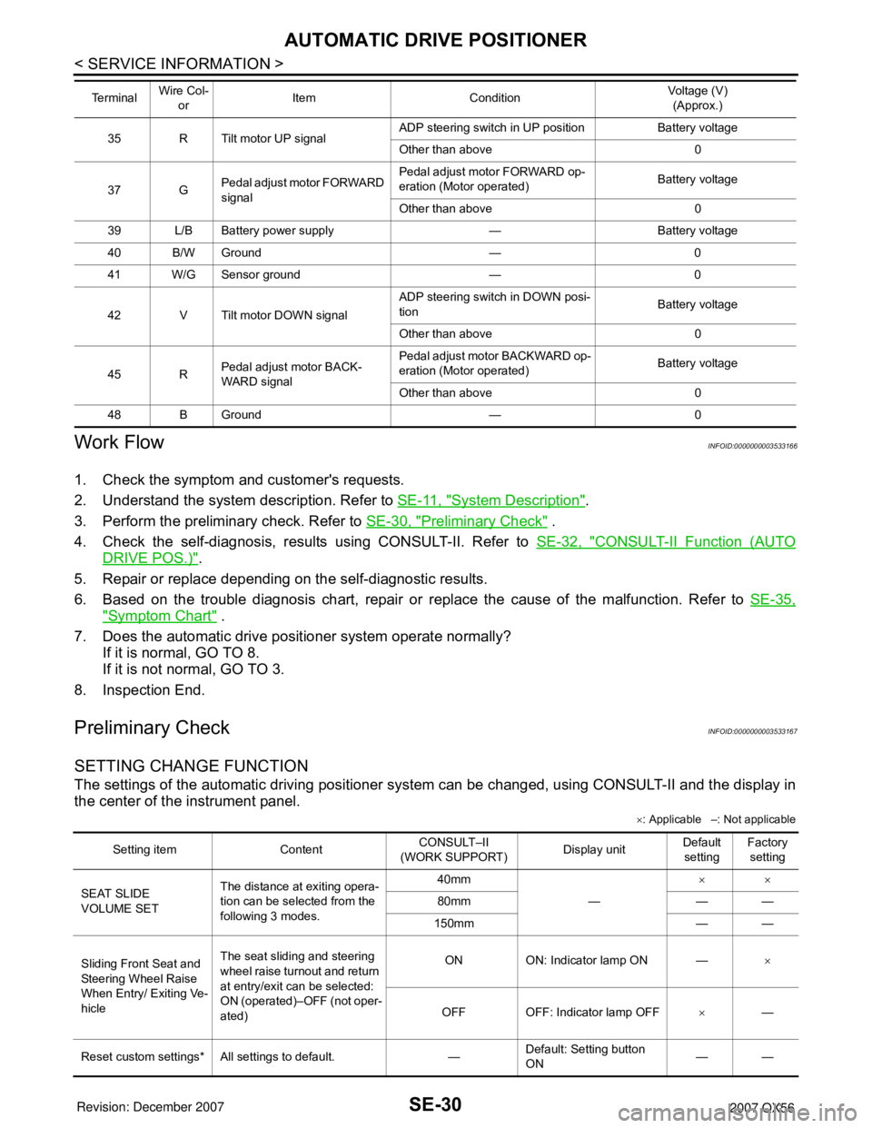
SETTING CHANGE FUNCTION
The settings of the automatic driving positioner system can be changed, using CONSULT-II and the display in
the center of the instrument panel.
×: Applicable –: Not applicable
35 R Tilt motor UP signalADP steering switch in UP position Battery voltage
Other than above 0
37 GPedal adjust motor FORWARD
signalPedal adjust motor FORWARD op-
eration (Motor operated)Battery voltage
Other than above 0
39 L/B Battery power supply — Battery voltage
40 B/W Ground — 0
41 W/G Sensor ground — 0
42 V Tilt motor DOWN signalADP steering switch in DOWN posi-
tionBattery voltage
Other than above 0
45 RPedal adjust motor BACK-
WARD signalPedal adjust motor BACKWARD op-
eration (Motor operated)Battery voltage
Other than above 0
48 B Ground — 0 Te r m i n a l Wire Col-
orItem ConditionVoltage (V)
(Approx.)
Setting item ContentCONSULT–II
(WORK SUPPORT)Display unitDefault
settingFactory
setting
SEAT SLIDE
VOLUME SETThe distance at exiting opera-
tion can be selected from the
following 3 modes.40mm
—××
80mm — —
150mm — —
Sliding Front Seat and
Steering Wheel Raise
When Entry/ Exiting Ve-
hicleThe seat sliding and steering
wheel raise turnout and return
at entry/exit can be selected:
ON (operated)–OFF (not oper-
ated)ON ON: Indicator lamp ON —×
OFF OFF: Indicator lamp OFF×—
Reset custom settings* All settings to default. —Default: Setting button
ON——
Page 2703 of 3061
AUTOMATIC DRIVE POSITIONER
SE-31
< SERVICE INFORMATION >
C
D
E
F
G
H
J
K
L
MA
B
SE
N
O
P
It is possible to set sliding front seat for entry/exit of vehicle by pressing set switch.
*: Setting of sliding front seat for entry/exit of vehicle is ON at factory-shipment. But if custom settings are reset, setting turns OFF.
NOTE:
After the setting is registered, the new setting is effective, even if the battery is disconnected.
BCM Power Supply and Ground Circuit InspectionINFOID:0000000003533168
Refer to BCS-15, "BCM Power Supply and Ground Circuit Inspection".
Power Supply and Ground Circuit InspectionINFOID:0000000003533169
1.CHECK DRIVER SEAT CONTROL UNIT FUSES AND FUSIBLE LINK
Make sure any of the following fuses in the driver seat control unit and automatic drive positioner control unit
are not blown.
OK or NG
OK >> GO TO 2.
NG >> If fuse is blown, be sure to eliminate cause of malfunction before installing new fuse.
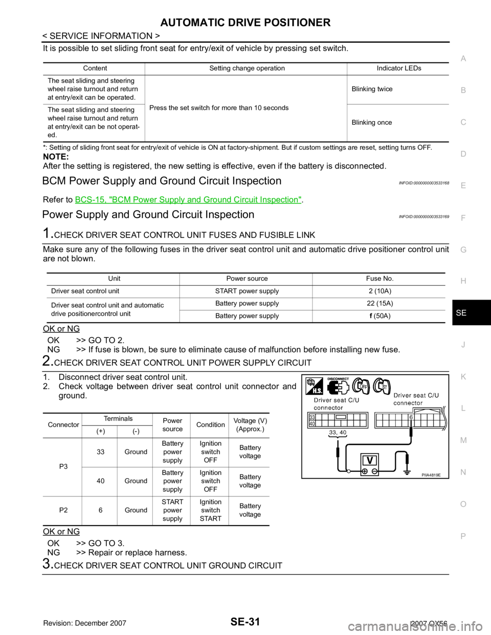
2.CHECK DRIVER SEAT CONTROL UNIT POWER SUPPLY CIRCUIT
1. Disconnect driver seat control unit.
2. Check voltage between driver seat control unit connector and
ground.
OK or NG
OK >> GO TO 3.
NG >> Repair or replace harness.
3.CHECK DRIVER SEAT CONTROL UNIT GROUND CIRCUIT
Content Setting change operation Indicator LEDs
The seat sliding and steering
wheel raise turnout and return
at entry/exit can be operated.
Press the set switch for more than 10 secondsBlinking twice
The seat sliding and steering
wheel raise turnout and return
at entry/exit can be not operat-
ed.Blinking once
Unit Power source Fuse No.
Driver seat control unit START power supply 2 (10A)
Driver seat control unit and automatic
drive positionercontrol unitBattery power supply 22 (15A)
Battery power supplyf (50A)
ConnectorTe r m i n a l s
Power
sourceConditionVoltage (V)
(Approx.)
(+) (-)
P333 GroundBattery
power
supplyIgnition
switch
OFFBattery
voltage
40 GroundBattery
power
supplyIgnition
switch
OFFBattery
voltage
P2 6 GroundSTART
power
supplyIgnition
switch
STARTBattery
voltage
PIIA4819E
Page 2856 of 3061
TF-34
< SERVICE INFORMATION >
TROUBLE DIAGNOSIS
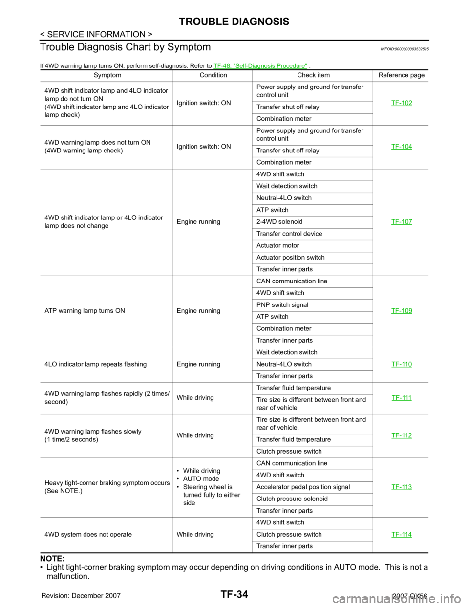
Trouble Diagnosis Chart by Symptom
INFOID:0000000003532525
If 4WD warning lamp turns ON, perform self-diagnosis. Refer to TF-48, "Self-Diagnosis Procedure" .
NOTE:
• Light tight-corner braking symptom may occur depending on driving conditions in AUTO mode. This is not a
malfunction.
Symptom Condition Check item Reference page
4WD shift indicator lamp and 4LO indicator
lamp do not turn ON
(4WD shift indicator lamp and 4LO indicator
lamp check)Ignition switch: ONPower supply and ground for transfer
control unit
TF-102
Transfer shut off relay
Combination meter
4WD warning lamp does not turn ON
(4WD warning lamp check)Ignition switch: ONPower supply and ground for transfer
control unit
TF-104
Transfer shut off relay
Combination meter
4WD shift indicator lamp or 4LO indicator
lamp does not changeEngine running4WD shift switch
TF-107
Wait detection switch
Neutral-4LO switch
ATP switch
2-4WD solenoid
Transfer control device
Actuator motor
Actuator position switch
Transfer inner parts
ATP warning lamp turns ON Engine runningCAN communication line
TF-109
4WD shift switch
PNP switch signal
ATP switch
Combination meter
Transfer inner parts
4LO indicator lamp repeats flashing Engine runningWait detection switch
TF-110
Neutral-4LO switch
Transfer inner parts
4WD warning lamp flashes rapidly (2 times/
second)While drivingTransfer fluid temperature
TF-111
Tire size is different between front and
rear of vehicle
4WD warning lamp flashes slowly
(1 time/2 seconds)While drivingTire size is different between front and
rear of vehicle.
TF-112
Transfer fluid temperature
Clutch pressure switch
Heavy tight-corner braking symptom occurs
(See NOTE.)• While driving
•AUTO mode
• Steering wheel is
turned fully to either
sideCAN communication line
TF-113
4WD shift switch
Accelerator pedal position signal
Clutch pressure solenoid
Transfer inner parts
4WD system does not operate While driving4WD shift switch
TF-114
Clutch pressure switch
Transfer inner parts
Page 2857 of 3061
TROUBLE DIAGNOSIS
TF-35
< SERVICE INFORMATION >
C
E
F
G
H
I
J
K
L
MA
B
TF
N
O
P
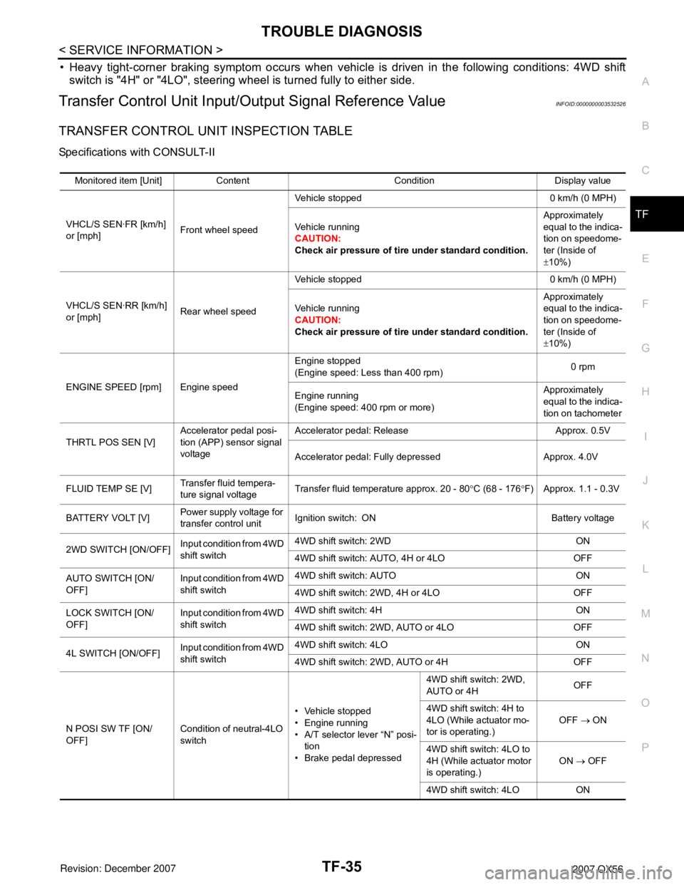
• Heavy tight-corner braking symptom occurs when vehicle is driven in the following conditions: 4WD shift
switch is "4H" or "4LO", steering wheel is turned fully to either side.
Transfer Control Unit Input/Output Signal Reference ValueINFOID:0000000003532526
TRANSFER CONTROL UNIT INSPECTION TABLE
Specifications with CONSULT-II
Monitored item [Unit] Content Condition Display value
VHCL/S SEN·FR [km/h]
or [mph]Front wheel speedVehicle stopped 0 km/h (0 MPH)
Vehicle running
CAUTION:
Check air pressure of tire under standard condition.Approximately
equal to the indica-
tion on speedome-
ter (Inside of
±10%)
VHCL/S SEN·RR [km/h]
or [mph]Rear wheel speedVehicle stopped 0 km/h (0 MPH)
Vehicle running
CAUTION:
Check air pressure of tire under standard condition.Approximately
equal to the indica-
tion on speedome-
ter (Inside of
±10%)
ENGINE SPEED [rpm] Engine speedEngine stopped
(Engine speed: Less than 400 rpm)0 rpm
Engine running
(Engine speed: 400 rpm or more)Approximately
equal to the indica-
tion on tachometer
THRTL POS SEN [V]Accelerator pedal posi-
tion (APP) sensor signal
voltageAccelerator pedal: Release Approx. 0.5V
Accelerator pedal: Fully depressed Approx. 4.0V
FLUID TEMP SE [V]Transfer fluid tempera-
ture signal voltageTransfer fluid temperature approx. 20 - 80°C (68 - 176°F) Approx. 1.1 - 0.3V
BATTERY VOLT [V]Power supply voltage for
transfer control unitIgnition switch: ON Battery voltage
2WD SWITCH [ON/OFF]Input condition from 4WD
shift switch4WD shift switch: 2WD ON
4WD shift switch: AUTO, 4H or 4LO OFF
AUTO SWITCH [ON/
OFF]Input condition from 4WD
shift switch4WD shift switch: AUTO ON
4WD shift switch: 2WD, 4H or 4LO OFF
LOCK SWITCH [ON/
OFF]Input condition from 4WD
shift switch4WD shift switch: 4H ON
4WD shift switch: 2WD, AUTO or 4LO OFF
4L SWITCH [ON/OFF]Input condition from 4WD
shift switch4WD shift switch: 4LO ON
4WD shift switch: 2WD, AUTO or 4H OFF
N POSI SW TF [ON/
OFF]Condition of neutral-4LO
switch• Vehicle stopped
• Engine running
• A/T selector lever “N” posi-
tion
• Brake pedal depressed4WD shift switch: 2WD,
AUTO or 4HOFF
4WD shift switch: 4H to
4LO (While actuator mo-
tor is operating.)OFF → ON
4WD shift switch: 4LO to
4H (While actuator motor
is operating.)ON → OFF
4WD shift switch: 4LO ON