Page 1521 of 3061
EC-438
< SERVICE INFORMATION >
DTC P0550 PSP SENSOR
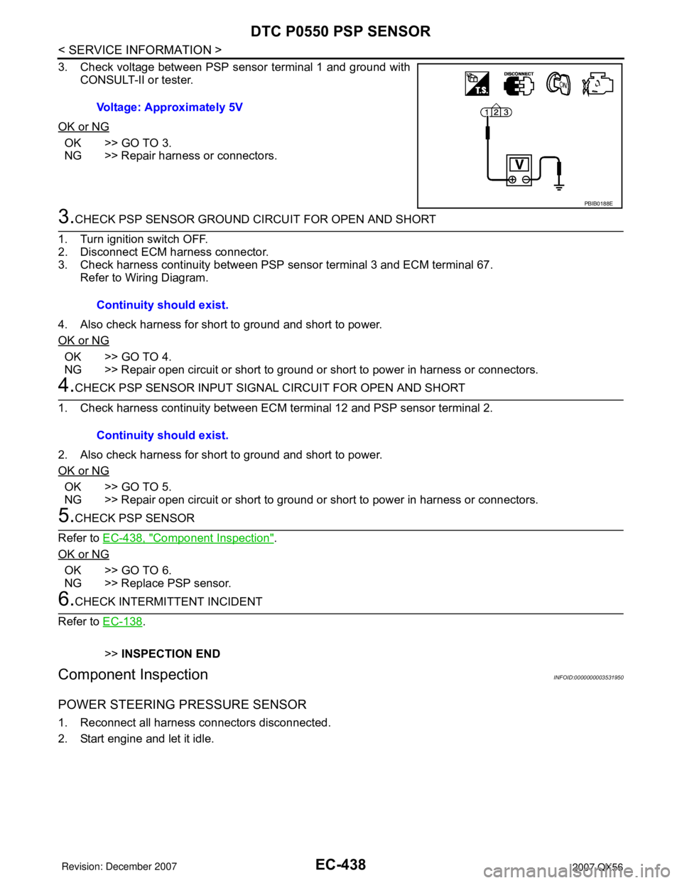
3. Check voltage between PSP sensor terminal 1 and ground with
CONSULT-II or tester.
OK or NG
OK >> GO TO 3.
NG >> Repair harness or connectors.
3.CHECK PSP SENSOR GROUND CIRCUIT FOR OPEN AND SHORT
1. Turn ignition switch OFF.
2. Disconnect ECM harness connector.
3. Check harness continuity between PSP sensor terminal 3 and ECM terminal 67.
Refer to Wiring Diagram.
4. Also check harness for short to ground and short to power.
OK or NG
OK >> GO TO 4.
NG >> Repair open circuit or short to ground or short to power in harness or connectors.
4.CHECK PSP SENSOR INPUT SIGNAL CIRCUIT FOR OPEN AND SHORT
1. Check harness continuity between ECM terminal 12 and PSP sensor terminal 2.
2. Also check harness for short to ground and short to power.
OK or NG
OK >> GO TO 5.
NG >> Repair open circuit or short to ground or short to power in harness or connectors.
5.CHECK PSP SENSOR
Refer to EC-438, "
Component Inspection".
OK or NG
OK >> GO TO 6.
NG >> Replace PSP sensor.
6.CHECK INTERMITTENT INCIDENT
Refer to EC-138
.
>>INSPECTION END
Component InspectionINFOID:0000000003531950
POWER STEERING PRESSURE SENSOR
1. Reconnect all harness connectors disconnected.
2. Start engine and let it idle.Voltage: Approximately 5V
PBIB0188E
Continuity should exist.
Continuity should exist.
Page 1522 of 3061
DTC P0550 PSP SENSOR
EC-439
< SERVICE INFORMATION >
C
D
E
F
G
H
I
J
K
L
MA
EC
N
P O
3. Check voltage between ECM terminal 12 and ground under the
following conditions.
Removal and InstallationINFOID:0000000003531951
POWER STEERING PRESSURE SENSOR
Refer to PS-23.
Condition Voltage
Steering wheel: Being turned. 0.5 - 4.5V
Steering wheel: Not being turned. 0.4 - 0.8V
MBIB0126E
Page 1530 of 3061
DTC P0643 SENSOR POWER SUPPLY
EC-447
< SERVICE INFORMATION >
C
D
E
F
G
H
I
J
K
L
MA
EC
N
P O
DTC P0643 SENSOR POWER SUPPLY
On Board Diagnosis LogicINFOID:0000000003531961
This self-diagnosis has the one trip detection logic.
FA I L - S A F E M O D E
When the malfunction is detected, ECM enters fail-safe mode and the MIL lights up.
DTC Confirmation ProcedureINFOID:0000000003531962
NOTE:
If DTC Confirmation Procedure has been previously conducted, always turn ignition switch OFF and wait at
least 10 seconds before conducting the next test.
TESTING CONDITION:
Before performing the following procedure, confirm that battery voltage is more than 10V at idle.
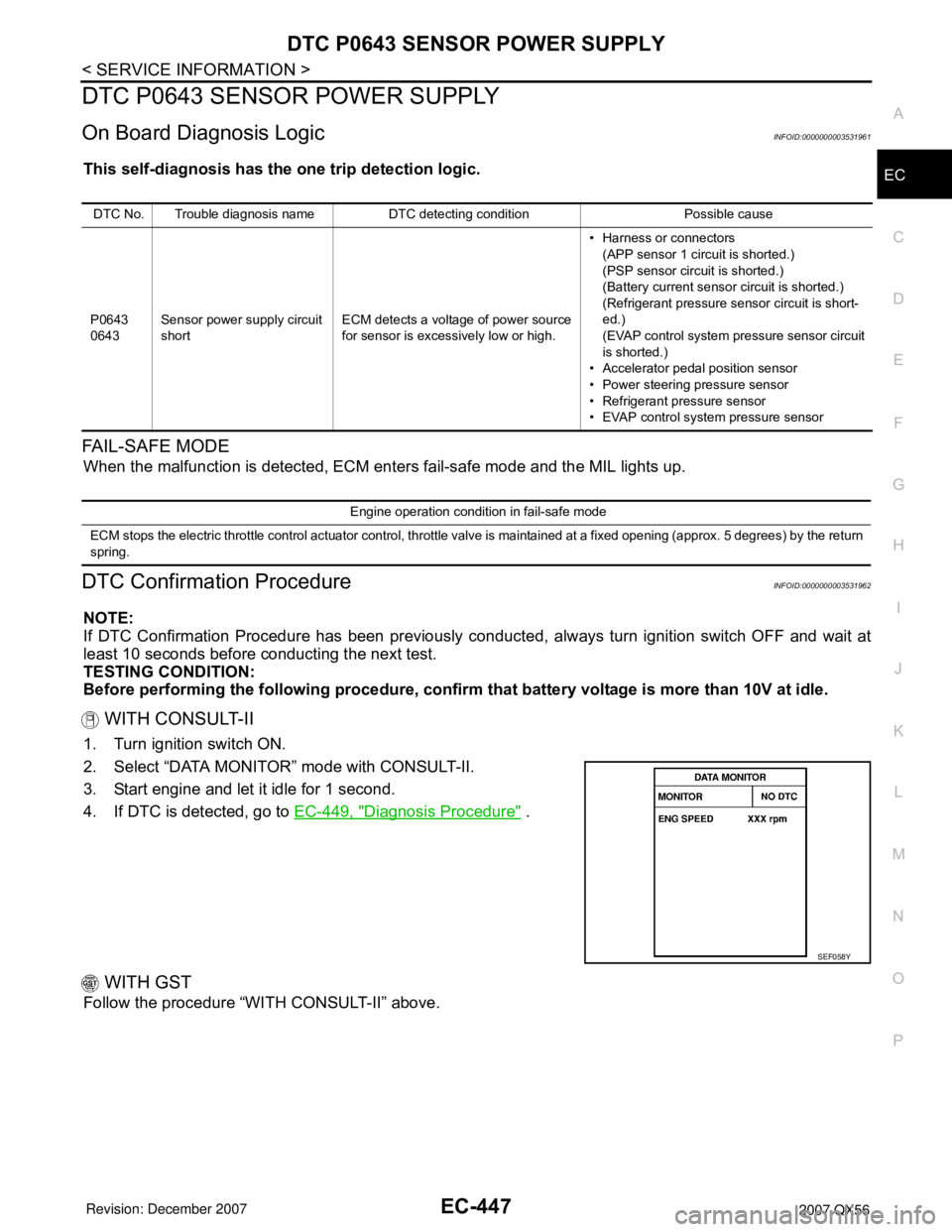
WITH CONSULT-II
1. Turn ignition switch ON.
2. Select “DATA MONITOR” mode with CONSULT-II.
3. Start engine and let it idle for 1 second.
4. If DTC is detected, go to EC-449, "
Diagnosis Procedure" .
WITH GST
Follow the procedure “WITH CONSULT-II” above.
DTC No. Trouble diagnosis name DTC detecting condition Possible cause
P0643
0643Sensor power supply circuit
shortECM detects a voltage of power source
for sensor is excessively low or high.• Harness or connectors
(APP sensor 1 circuit is shorted.)
(PSP sensor circuit is shorted.)
(Battery current sensor circuit is shorted.)
(Refrigerant pressure sensor circuit is short-
ed.)
(EVAP control system pressure sensor circuit
is shorted.)
• Accelerator pedal position sensor
• Power steering pressure sensor
• Refrigerant pressure sensor
• EVAP control system pressure sensor
Engine operation condition in fail-safe mode
ECM stops the electric throttle control actuator control, throttle valve is maintained at a fixed opening (approx. 5 degrees) by the return
spring.
SEF058Y
Page 1532 of 3061
DTC P0643 SENSOR POWER SUPPLY
EC-449
< SERVICE INFORMATION >
C
D
E
F
G
H
I
J
K
L
MA
EC
N
P O
Diagnosis ProcedureINFOID:0000000003531964
1.CHECK GROUND CONNECTIONS
1. Turn ignition switch OFF.
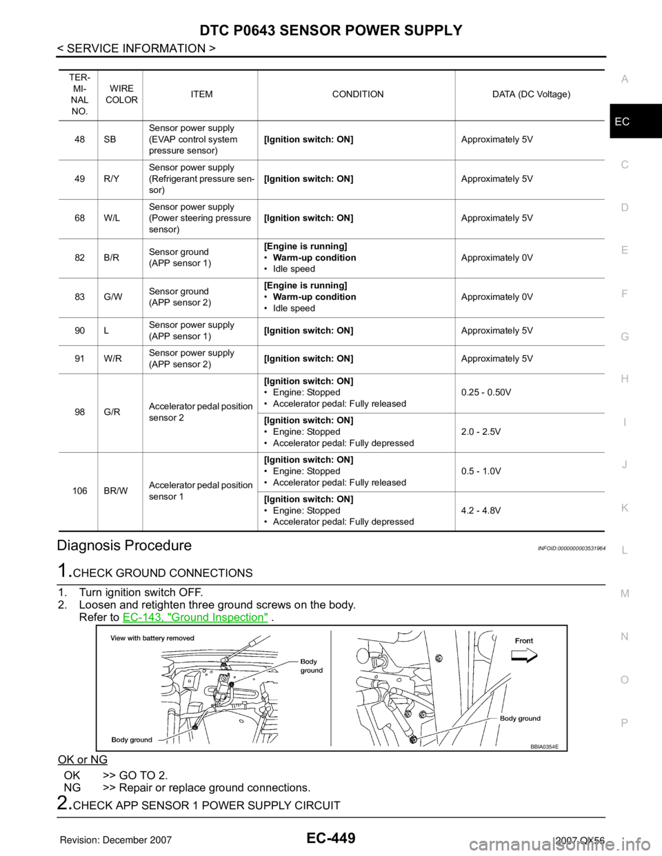
2. Loosen and retighten three ground screws on the body.
Refer to EC-143, "
Ground Inspection" .
OK or NG
OK >> GO TO 2.
NG >> Repair or replace ground connections.
2.CHECK APP SENSOR 1 POWER SUPPLY CIRCUIT
TER-
MI-
NAL
NO.WIRE
COLORITEM CONDITION DATA (DC Voltage)
48 SBSensor power supply
(EVAP control system
pressure sensor)[Ignition switch: ON]Approximately 5V
49 R/YSensor power supply
(Refrigerant pressure sen-
sor)[Ignition switch: ON]Approximately 5V
68 W/LSensor power supply
(Power steering pressure
sensor)[Ignition switch: ON]Approximately 5V
82 B/RSensor ground
(APP sensor 1)[Engine is running]
•Warm-up condition
• Idle speedApproximately 0V
83 G/WSensor ground
(APP sensor 2)[Engine is running]
•Warm-up condition
• Idle speedApproximately 0V
90 LSensor power supply
(APP sensor 1)[Ignition switch: ON]Approximately 5V
91 W/RSensor power supply
(APP sensor 2)[Ignition switch: ON]Approximately 5V
98 G/RAccelerator pedal position
sensor 2[Ignition switch: ON]
• Engine: Stopped
• Accelerator pedal: Fully released0.25 - 0.50V
[Ignition switch: ON]
• Engine: Stopped
• Accelerator pedal: Fully depressed2.0 - 2.5V
106 BR/WAccelerator pedal position
sensor 1[Ignition switch: ON]
• Engine: Stopped
• Accelerator pedal: Fully released0.5 - 1.0V
[Ignition switch: ON]
• Engine: Stopped
• Accelerator pedal: Fully depressed4.2 - 4.8V
BBIA0354E
Page 1533 of 3061
EC-450
< SERVICE INFORMATION >
DTC P0643 SENSOR POWER SUPPLY
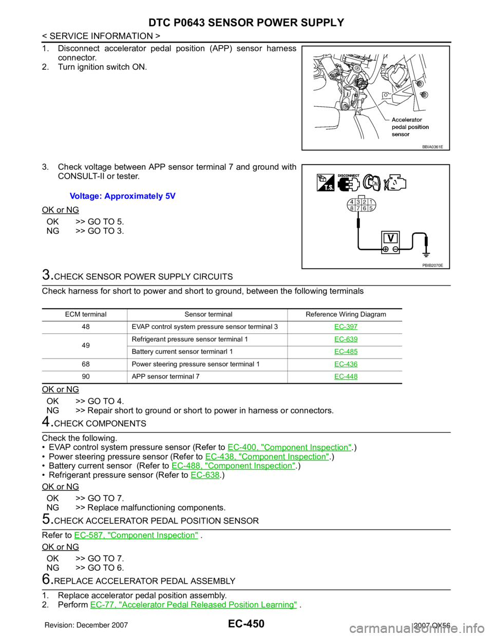
1. Disconnect accelerator pedal position (APP) sensor harness
connector.
2. Turn ignition switch ON.
3. Check voltage between APP sensor terminal 7 and ground with
CONSULT-II or tester.
OK or NG
OK >> GO TO 5.
NG >> GO TO 3.
3.CHECK SENSOR POWER SUPPLY CIRCUITS
Check harness for short to power and short to ground, between the following terminals
OK or NG
OK >> GO TO 4.
NG >> Repair short to ground or short to power in harness or connectors.
4.CHECK COMPONENTS
Check the following.
• EVAP control system pressure sensor (Refer to EC-400, "
Component Inspection".)
• Power steering pressure sensor (Refer to EC-438, "
Component Inspection".)
• Battery current sensor (Refer to EC-488, "
Component Inspection".)
• Refrigerant pressure sensor (Refer to EC-638
.)
OK or NG
OK >> GO TO 7.
NG >> Replace malfunctioning components.
5.CHECK ACCELERATOR PEDAL POSITION SENSOR
Refer to EC-587, "
Component Inspection" .
OK or NG
OK >> GO TO 7.
NG >> GO TO 6.
6.REPLACE ACCELERATOR PEDAL ASSEMBLY
1. Replace accelerator pedal position assembly.
2. Perform EC-77, "
Accelerator Pedal Released Position Learning" .
BBIA0361E
Voltage: Approximately 5V
PBIB2070E
ECM terminal Sensor terminal Reference Wiring Diagram
48 EVAP control system pressure sensor terminal 3EC-397
49Refrigerant pressure sensor terminal 1EC-639Battery current sensor terminarl 1EC-485
68 Power steering pressure sensor terminal 1EC-436
90 APP sensor terminal 7EC-448
Page 1594 of 3061
DTC P1564 ICC STEERING SWITCH
EC-511
< SERVICE INFORMATION >
C
D
E
F
G
H
I
J
K
L
MA
EC
N
P O
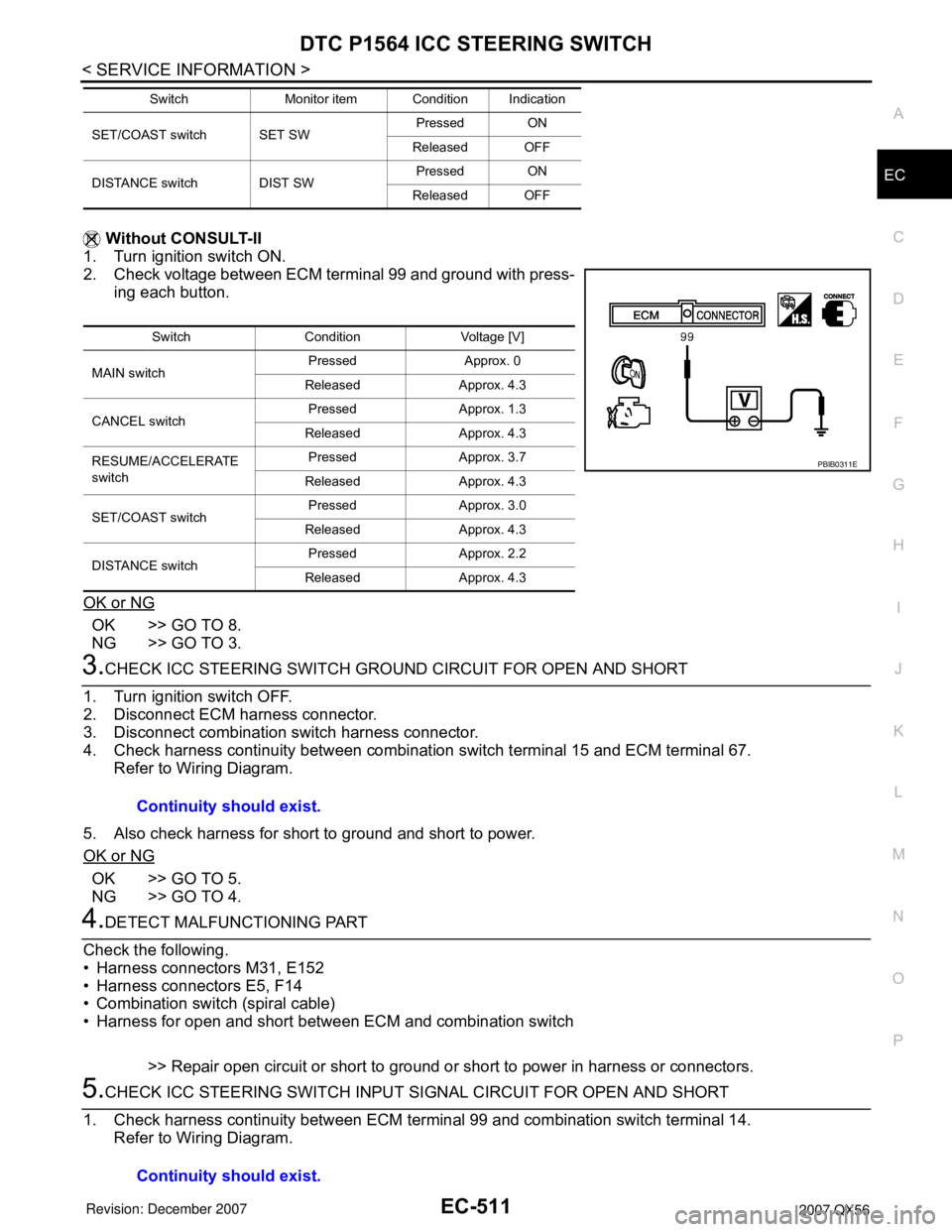
Without CONSULT-II
1. Turn ignition switch ON.
2. Check voltage between ECM terminal 99 and ground with press-
ing each button.
OK or NG
OK >> GO TO 8.
NG >> GO TO 3.
3.CHECK ICC STEERING SWITCH GROUND CIRCUIT FOR OPEN AND SHORT
1. Turn ignition switch OFF.
2. Disconnect ECM harness connector.
3. Disconnect combination switch harness connector.
4. Check harness continuity between combination switch terminal 15 and ECM terminal 67.
Refer to Wiring Diagram.
5. Also check harness for short to ground and short to power.
OK or NG
OK >> GO TO 5.
NG >> GO TO 4.
4.DETECT MALFUNCTIONING PART
Check the following.
• Harness connectors M31, E152
• Harness connectors E5, F14
• Combination switch (spiral cable)
• Harness for open and short between ECM and combination switch
>> Repair open circuit or short to ground or short to power in harness or connectors.
5.CHECK ICC STEERING SWITCH INPUT SIGNAL CIRCUIT FOR OPEN AND SHORT
1. Check harness continuity between ECM terminal 99 and combination switch terminal 14.
Refer to Wiring Diagram.
SET/COAST switch SET SWPressed ON
Released OFF
DISTANCE switch DIST SWPressed ON
Released OFF Switch Monitor item Condition Indication
Switch Condition Voltage [V]
MAIN switchPressed Approx. 0
Released Approx. 4.3
CANCEL switchPressed Approx. 1.3
Released Approx. 4.3
RESUME/ACCELERATE
switchPressed Approx. 3.7
Released Approx. 4.3
SET/COAST switchPressed Approx. 3.0
Released Approx. 4.3
DISTANCE switchPressed Approx. 2.2
Released Approx. 4.3
PBIB0311E
Continuity should exist.
Continuity should exist.
Page 1595 of 3061
EC-512
< SERVICE INFORMATION >
DTC P1564 ICC STEERING SWITCH
2. Also check harness for short to ground and short to power.
OK or NG
OK >> GO TO 7.
NG >> GO TO 6.
6.DETECT MALFUNCTIONING PART
Check the following.
• Harness connectors M31, E152
• Combination switch (spiral cable)
• Harness for open and short between ECM and combination switch
>> Repair open circuit or short to ground or short to power in harness or connectors.
7.CHECK ICC STEERING SWITCH
Refer to EC-512, "
Component Inspection".
OK or NG
OK >> GO TO 8.
NG >> Replace ICC steering switch.
8.CHECK INTERMITTENT INCIDENT
Refer to EC-138
.
>>INSPECTION END
Component InspectionINFOID:0000000003532045
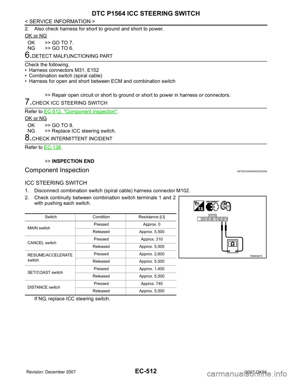
ICC STEERING SWITCH
1. Disconnect combination switch (spiral cable) harness connector M102.
2. Check continuity between combination switch terminals 1 and 2
with pushing each switch.
If NG, replace ICC steering switch.
Switch Condition Resistance [Ω]
MAIN switchPressed Approx. 0
Released Approx. 5,500
CANCEL switchPressed Approx. 310
Released Approx. 5,500
RESUME/ACCELERATE
switchPressed Approx. 2,600
Released Approx. 5,500
SET/COAST switchPressed Approx. 1,400
Released Approx. 5,500
DISTANCE switchPressed Approx. 740
Released Approx. 5,500
PBIB0967E
Page 1600 of 3061
DTC P1564 ASCD STEERING SWITCH
EC-517
< SERVICE INFORMATION >
C
D
E
F
G
H
I
J
K
L
MA
EC
N
P O
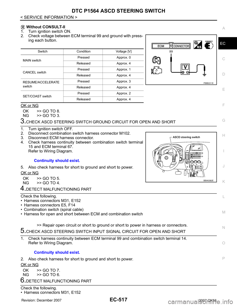
Without CONSULT-II
1. Turn ignition switch ON.
2. Check voltage between ECM terminal 99 and ground with press-
ing each button.
OK or NG
OK >> GO TO 8.
NG >> GO TO 3.
3.CHECK ASCD STEERING SWITCH GROUND CIRCUIT FOR OPEN AND SHORT
1. Turn ignition switch OFF.
2. Disconnect combination switch harness connector M102.
3. Disconnect ECM harness connector.
4. Check harness continuity between combination switch terminal
15 and ECM terminal 67.
Refer to Wiring Diagram.
5. Also check harness for short to ground and short to power.
OK or NG
OK >> GO TO 5.
NG >> GO TO 4.
4.DETECT MALFUNCTIONING PART
Check the following.
• Harness connectors M31, E152
• Harness connectors E5, F14
• Combination switch (spiral cable)
• Harness for open and short between ECM and combination switch
>> Repair open circuit or short to ground or short to power in harness or connectors.
5.CHECK ASCD STEERING SWITCH INPUT SIGNAL CIRCUIT FOR OPEN AND SHORT
1. Check harness continuity between ECM terminal 99 and combination switch terminal 14.
Refer to Wiring Diagram.
2. Also check harness for short to ground and short to power.
OK or NG
OK >> GO TO 7.
NG >> GO TO 6.
6.DETECT MALFUNCTIONING PART
Check the following.
• Harness connectors M31, E152
Switch Condition Voltage [V]
MAIN switchPressed Approx. 0
Released Approx. 4
CANCEL switchPressed Approx. 1
Released Approx. 4
RESUME/ACCELERATE
switchPressed Approx. 3
Released Approx. 4
SET/COAST switchPressed Approx. 2
Released Approx. 4
PBIB0311E
Continuity should exist.
BBIA0362E
Continuity should exist.