2007 INFINITI QX56 turn signal
[x] Cancel search: turn signalPage 2745 of 3061
AUTOMATIC DRIVE POSITIONER
SE-73
< SERVICE INFORMATION >
C
D
E
F
G
H
J
K
L
MA
B
SE
N
O
P
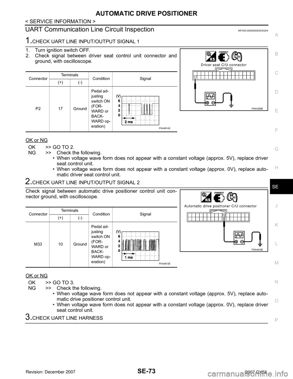
UART Communication Line Circuit InspectionINFOID:0000000003533204
1.CHECK UART LINE INPUT/OUTPUT SIGNAL 1
1. Turn ignition switch OFF.
2. Check signal between driver seat control unit connector and
ground, with oscilloscope.
OK or NG
OK >> GO TO 2.
NG >> Check the following.
• When voltage wave form does not appear with a constant voltage (approx. 5V), replace driver
seat control unit.
• When voltage wave form does not appear with a constant voltage (approx. 0V), replace auto-
matic driver seat control unit.
2.CHECK UART LINE INPUT/OUTPUT SIGNAL 2
Check signal between automatic drive positioner control unit con-
nector ground, with oscilloscope.
OK or NG
OK >> GO TO 3.
NG >> Check the following.
• When voltage wave form does not appear with a constant voltage (approx. 5V), replace auto-
matic drive positioner control unit.
• When voltage wave form does not appear with a constant voltage (approx. 0V), replace driver
seat control unit.
3.CHECK UART LINE HARNESS
ConnectorTe r m i n a l s
Condition Signal
(+) (-)
P2 17 GroundPedal ad-
justing
switch ON
(FOR-
WARD or
BACK-
WARD op-
eration)
PIIA4599E
PIIA4814E
ConnectorTe r m i n a l s
Condition Signal
(+) (-)
M33 10 GroundPedal ad-
justing
switch ON
(FOR-
WARD or
BACK-
WARD op-
eration)
PIIA4816E
PIIA4813E
Page 2788 of 3061
SRS-18
< SERVICE INFORMATION >
TROUBLE DIAGNOSIS
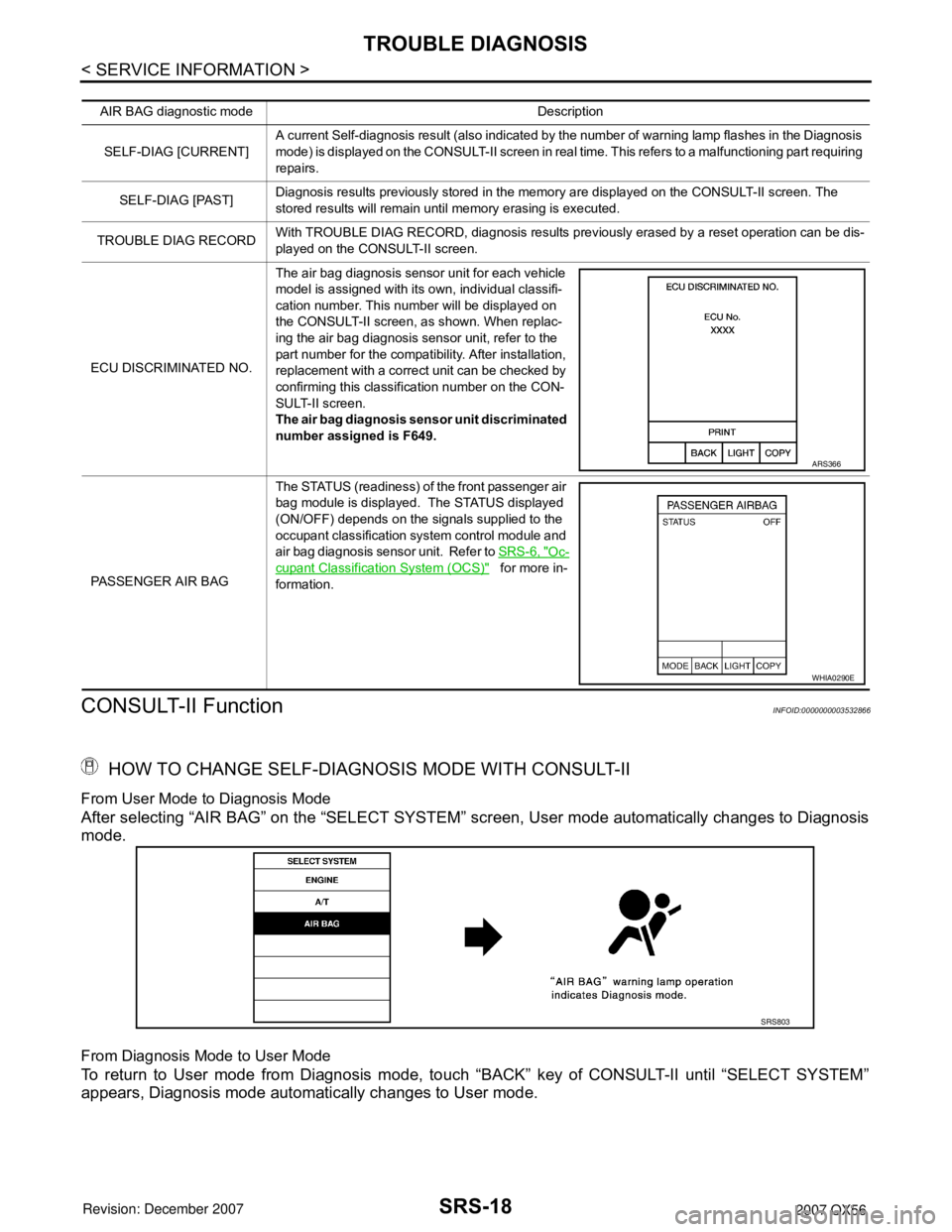
CONSULT-II Function
INFOID:0000000003532866
HOW TO CHANGE SELF-DIAGNOSIS MODE WITH CONSULT-II
From User Mode to Diagnosis Mode
After selecting “AIR BAG” on the “SELECT SYSTEM” screen, User mode automatically changes to Diagnosis
mode.
From Diagnosis Mode to User Mode
To return to User mode from Diagnosis mode, touch “BACK” key of CONSULT-II until “SELECT SYSTEM”
appears, Diagnosis mode automatically changes to User mode.
AIR BAG diagnostic mode Description
SELF-DIAG [CURRENT]A current Self-diagnosis result (also indicated by the number of warning lamp flashes in the Diagnosis
mode) is displayed on the CONSULT-II screen in real time. This refers to a malfunctioning part requiring
repairs.
SELF-DIAG [PAST]Diagnosis results previously stored in the memory are displayed on the CONSULT-II screen. The
stored results will remain until memory erasing is executed.
TROUBLE DIAG RECORDWith TROUBLE DIAG RECORD, diagnosis results previously erased by a reset operation can be dis-
played on the CONSULT-II screen.
ECU DISCRIMINATED NO.The air bag diagnosis sensor unit for each vehicle
model is assigned with its own, individual classifi-
cation number. This number will be displayed on
the CONSULT-II screen, as shown. When replac-
ing the air bag diagnosis sensor unit, refer to the
part number for the compatibility. After installation,
replacement with a correct unit can be checked by
confirming this classification number on the CON-
SULT-II screen.
The air bag diagnosis sensor unit discriminated
number assigned is F649.
PASSENGER AIR BAGThe STATUS (readiness) of the front passenger air
bag module is displayed. The STATUS displayed
(ON/OFF) depends on the signals supplied to the
occupant classification system control module and
air bag diagnosis sensor unit. Refer to SRS-6, "
Oc-
cupant Classification System (OCS)" for more in-
formation.
ARS366
WHIA0290E
SRS803
Page 2807 of 3061
SPIRAL CABLE
SRS-37
< SERVICE INFORMATION >
C
D
E
F
G
I
J
K
L
MA
B
SRS
N
O
P
SPIRAL CABLE
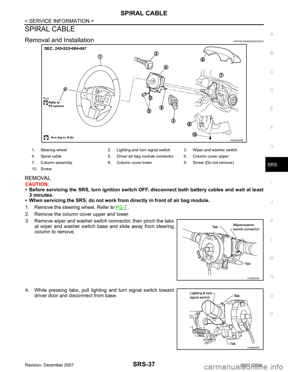
Removal and InstallationINFOID:0000000003532874
REMOVAL
CAUTION:
• Before servicing the SRS, turn ignition switch OFF, disconnect both battery cables and wait at least
3 minutes.
• When servicing the SRS, do not work from directly in front of air bag module.
1. Remove the steering wheel. Refer to PS-7
.
2. Remove the column cover upper and lower.
3. Remove wiper and washer switch connector, then pinch the tabs
at wiper and washer switch base and slide away from steering
column to remove.
4. While pressing tabs, pull lighting and turn signal switch toward
driver door and disconnect from base.
WHIA0233E
1. Steering wheel 2. Lighting and turn signal switch 3. Wiper and washer switch
4. Spiral cable 5. Driver air bag module connector 6. Column cover upper
7. Column assembly 8. Column cover lower 9. Screw (Do not remove)
10. Screw
LHIA0034E
LHIA0035E
Page 2823 of 3061

TF-1
DRIVELINE/AXLE
C
E
F
G
H
I
J
K
L
M
SECTION TF
A
B
TF
N
O
P
CONTENTS
TRANSFER
SERVICE INFORMATION ............................3
PRECAUTIONS ...................................................3
Precaution for Supplemental Restraint System
(SRS) "AIR BAG" and "SEAT BELT PRE-TEN-
SIONER" ...................................................................
3
Precaution for Transfer Assembly and Transfer
Control Unit Replacement .........................................
3
Precaution .................................................................4
Service Notice ...........................................................4
PREPARATION ...................................................6
Special Service Tool .................................................6
Commercial Service Tool ..........................................9
NOISE, VIBRATION AND HARSHNESS
(NVH) TROUBLESHOOTING ............................
10
NVH Troubleshooting Chart ....................................10
TRANSFER FLUID .............................................11
Replacement ...........................................................11
Inspection ................................................................11
ALL-MODE 4WD SYSTEM ................................12
Cross-Sectional View ..............................................12
Power Transfer ........................................................12
System Description .................................................14
Schematic ...............................................................19
CAN Communication ...............................................20
TROUBLE DIAGNOSIS .....................................21
How to Perform Trouble Diagnosis .........................21
Location of Electrical Parts ......................................22
Circuit Diagram .......................................................23
Wiring Diagram - T/F - .............................................24
Inspections Before Trouble Diagnosis ....................31
Trouble Diagnosis Chart by Symptom ....................34
Transfer Control Unit Input/Output Signal Refer-
ence Value ..............................................................
35
CONSULT-II Function (ALL MODE AWD/4WD) .....42
Self-Diagnosis Procedure .......................................48
TROUBLE DIAGNOSIS FOR SYSTEM ............51
Power Supply Circuit for Transfer Control Unit ........51
Transfer Control Unit ...............................................53
Output Shaft Revolution Signal (TCM) ....................53
Vehicle Speed Sensor (ABS) ..................................54
Neutral-4LO Switch .................................................54
4WD Shift Switch .....................................................57
Wait Detection Switch ..............................................60
PNP Switch Signal (TCM) .......................................63
Actuator Motor .........................................................64
Actuator Position Switch ..........................................69
Transfer Control Device ...........................................72
Engine Speed Signal (ECM) ....................................76
Clutch Pressure Solenoid ........................................76
2-4WD Solenoid ......................................................80
Transfer Motor .........................................................84
Transfer Fluid Temperature .....................................90
Clutch Pressure Switch ...........................................92
Line Pressure Switch ...............................................94
Throttle Position Signal (ECM) ................................97
ABS Operation Signal (ABS) ...................................97
VDC Operation Signal (ABS) ...................................98
TCS Operation Signal (ABS) ...................................98
CAN Communication Line .......................................99
ATP Switch ..............................................................99
TROUBLE DIAGNOSIS FOR SYMPTOMS ....102
4WD Shift Indicator Lamp and 4LO Indicator
Lamp Do Not Turn ON ...........................................
102
4WD Warning Lamp Does Not Turn ON ...............104
4WD Shift Indicator Lamp or 4LO Indicator Lamp
Does Not Change ..................................................
107
ATP Warning Lamp Turns ON ...............................109
4LO Indicator Lamp Repeats Flashing ..................110
4WD Warning Lamp Flashes Rapidly ....................111
4WD Warning Lamp Flashes Slowly .....................112
Heavy Tight-corner Braking Symptom Occurs ......113
4WD System Does Not Operate ............................114
TRANSFER CONTROL UNIT .........................115
Removal and Installation .......................................115
Page 2826 of 3061
TF-4
< SERVICE INFORMATION >
PRECAUTIONS
Precaution
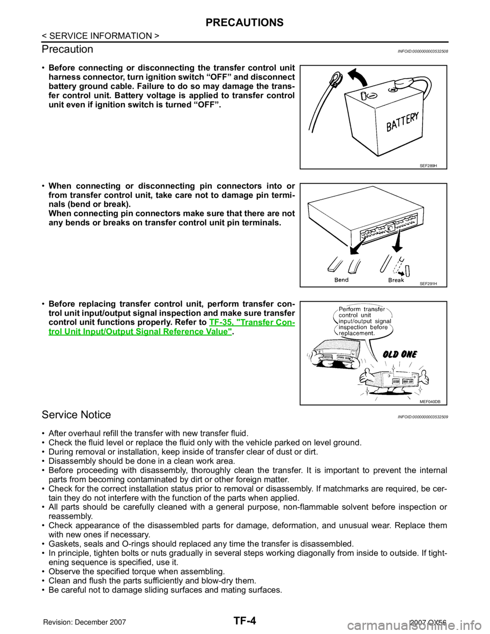
INFOID:0000000003532508
•Before connecting or disconnecting the transfer control unit
harness connector, turn ignition switch “OFF” and disconnect
battery ground cable. Failure to do so may damage the trans-
fer control unit. Battery voltage is applied to transfer control
unit even if ignition switch is turned “OFF”.
•When connecting or disconnecting pin connectors into or
from transfer control unit, take care not to damage pin termi-
nals (bend or break).
When connecting pin connectors make sure that there are not
any bends or breaks on transfer control unit pin terminals.
•Before replacing transfer control unit, perform transfer con-
trol unit input/output signal inspection and make sure transfer
control unit functions properly. Refer to TF-35, "
Transfer Con-
trol Unit Input/Output Signal Reference Value".
Service NoticeINFOID:0000000003532509
• After overhaul refill the transfer with new transfer fluid.
• Check the fluid level or replace the fluid only with the vehicle parked on level ground.
• During removal or installation, keep inside of transfer clear of dust or dirt.
• Disassembly should be done in a clean work area.
• Before proceeding with disassembly, thoroughly clean the transfer. It is important to prevent the internal
parts from becoming contaminated by dirt or other foreign matter.
• Check for the correct installation status prior to removal or disassembly. If matchmarks are required, be cer-
tain they do not interfere with the function of the parts when applied.
• All parts should be carefully cleaned with a general purpose, non-flammable solvent before inspection or
reassembly.
• Check appearance of the disassembled parts for damage, deformation, and unusual wear. Replace them
with new ones if necessary.
• Gaskets, seals and O-rings should replaced any time the transfer is disassembled.
• In principle, tighten bolts or nuts gradually in several steps working diagonally from inside to outside. If tight-
ening sequence is specified, use it.
• Observe the specified torque when assembling.
• Clean and flush the parts sufficiently and blow-dry them.
• Be careful not to damage sliding surfaces and mating surfaces.
SEF289H
SEF291H
MEF040DB
Page 2840 of 3061

TF-18
< SERVICE INFORMATION >
ALL-MODE 4WD SYSTEM
LINE PRESSURE SWITCH
• With the transfer system design, control of the oil pressure provides the transmission of drive torque to the
front wheels. The main pressure to control the oil pressure is referred to as the line pressure.
• The line pressure switch determines whether or not adequate line pressure has built up under different oper-
ating conditions.
• The line pressure switch turns ON when line pressure is produced.
• The line pressure switch senses line pressure abnormalities and turns the 4WD warning lamp ON.
CLUTCH PRESSURE SWITCH
• The clutch pressure switch determines whether or not adequate clutch pressure has built up under different
operating conditions.
• The clutch pressure switch turns ON when clutch pressure is produced.
• The clutch pressure switch senses clutch pressure abnormalities and turns the 4WD warning lamp ON.
TRANSFER FLUID TEMPERATURE SENSOR
The transfer temperature sensor detects the transfer fluid temperature and sends a signal to the transfer con-
trol unit.
TRANSFER CONTROL UNIT
• Transfer control unit controls transfer control device by input signals of each sensor and each switch.
• Self-diagnosis can be done.
TRANSFER CONTROL DEVICE
The transfer control device changes the state of transfer assembly between 2WD, AUTO, 4H⇔4LO with the
2WD, AUTO, 4H and 4LO signals of 4WD shift switch.
NOTE:
• To shift between 4H⇔4LO, stop the vehicle, depress the brake pedal and shift the transmission selector to
the "N" position. Depress and turn the 4WD shift switch. The shift switch will not shift to the desired mode if
the transmission is not in "N" or the vehicle is moving. The 4LO indicator lamp will be lit when the 4LO is
engaged.
• Actuator motor and actuator position switch are integrated.
4WD SHIFT SWITCH AND INDICATOR LAMP
4WD Shift Switch
The 4WD shift switch allows selection from 2WD, AUTO, 4H or 4LO.
4WD Shift Indicator Lamp
• Displays driving conditions selected by 4WD shift switch with 2WD, AUTO and 4H indicators while engine is
running. (When 4WD warning lamp is turned on, all 4WD shift indicator lamps are turned off.)
• Turns ON for approximately 1 second when ignition switch is turned ON, for purpose of lamp check.
4LO Indicator Lamp
• Displays 4LO condition while engine is running. 4LO indicator lamp flashes if transfer gear does not shift
completely under 2WD, AUTO, 4H⇔4LO. (When 4WD warning lamp is turned on, 4LO indicator lamp is
turned off.)
• Turns ON for approximately 1 second when ignition switch is turned ON, for purpose of lamp check.
4WD WARNING LAMP
Turns ON or FLASH when there is a malfunction in 4WD system.
Also turns ON when ignition switch is turned ON, for purpose of lamp check. Turns OFF for approximately 1
second after the engine starts if system is normal.
4WD Warning Lamp Indication
Condition Content 4WD warning lamp
During self-diagnosis Indicates the malfunction position by number of flickers. Flickers at malfunction mode.
Lamp check*Checks the lamp by turning ON during engine starting. After
engine starts, it turns OFF if there are no malfunctions.ON
Malfunction in 4WD system*Turns ON to indicate malfunction. When ignition switch is
turned to “OFF” or the malfunction is corrected, it turns OFF.ON
When vehicle is driven with different
diameters of front and rear tiresFlickers once every 2 seconds.
Turns OFF when ignition switch is “OFF”.Flickers once every 2 sec-
onds.
Page 2855 of 3061
TROUBLE DIAGNOSIS
TF-33
< SERVICE INFORMATION >
C
E
F
G
H
I
J
K
L
MA
B
TF
N
O
P
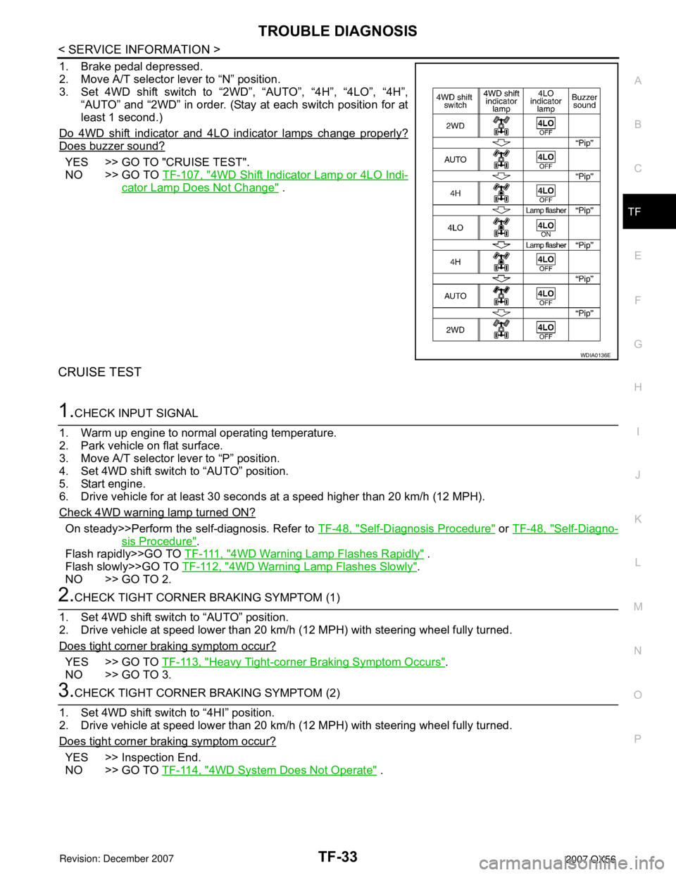
1. Brake pedal depressed.
2. Move A/T selector lever to “N” position.
3. Set 4WD shift switch to “2WD”, “AUTO”, “4H”, “4LO”, “4H”,
“AUTO” and “2WD” in order. (Stay at each switch position for at
least 1 second.)
Do 4WD shift indicator and 4LO indicator lamps change properly?
Does buzzer sound?
YES >> GO TO "CRUISE TEST".
NO >> GO TO TF-107, "
4WD Shift Indicator Lamp or 4LO Indi-
cator Lamp Does Not Change" .
CRUISE TEST
1.CHECK INPUT SIGNAL
1. Warm up engine to normal operating temperature.
2. Park vehicle on flat surface.
3. Move A/T selector lever to “P” position.
4. Set 4WD shift switch to “AUTO” position.
5. Start engine.
6. Drive vehicle for at least 30 seconds at a speed higher than 20 km/h (12 MPH).
Check 4WD warning lamp turned ON?
On steady>>Perform the self-diagnosis. Refer to TF-48, "Self-Diagnosis Procedure" or TF-48, "Self-Diagno-
sis Procedure".
Flash rapidly>>GO TO T F - 111 , "
4WD Warning Lamp Flashes Rapidly" .
Flash slowly>>GO TO TF-112, "
4WD Warning Lamp Flashes Slowly".
NO >> GO TO 2.
2.CHECK TIGHT CORNER BRAKING SYMPTOM (1)
1. Set 4WD shift switch to “AUTO” position.
2. Drive vehicle at speed lower than 20 km/h (12 MPH) with steering wheel fully turned.
Does tight corner braking symptom occur?
YES >> GO TO TF-113, "Heavy Tight-corner Braking Symptom Occurs".
NO >> GO TO 3.
3.CHECK TIGHT CORNER BRAKING SYMPTOM (2)
1. Set 4WD shift switch to “4HI” position.
2. Drive vehicle at speed lower than 20 km/h (12 MPH) with steering wheel fully turned.
Does tight corner braking symptom occur?
YES >> Inspection End.
NO >> GO TO TF-114, "
4WD System Does Not Operate" .
WDIA0136E
Page 2856 of 3061
TF-34
< SERVICE INFORMATION >
TROUBLE DIAGNOSIS
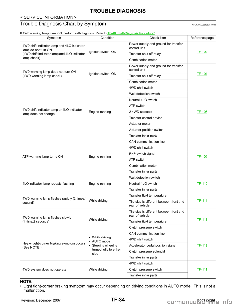
Trouble Diagnosis Chart by Symptom
INFOID:0000000003532525
If 4WD warning lamp turns ON, perform self-diagnosis. Refer to TF-48, "Self-Diagnosis Procedure" .
NOTE:
• Light tight-corner braking symptom may occur depending on driving conditions in AUTO mode. This is not a
malfunction.
Symptom Condition Check item Reference page
4WD shift indicator lamp and 4LO indicator
lamp do not turn ON
(4WD shift indicator lamp and 4LO indicator
lamp check)Ignition switch: ONPower supply and ground for transfer
control unit
TF-102
Transfer shut off relay
Combination meter
4WD warning lamp does not turn ON
(4WD warning lamp check)Ignition switch: ONPower supply and ground for transfer
control unit
TF-104
Transfer shut off relay
Combination meter
4WD shift indicator lamp or 4LO indicator
lamp does not changeEngine running4WD shift switch
TF-107
Wait detection switch
Neutral-4LO switch
ATP switch
2-4WD solenoid
Transfer control device
Actuator motor
Actuator position switch
Transfer inner parts
ATP warning lamp turns ON Engine runningCAN communication line
TF-109
4WD shift switch
PNP switch signal
ATP switch
Combination meter
Transfer inner parts
4LO indicator lamp repeats flashing Engine runningWait detection switch
TF-110
Neutral-4LO switch
Transfer inner parts
4WD warning lamp flashes rapidly (2 times/
second)While drivingTransfer fluid temperature
TF-111
Tire size is different between front and
rear of vehicle
4WD warning lamp flashes slowly
(1 time/2 seconds)While drivingTire size is different between front and
rear of vehicle.
TF-112
Transfer fluid temperature
Clutch pressure switch
Heavy tight-corner braking symptom occurs
(See NOTE.)• While driving
•AUTO mode
• Steering wheel is
turned fully to either
sideCAN communication line
TF-113
4WD shift switch
Accelerator pedal position signal
Clutch pressure solenoid
Transfer inner parts
4WD system does not operate While driving4WD shift switch
TF-114
Clutch pressure switch
Transfer inner parts