2007 INFINITI QX56 turn signal
[x] Cancel search: turn signalPage 2716 of 3061

SE-44
< SERVICE INFORMATION >
AUTOMATIC DRIVE POSITIONER
OK or NG
OK >> Replace door mirror LH. Refer to GW-84, "Door Mirror Assembly".
NG >> Repair or replace harness.
Mirror Motor RH Circuit InspectionINFOID:0000000003533179
1.CHECK DOOR MIRROR RH MECHANISM
Check the following items.
Operation malfunction caused by a foreign object caught in door mirror face edge.
OK or NG
OK >> GO TO 2.
NG >> Repair or replace the malfunctioning parts, and check the symptom again.
2.CHECK FUNCTION
With CONSULT-II
Check the operation with “MIRROR MOTOR RH” in the ACTIVE
TEST.
Without CONSULT-II
GO TO 3.
OK or NG
OK >> Mirror motor RH circuit is OK.
NG >> GO TO 3.
3.CHECK DOOR MIRROR RH CIRCUIT HARNESS CONTINUITY
1. Turn ignition switch OFF.
2. Disconnect automatic drive positioner control unit and door mir-
ror RH.
3. Check continuity between automatic drive positioner control unit
connector M33 terminals 14, 15, 30 and door mirror RH connec-
tor D107 terminals 1, 2, 3.
4. Check continuity between automatic drive positioner control unit
connector M33 terminal 14, 15, 30 and ground.
ConnectorTe r m i n a l s
ConditionVoltage (V)
(Approx.)
(+) (-)
D41
GroundWhen motor is
operated UP1.5 - Battery voltage
Other than above 0
2When motor is
operated LEFT1.5 - Battery voltage
Other than above 0
3 When motor is
operated DOWN or RIGHT1.5 - Battery voltage
Other than above 0
Test item Description
MIRROR MOTOR RHThe mirror motor RH moves the mirror UP/DOWN and
LEFT/RIGHT by receiving the drive signal.
PIIA0202E
14 - 1 : Continuity should exist.
15 - 2 : Continuity should exist.
30 - 3 : Continuity should exist.
LIIA1001E
Page 2717 of 3061
AUTOMATIC DRIVE POSITIONER
SE-45
< SERVICE INFORMATION >
C
D
E
F
G
H
J
K
L
MA
B
SE
N
O
P
OK or NG
OK >> GO TO 4.
NG >> Repair or replace harness.
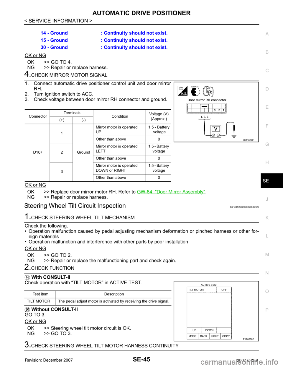
4.CHECK MIRROR MOTOR SIGNAL
1. Connect automatic drive positioner control unit and door mirror
RH.
2. Turn ignition switch to ACC.
3. Check voltage between door mirror RH connector and ground.
OK or NG
OK >> Replace door mirror motor RH. Refer to GW-84, "Door Mirror Assembly".
NG >> Repair or replace harness.
Steering Wheel Tilt Circuit InspectionINFOID:0000000003533180
1.CHECK STEERING WHEEL TILT MECHANISM
Check the following.
• Operation malfunction caused by pedal adjusting mechanism deformation or pinched harness or other for-
eign materials
• Operation malfunction and interference with other parts by poor installation
OK or NG
OK >> GO TO 2.
NG >> Repair or replace the malfunctioning part and check again.
2.CHECK FUNCTION
With CONSULT-II
Check operation with “TILT MOTOR” in ACTIVE TEST.
Without CONSULT-II
GO TO 3.
OK or NG
OK >> Steering wheel tilt motor circuit is OK.
NG >> GO TO 3.
3.CHECK STEERING WHEEL TILT MOTOR HARNESS CONTINUITY 14 - Ground : Continuity should not exist.
15 - Ground : Continuity should not exist.
30 - Ground : Continuity should not exist.
ConnectorTe r m i n a l s
ConditionVoltage (V)
(Approx.)
(+) (-)
D1071
GroundMirror motor is operated
UP1.5 - Battery
voltage
Other than above 0
2Mirror motor is operated
LEFT1.5 - Battery
voltage
Other than above 0
3Mirror motor is operated
DOWN or RIGHT1.5 - Battery
voltage
Other than above 0
LIIA1002E
Test item Description
TILT MOTOR The pedal adjust motor is activated by receiving the drive signal.
PIIA0280E
Page 2718 of 3061
SE-46
< SERVICE INFORMATION >
AUTOMATIC DRIVE POSITIONER
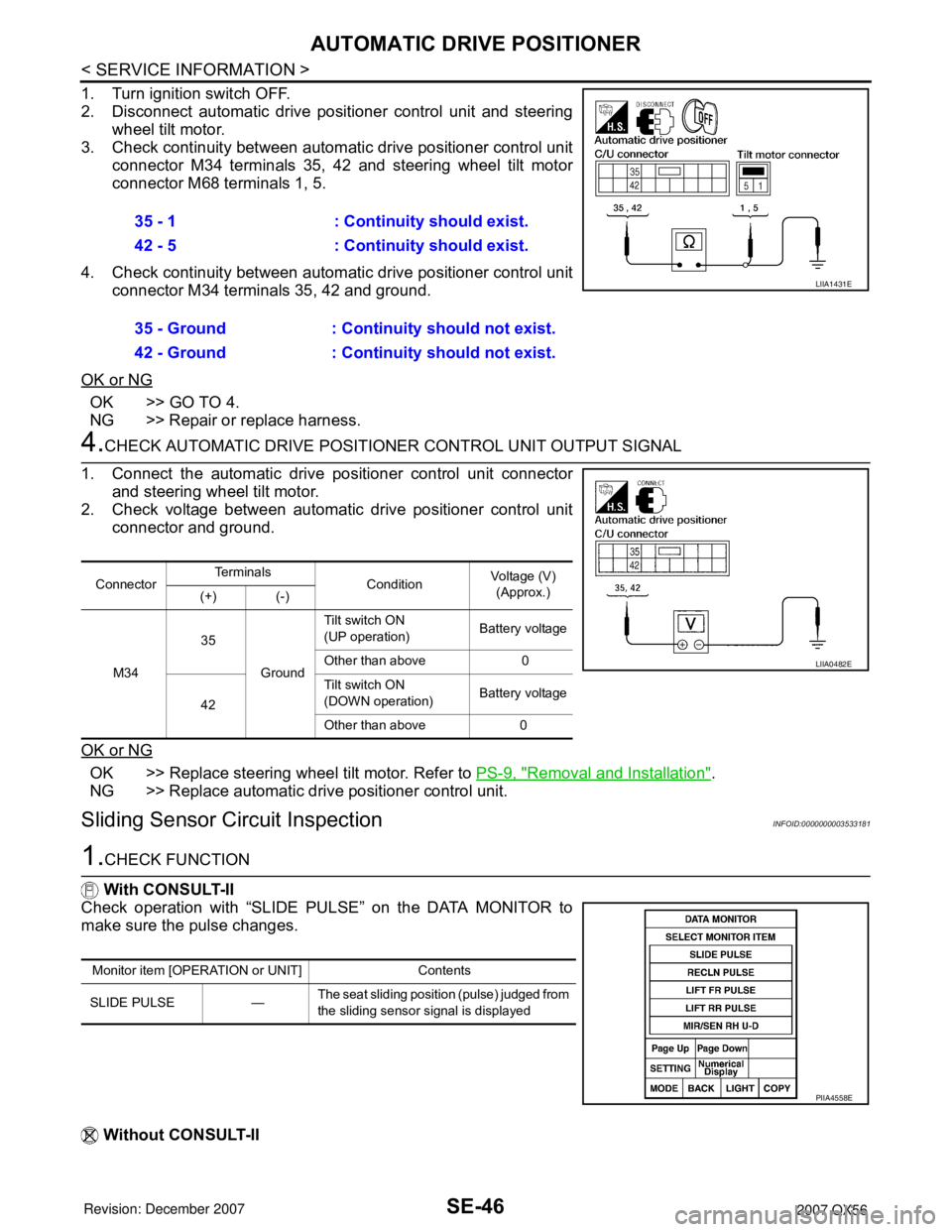
1. Turn ignition switch OFF.
2. Disconnect automatic drive positioner control unit and steering
wheel tilt motor.
3. Check continuity between automatic drive positioner control unit
connector M34 terminals 35, 42 and steering wheel tilt motor
connector M68 terminals 1, 5.
4. Check continuity between automatic drive positioner control unit
connector M34 terminals 35, 42 and ground.
OK or NG
OK >> GO TO 4.
NG >> Repair or replace harness.
4.CHECK AUTOMATIC DRIVE POSITIONER CONTROL UNIT OUTPUT SIGNAL
1. Connect the automatic drive positioner control unit connector
and steering wheel tilt motor.
2. Check voltage between automatic drive positioner control unit
connector and ground.
OK or NG
OK >> Replace steering wheel tilt motor. Refer to PS-9, "Removal and Installation".
NG >> Replace automatic drive positioner control unit.
Sliding Sensor Circuit InspectionINFOID:0000000003533181
1.CHECK FUNCTION
With CONSULT-II
Check operation with “SLIDE PULSE” on the DATA MONITOR to
make sure the pulse changes.
Without CONSULT-II35 - 1 : Continuity should exist.
42 - 5 : Continuity should exist.
35 - Ground : Continuity should not exist.
42 - Ground : Continuity should not exist.
LIIA1431E
ConnectorTe r m i n a l s
ConditionVoltage (V)
(Approx.)
(+) (-)
M3435
GroundTilt switch ON
(UP operation)Battery voltage
Other than above 0
42Tilt switch ON
(DOWN operation)Battery voltage
Other than above 0
LIIA0482E
Monitor item [OPERATION or UNIT] Contents
SLIDE PULSE —The seat sliding position (pulse) judged from
the sliding sensor signal is displayed
PIIA4558E
Page 2719 of 3061
AUTOMATIC DRIVE POSITIONER
SE-47
< SERVICE INFORMATION >
C
D
E
F
G
H
J
K
L
MA
B
SE
N
O
P
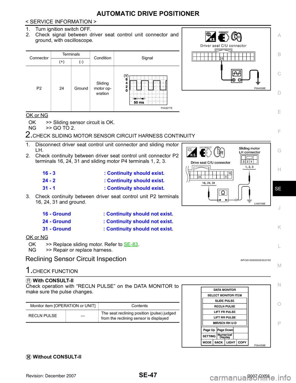
1. Turn ignition switch OFF.
2. Check signal between driver seat control unit connector and
ground, with oscilloscope.
OK or NG
OK >> Sliding sensor circuit is OK.
NG >> GO TO 2.
2.CHECK SLIDING MOTOR SENSOR CIRCUIT HARNESS CONTINUITY
1. Disconnect driver seat control unit connector and sliding motor
LH.
2. Check continuity between driver seat control unit connector P2
terminals 16, 24, 31 and sliding motor P4 terminals 1, 2, 3.
3. Check continuity between driver seat control unit P2 terminals
16, 24, 31 and ground.
OK or NG
OK >> Replace sliding motor. Refer to SE-83.
NG >> Repair or replace harness.
Reclining Sensor Circuit InspectionINFOID:0000000003533182
1.CHECK FUNCTION
With CONSULT-II
Check operation with “RECLN PULSE” on the DATA MONITOR to
make sure the pulse changes.
Without CONSULT-II
ConnectorTe r m i n a l s
Condition Signal
(+) (-)
P2 24 GroundSliding
motor op-
eration
PIIA4556E
PIIA3277E
16 - 3 : Continuity should exist.
24 - 2 : Continuity should exist.
31 - 1 : Continuity should exist.
16 - Ground : Continuity should not exist.
24 - Ground : Continuity should not exist.
31 - Ground : Continuity should not exist.
LIIA0706E
Monitor item [OPERATION or UNIT] Contents
RECLN PULSE —The seat reclining position (pulse) judged
from the reclining sensor is displayed
PIIA4558E
Page 2720 of 3061
SE-48
< SERVICE INFORMATION >
AUTOMATIC DRIVE POSITIONER
1. Turn ignition switch OFF.
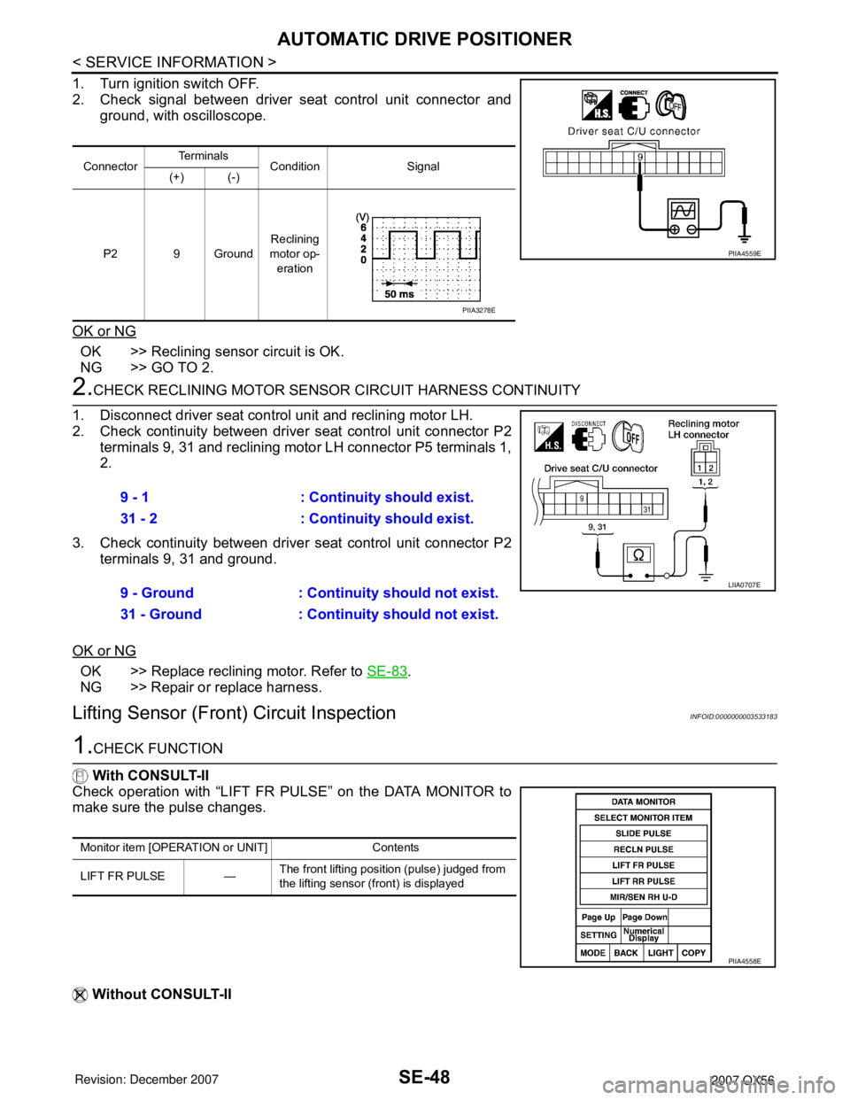
2. Check signal between driver seat control unit connector and
ground, with oscilloscope.
OK or NG
OK >> Reclining sensor circuit is OK.
NG >> GO TO 2.
2.CHECK RECLINING MOTOR SENSOR CIRCUIT HARNESS CONTINUITY
1. Disconnect driver seat control unit and reclining motor LH.
2. Check continuity between driver seat control unit connector P2
terminals 9, 31 and reclining motor LH connector P5 terminals 1,
2.
3. Check continuity between driver seat control unit connector P2
terminals 9, 31 and ground.
OK or NG
OK >> Replace reclining motor. Refer to SE-83.
NG >> Repair or replace harness.
Lifting Sensor (Front) Circuit InspectionINFOID:0000000003533183
1.CHECK FUNCTION
With CONSULT-II
Check operation with “LIFT FR PULSE” on the DATA MONITOR to
make sure the pulse changes.
Without CONSULT-II
ConnectorTe r m i n a l s
Condition Signal
(+) (-)
P2 9 GroundReclining
motor op-
eration
PIIA4559E
PIIA3278E
9 - 1 : Continuity should exist.
31 - 2 : Continuity should exist.
9 - Ground : Continuity should not exist.
31 - Ground : Continuity should not exist.
LIIA0707E
Monitor item [OPERATION or UNIT] Contents
LIFT FR PULSE —The front lifting position (pulse) judged from
the lifting sensor (front) is displayed
PIIA4558E
Page 2721 of 3061
AUTOMATIC DRIVE POSITIONER
SE-49
< SERVICE INFORMATION >
C
D
E
F
G
H
J
K
L
MA
B
SE
N
O
P
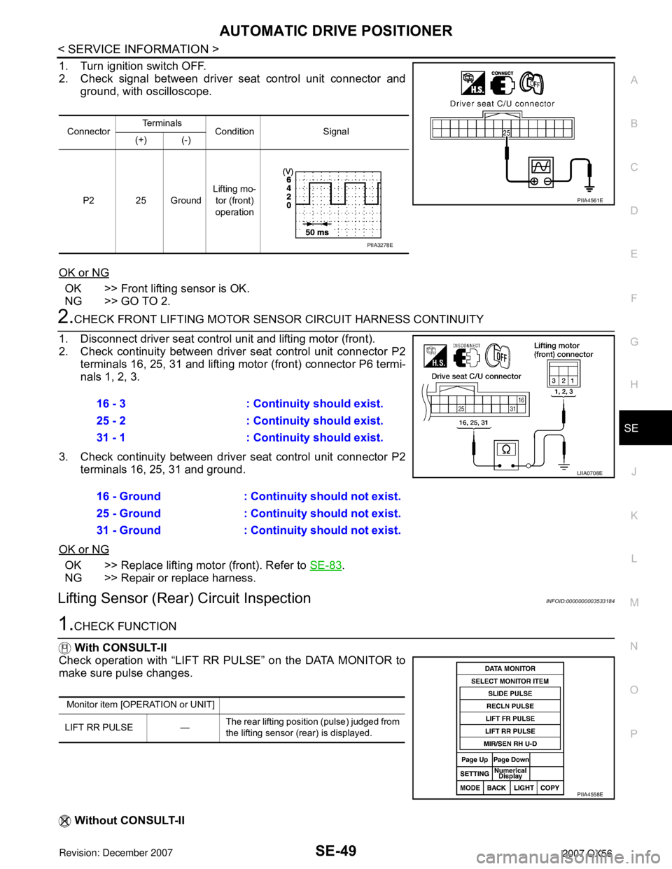
1. Turn ignition switch OFF.
2. Check signal between driver seat control unit connector and
ground, with oscilloscope.
OK or NG
OK >> Front lifting sensor is OK.
NG >> GO TO 2.
2.CHECK FRONT LIFTING MOTOR SENSOR CIRCUIT HARNESS CONTINUITY
1. Disconnect driver seat control unit and lifting motor (front).
2. Check continuity between driver seat control unit connector P2
terminals 16, 25, 31 and lifting motor (front) connector P6 termi-
nals 1, 2, 3.
3. Check continuity between driver seat control unit connector P2
terminals 16, 25, 31 and ground.
OK or NG
OK >> Replace lifting motor (front). Refer to SE-83.
NG >> Repair or replace harness.
Lifting Sensor (Rear) Circuit InspectionINFOID:0000000003533184
1.CHECK FUNCTION
With CONSULT-II
Check operation with “LIFT RR PULSE” on the DATA MONITOR to
make sure pulse changes.
Without CONSULT-II
ConnectorTe r m i n a l s
Condition Signal
(+) (-)
P2 25 GroundLifting mo-
tor (front)
operation
PIIA4561E
PIIA3278E
16 - 3 : Continuity should exist.
25 - 2 : Continuity should exist.
31 - 1 : Continuity should exist.
16 - Ground : Continuity should not exist.
25 - Ground : Continuity should not exist.
31 - Ground : Continuity should not exist.
LIIA0708E
Monitor item [OPERATION or UNIT]
LIFT RR PULSE —The rear lifting position (pulse) judged from
the lifting sensor (rear) is displayed.
PIIA4558E
Page 2722 of 3061
SE-50
< SERVICE INFORMATION >
AUTOMATIC DRIVE POSITIONER
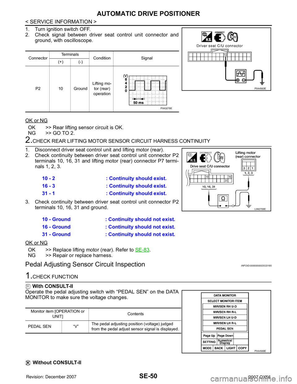
1. Turn ignition switch OFF.
2. Check signal between driver seat control unit connector and
ground, with oscilloscope.
OK or NG
OK >> Rear lifting sensor circuit is OK.
NG >> GO TO 2.
2.CHECK REAR LIFTING MOTOR SENSOR CIRCUIT HARNESS CONTINUITY
1. Disconnect driver seat control unit and lifting motor (rear).
2. Check continuity between driver seat control unit connector P2
terminals 10, 16, 31 and lifting motor (rear) connector P7 termi-
nals 1, 2, 3.
3. Check continuity between driver seat control unit connector P2
terminals 10, 16, 31 and ground.
OK or NG
OK >> Replace lifting motor (rear). Refer to SE-83.
NG >> Repair or replace harness.
Pedal Adjusting Sensor Circuit InspectionINFOID:0000000003533185
1.CHECK FUNCTION
With CONSULT-II
Operate the pedal adjusting switch with “PEDAL SEN” on the DATA
MONITOR to make sure the voltage changes.
Without CONSULT-II
ConnectorTe r m i n a l s
Condition Signal
(+) (-)
P2 10 GroundLifting mo-
tor (rear)
operation
PIIA4563E
PIIA3278E
10 - 2 : Continuity should exist.
16 - 3 : Continuity should exist.
31 - 1 : Continuity should exist.
10 - Ground : Continuity should not exist.
16 - Ground : Continuity should not exist.
31 - Ground : Continuity should not exist.
LIIA0709E
Monitor item [OPERATION or
UNIT]Contents
PEDAL SEN “V”The pedal adjusting position (voltage) judged
from the pedal adjust sensor signal is displayed.
PIIA4568E
Page 2727 of 3061
AUTOMATIC DRIVE POSITIONER
SE-55
< SERVICE INFORMATION >
C
D
E
F
G
H
J
K
L
MA
B
SE
N
O
P
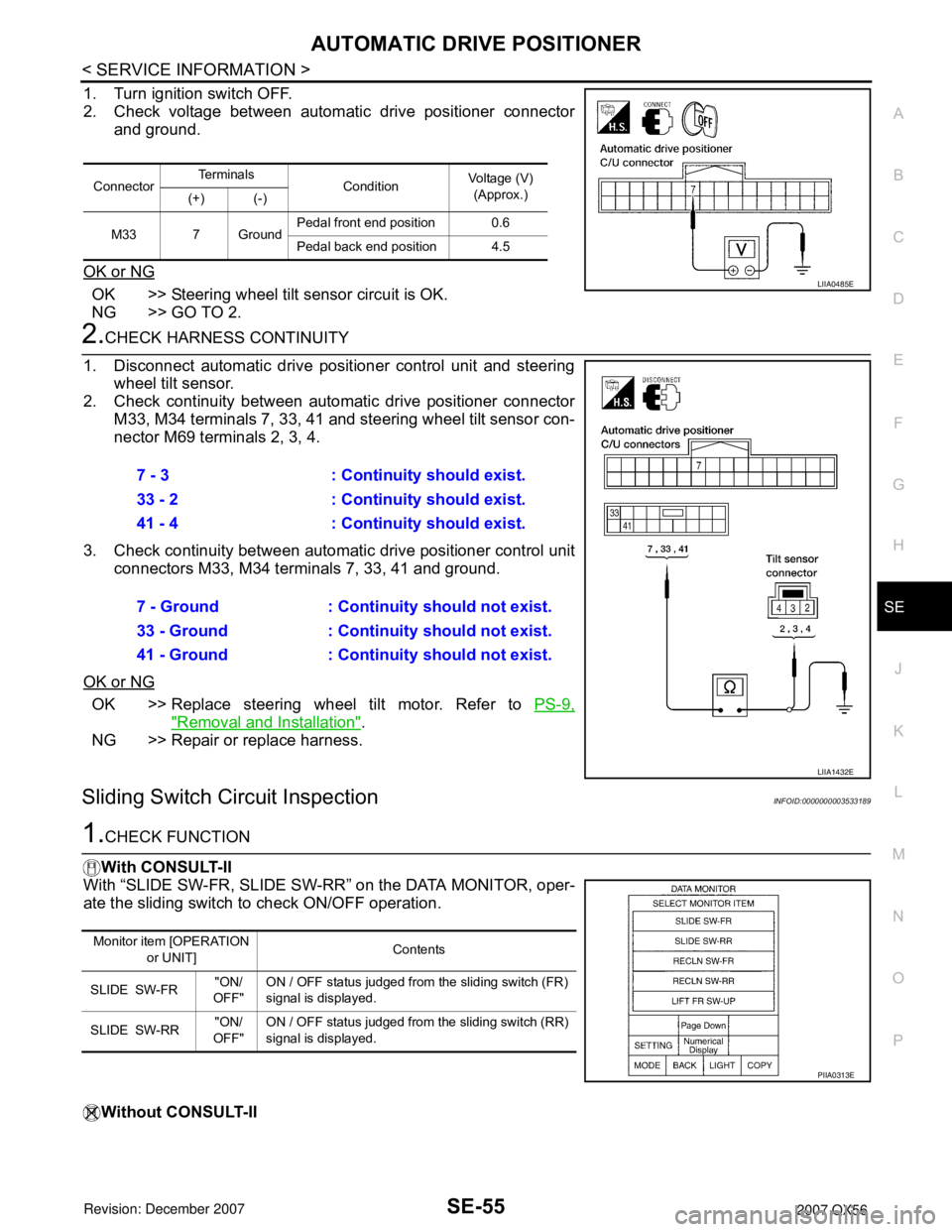
1. Turn ignition switch OFF.
2. Check voltage between automatic drive positioner connector
and ground.
OK or NG
OK >> Steering wheel tilt sensor circuit is OK.
NG >> GO TO 2.
2.CHECK HARNESS CONTINUITY
1. Disconnect automatic drive positioner control unit and steering
wheel tilt sensor.
2. Check continuity between automatic drive positioner connector
M33, M34 terminals 7, 33, 41 and steering wheel tilt sensor con-
nector M69 terminals 2, 3, 4.
3. Check continuity between automatic drive positioner control unit
connectors M33, M34 terminals 7, 33, 41 and ground.
OK or NG
OK >> Replace steering wheel tilt motor. Refer to PS-9,
"Removal and Installation".
NG >> Repair or replace harness.
Sliding Switch Circuit InspectionINFOID:0000000003533189
1.CHECK FUNCTION
With CONSULT-II
With “SLIDE SW-FR, SLIDE SW-RR” on the DATA MONITOR, oper-
ate the sliding switch to check ON/OFF operation.
Without CONSULT-II
ConnectorTe r m i n a l s
ConditionVoltage (V)
(Approx.)
(+) (-)
M33 7 GroundPedal front end position 0.6
Pedal back end position 4.5
LIIA0485E
7 - 3 : Continuity should exist.
33 - 2 : Continuity should exist.
41 - 4 : Continuity should exist.
7 - Ground : Continuity should not exist.
33 - Ground : Continuity should not exist.
41 - Ground : Continuity should not exist.
LIIA1432E
Monitor item [OPERATION
or UNIT]Contents
SLIDE SW-FR"ON/
OFF"ON / OFF status judged from the sliding switch (FR)
signal is displayed.
SLIDE SW-RR"ON/
OFF"ON / OFF status judged from the sliding switch (RR)
signal is displayed.
PIIA0313E