2007 INFINITI QX56 turn signal
[x] Cancel search: turn signalPage 2322 of 3061
INTERIOR ROOM LAMP
LT-115
< SERVICE INFORMATION >
C
D
E
F
G
H
I
J
L
MA
B
LT
N
O
P
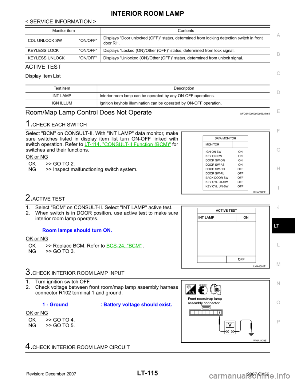
ACTIVE TEST
Display Item List
Room/Map Lamp Control Does Not OperateINFOID:0000000003533463
1.CHECK EACH SWITCH
Select "BCM" on CONSULT-II. With "INT LAMP" data monitor, make
sure switches listed in display item list turn ON-OFF linked with
switch operation. Refer to LT-114, "
CONSULT-II Function (BCM)" for
switches and their functions.
OK or NG
OK >> GO TO 2.
NG >> Inspect malfunctioning switch system.
2.ACTIVE TEST
1. Select "BCM" on CONSULT-II. Select "INT LAMP" active test.
2. When switch is in DOOR position, use active test to make sure
interior room lamp operates.
OK or NG
OK >> Replace BCM. Refer to BCS-24, "BCM" .
NG >> GO TO 3.
3.CHECK INTERIOR ROOM LAMP INPUT
1. Turn ignition switch OFF.
2. Check voltage between front room/map lamp assembly harness
connector R102 terminal 1 and ground.
OK or NG
OK >> GO TO 4.
NG >> GO TO 5.
4.CHECK INTERIOR ROOM LAMP CIRCUIT
CDL UNLOCK SW "ON/OFF"Displays "Door unlocked (OFF)" status, determined from locking detection switch in front
door RH.
KEYLESS LOCK "ON/OFF" Displays "Locked (ON)/Other (OFF)" status, determined from lock signal.
KEYLESS UNLOCK "ON/OFF" Displays "Unlocked (ON)/Other (OFF)" status, determined from unlock signal.Monitor item Contents
Test item Description
INT LAMP Interior room lamp can be operated by any ON-OFF operations.
IGN ILLUM Ignition keyhole illumination can be operated by ON-OFF operation.
SKIA5930E
Room lamps should turn ON.
LKIA0092E
1 - Ground : Battery voltage should exist.
WKIA1479E
Page 2345 of 3061

LT-138
< SERVICE INFORMATION >
BULB SPECIFICATIONS
BULB SPECIFICATIONS
HeadlampINFOID:0000000003533474
*: Always check with the Parts Department for the latest parts information.
Exterior LampINFOID:0000000003533475
*: Always check with the Parts Department for the latest parts information.
Interior Lamp/IlluminationINFOID:0000000003533476
*: Always check with the Parts Department for the latest parts information.Item Wattage (W)*
Low35 (D2R)
High60 (HB3)
Item Wattage (W)*
Front combination lampParking lamp (inner) 7
Parking lamp (outer) 7
Side marker lamp (front) 7
Rear combination lampStop/Tail lamp *
Side marker lamp (rear) *
Turn signal lamp 27
Back-up lamp*
Turn/fog lampFog 55 (H3)
Turn 21
License plate lamp5
High-mounted stop lamp*
Item Wattage (W)*
Glove box lamp3.4
Room/Map lamp8
Console box illumination lamp*
A/T device lamp2
Foot lamp3.4
Ste p lam p3.8
Cargo lamp7
Vanity lamp1.32
Personal lamp5
Puddle lamp8
Ignition keyhole illumination lamp0.74
Page 2366 of 3061
MA-4
< SERVICE INFORMATION >
GENERAL MAINTENANCE
GENERAL MAINTENANCE
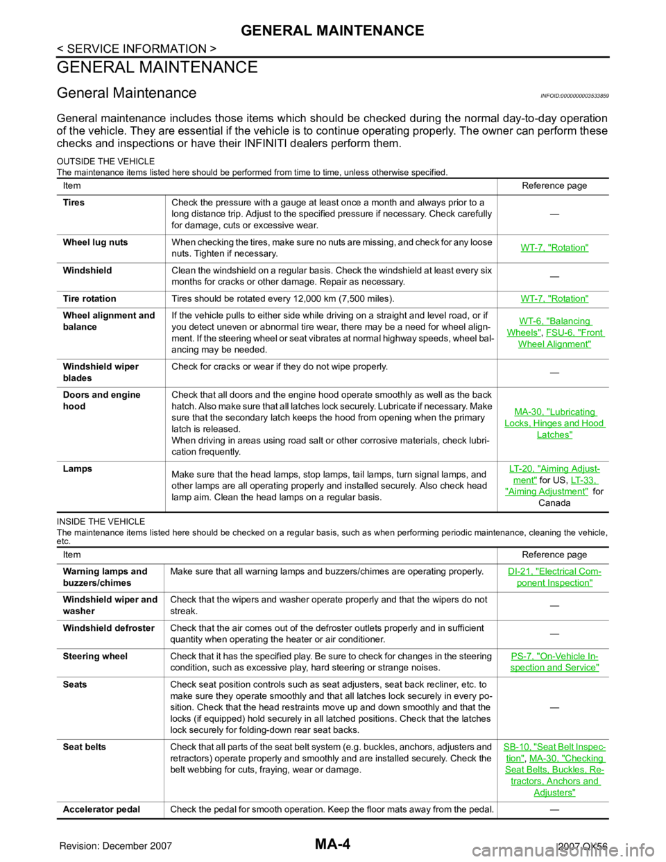
General MaintenanceINFOID:0000000003533859
General maintenance includes those items which should be checked during the normal day-to-day operation
of the vehicle. They are essential if the vehicle is to continue operating properly. The owner can perform these
checks and inspections or have their INFINITI dealers perform them.
OUTSIDE THE VEHICLE
The maintenance items listed here should be performed from time to time, unless otherwise specified.
INSIDE THE VEHICLE
The maintenance items listed here should be checked on a regular basis, such as when performing periodic maintenance, cleaning the vehicle,
etc.
ItemReference page
TiresCheck the pressure with a gauge at least once a month and always prior to a
long distance trip. Adjust to the specified pressure if necessary. Check carefully
for damage, cuts or excessive wear.—
Wheel lug nutsWhen checking the tires, make sure no nuts are missing, and check for any loose
nuts. Tighten if necessary.WT-7, "
Rotation"
WindshieldClean the windshield on a regular basis. Check the windshield at least every six
months for cracks or other damage. Repair as necessary.—
Tire rotationTires should be rotated every 12,000 km (7,500 miles).WT-7, "
Rotation"
Wheel alignment and
balanceIf the vehicle pulls to either side while driving on a straight and level road, or if
you detect uneven or abnormal tire wear, there may be a need for wheel align-
ment. If the steering wheel or seat vibrates at normal highway speeds, wheel bal-
ancing may be needed.WT-6, "Balancing
Wheels", FSU-6, "Front
Wheel Alignment"
Windshield wiper
bladesCheck for cracks or wear if they do not wipe properly.
—
Doors and engine
hoodCheck that all doors and the engine hood operate smoothly as well as the back
hatch. Also make sure that all latches lock securely. Lubricate if necessary. Make
sure that the secondary latch keeps the hood from opening when the primary
latch is released.
When driving in areas using road salt or other corrosive materials, check lubri-
cation frequently.MA-30, "
Lubricating
Locks, Hinges and Hood
Latches"
Lamps
Make sure that the head lamps, stop lamps, tail lamps, turn signal lamps, and
other lamps are all operating properly and installed securely. Also check head
lamp aim. Clean the head lamps on a regular basis.LT- 2 0 , "Aiming Adjust-
ment" for US, LT- 3 3 ,
"Aiming Adjustment" for
Canada
ItemReference page
Warning lamps and
buzzers/chimesMake sure that all warning lamps and buzzers/chimes are operating properly.DI-21, "
Electrical Com-
ponent Inspection"
Windshield wiper and
washerCheck that the wipers and washer operate properly and that the wipers do not
streak.—
Windshield defrosterCheck that the air comes out of the defroster outlets properly and in sufficient
quantity when operating the heater or air conditioner.—
Steering wheelCheck that it has the specified play. Be sure to check for changes in the steering
condition, such as excessive play, hard steering or strange noises.PS-7, "
On-Vehicle In-
spection and Service"
SeatsCheck seat position controls such as seat adjusters, seat back recliner, etc. to
make sure they operate smoothly and that all latches lock securely in every po-
sition. Check that the head restraints move up and down smoothly and that the
locks (if equipped) hold securely in all latched positions. Check that the latches
lock securely for folding-down rear seat backs.—
Seat beltsCheck that all parts of the seat belt system (e.g. buckles, anchors, adjusters and
retractors) operate properly and smoothly and are installed securely. Check the
belt webbing for cuts, fraying, wear or damage.SB-10, "
Seat Belt Inspec-
tion", MA-30, "Checking
Seat Belts, Buckles, Re-
tractors, Anchors and
Adjusters"
Accelerator pedalCheck the pedal for smooth operation. Keep the floor mats away from the pedal. —
Page 2419 of 3061
IPDM E/R (INTELLIGENT POWER DISTRIBUTION MODULE ENGINE ROOM)
PG-17
< SERVICE INFORMATION >
C
D
E
F
G
H
I
J
L
MA
B
PG
N
O
P
IPDM E/R (INTELLIGENT POWER DISTRIBUTION MODULE ENGINE
ROOM)
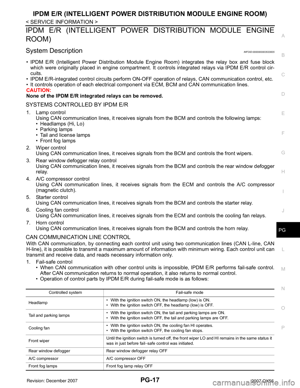
System DescriptionINFOID:0000000003533835
• IPDM E/R (Intelligent Power Distribution Module Engine Room) integrates the relay box and fuse block
which were originally placed in engine compartment. It controls integrated relays via IPDM E/R control cir-
cuits.
• IPDM E/R-integrated control circuits perform ON-OFF operation of relays, CAN communication control, etc.
• It controls operation of each electrical component via ECM, BCM and CAN communication lines.
CAUTION:
None of the IPDM E/R integrated relays can be removed.
SYSTEMS CONTROLLED BY IPDM E/R
1. Lamp control
Using CAN communication lines, it receives signals from the BCM and controls the following lamps:
• Headlamps (Hi, Lo)
• Parking lamps
• Tail and license lamps
• Front fog lamps
2. Wiper control
Using CAN communication lines, it receives signals from the BCM and controls the front wipers.
3. Rear window defogger relay control
Using CAN communication lines, it receives signals from the BCM and controls the rear window defogger
relay.
4. A/C compressor control
Using CAN communication lines, it receives signals from the ECM and controls the A/C compressor
(magnetic clutch).
5. Starter control
Using CAN communication lines, it receives signals from the BCM and controls the starter relay.
6. Cooling fan control
Using CAN communication lines, it receives signals from the ECM and controls the cooling fan relays.
7. Horn control
Using CAN communication lines, it receives signals from the BCM and controls the horn relay.
CAN COMMUNICATION LINE CONTROL
With CAN communication, by connecting each control unit using two communication lines (CAN L-line, CAN
H-line), it is possible to transmit a maximum amount of information with minimum wiring. Each control unit can
transmit and receive data, and reads necessary information only.
1. Fail-safe control
• When CAN communication with other control units is impossible, IPDM E/R performs fail-safe control.
After CAN communication returns to normal operation, it also returns to normal control.
• Operation of control parts by IPDM E/R during fail-safe mode is as follows:
Controlled system Fail-safe mode
Headlamp• With the ignition switch ON, the headlamp (low) is ON.
• With the ignition switch OFF, the headlamp (low) is OFF.
Tail and parking lamps• With the ignition switch ON, the tail and parking lamps are ON.
• With the ignition switch OFF, the tail and parking lamps are OFF.
Cooling fan• With the ignition switch ON, the cooling fan HI operates.
• With the ignition switch OFF, the cooling fan stops.
Front wiperUntil the ignition switch is turned off, the front wiper LO and HI remains in the same status it
was in just before fail−safe control was initiated.
Rear window defogger Rear window defogger relay OFF
A/C compressor A/C compressor OFF
Front fog lamps Front fog lamp relay OFF
Page 2420 of 3061
PG-18
< SERVICE INFORMATION >
IPDM E/R (INTELLIGENT POWER DISTRIBUTION MODULE ENGINE ROOM)
IPDM E/R STATUS CONTROL
In order to save power, IPDM E/R switches status automatically based on each operating condition.
1. CAN communication status
• CAN communication is normally performed with other control units.
• Individual unit control by IPDM E/R is normally performed.
• When sleep request signal is received from BCM, mode is switched to sleep waiting status.
2. Sleep waiting status
• Process to stop CAN communication is activated.
• All systems controlled by IPDM E/R are stopped. When 1 second has elapsed after CAN communica-
tion with other control units is stopped, mode switches to sleep status.
3. Sleep status
• IPDM E/R operates in low current-consumption mode.
• CAN communication is stopped.
• When a change in CAN communication signal is detected, mode switches to CAN communication sta-
tus.
• When a change in ignition switch signal is detected, mode switches to CAN communication status.
CAN Communication System DescriptionINFOID:0000000003533836
Refer to LAN-4.
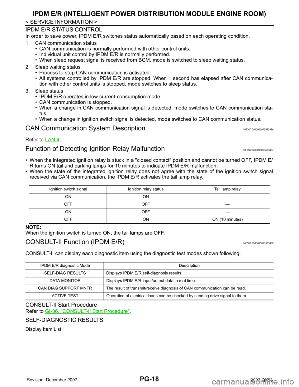
Function of Detecting Ignition Relay MalfunctionINFOID:0000000003533837
• When the integrated ignition relay is stuck in a "closed contact" position and cannot be turned OFF, IPDM E/
R turns ON tail and parking lamps for 10 minutes to indicate IPDM E/R malfunction.
• When the state of the integrated ignition relay does not agree with the state of the ignition switch signal
received via CAN communication, the IPDM E/R activates the tail lamp relay.
NOTE:
When the ignition switch is turned ON, the tail lamps are OFF.
CONSULT-II Function (IPDM E/R)INFOID:0000000003533838
CONSULT-II can display each diagnostic item using the diagnostic test modes shown following.
CONSULT-II Start Procedure
Refer to GI-36, "CONSULT-II Start Procedure".
SELF-DIAGNOSTIC RESULTS
Display Item List
Ignition switch signal Ignition relay status Tail lamp relay
ON ON —
OFF OFF —
ON OFF —
OFF ON ON (10 minutes)
IPDM E/R diagnostic Mode Description
SELF-DIAG RESULTS Displays IPDM E/R self-diagnosis results.
DATA MONITOR Displays IPDM E/R input/output data in real time.
CAN DIAG SUPPORT MNTR The result of transmit/receive diagnosis of CAN communication can be read.
ACTIVE TEST Operation of electrical loads can be checked by sending drive signal to them.
Page 2422 of 3061

PG-20
< SERVICE INFORMATION >
IPDM E/R (INTELLIGENT POWER DISTRIBUTION MODULE ENGINE ROOM)
NOTE:
• Perform monitoring of IPDM E/R data with the ignition switch ON. When the ignition switch is in ACC posi-
tion, display may not be correct.
• (*1) This item is displayed, but does not function.
CAN DIAG SUPPORT MNTR
Refer to LAN-4.
ACTIVE TEST
Auto Active TestINFOID:0000000003533839
DESCRIPTION
• In auto active test mode, operation inspection can be performed when IPDM E/R sends a drive signal to the
following systems:
- Rear window defogger
- Front wipers
- Tail and parking lamps
- Front fog lamps
- Headlamps (Hi, Lo)
- A/C compressor (magnet clutch)
- Cooling fan
OPERATION PROCEDURE
1. Close hood and front door RH, and lift wiper arms away from windshield (to prevent glass damage by
wiper operation).
NOTE:
When auto active test is performed with hood opened, sprinkle water on windshield beforehand.
2. Turn ignition switch OFF.
3. Turn ignition switch ON and, within 20 seconds, press front door switch LH 10 times. Then turn ignition
switch OFF.
4. Turn ignition switch ON within 10 seconds after ignition switch OFF.
5. When auto active test mode is actuated, horn chirps once.
6. After a series of operations is repeated three times, auto active test is completed.
NOTE:
When auto active test mode has to be cancelled halfway, turn ignition switch OFF.
Theft warning
horn requestTHFT HRN REQ ON/OFF X X Signal status input from BCM
Horn chirp HORN CHIRP ON/OFF X X Output status of IPDM E/R
Daytime running
lamp requestDTRL REQ ON/OFF X X Signal status input from BCM Item nameCONSULT-II
screen displayDisplay or unitMonitor item selection
Description
ALL
SIGNALSMAIN
SIGNALSSELECTION
FROM MENU
Test name CONSULT-II screen display Description
Rear defogger output REAR DEFOGGERWith a certain ON-OFF operation, the rear defogger relay can be oper-
ated.
Front wiper (HI, LO) output FRONT WIPERWith a certain operation (OFF, HI ON, LO ON), the front wiper relay (Lo,
Hi) can be operated.
Cooling fan output MOTOR FAN With a certain operation (1, 2, 3, 4), the cooling fan can be operated.
Lamp (HI, LO, TAIL, FOG)
outputEXTERNAL LAMPSWith a certain operation (OFF, HI ON, LO ON, TAIL ON, FOG ON), the
lamp relay (Low, High, Tail, Fog) can be operated.
Cornering lamp output CORNERING LAMP —
Horn output HORN With a certain ON-OFF operation, the horn relay can be operated.
Page 2463 of 3061

HARNESS
PG-61
< SERVICE INFORMATION >
C
D
E
F
G
H
I
J
L
MA
B
PG
N
O
P
ICC/BS EC ICC Steering Switch
ICC/SW EC ICC Brake Switch
I/MIRR GW Inside Mirror (Auto Anti-Dazzling Mirror)
IATS EC Intake Air Temperature Sensor
IGNSYS EC Ignition System
ILL LT Illumination
INJECT EC Injector
INT/L LT Room/Map, Vanity, Cargo, Personal, Foot, Step, and Puddle Lamps
KEYLES BL Remote Keyless Entry System
KS EC Knock Sensor
MAFS EC Mass Air Flow Sensor
MAIN EC Main Power Supply and Ground Circuit
METER DI Speedometer, Tachometer, Temp. and Fuel Gauges
MIL/DL EC Malfunction Indicator Lamp
MIRROR GW Door Mirror
NATS BL Nissan Anti-Theft System
NAVI AV Navigation System
O2H2B1 EC Rear Heated Oxygen Sensor 2 Heater Bank 1
O2H2B2 EC Rear Heated Oxygen Sensor 2 Heater Bank 2
O2S2B1 EC Heated Oxygen Sensor 2 Bank 1
O2S2B2 EC Heated Oxygen Sensor 2 Bank 2
P/SCKT WW Power Socket
PGC/V EC EVAP Canister Purge Volume Control Solenoid Valve
PHASE EC Camshaft Position Sensor (PHASE) (Bank 1)
PNP/SW EC Park/Neutral Position Switch
POS EC Crankshaft Position Sensor (POS)
POWER PG Power Supply Routing
PRE/SE EC EVAP Control System Pressure Sensor
PS/SEN EC Power Steering Pressure Sensor
R/VIEW DI Rear View Monitor
RP/SEN EC Refrigerant Pressure Sensor
SEN/PW EC Sensor Power Supply
SHIFT AT A/T Shift Lock System
SONAR DI Rear Sonar System
SROOF RF Sunroof
SRS SRS Supplemental Restraint System
START SC Starting System
STOP/L LT Stop Lamp
T/TOW LT Trailer Tow
T/WARN WT Low Tire Pressure Warning System
TAIL/L LT Parking, License and Tail Lamps
T/F TF Transfer Case
TPS1 EC Throttle Position Sensor
TPS2 EC Throttle Position Sensor
TPS3 EC Throttle Position Sensor
TRNSCV BL HOMELINK® Universal Transceiver
TURN LT Turn Signal and Hazard Warning Lamps
VDC BRC Vehicle Dynamic Control System
VEHSEC BL Vehicle security (theft warning) system
VENT/V EC EVAP Canister Vent Control Valve
W/ANT AV Audio Antenna
WARN DI Warning Lamps
Page 2543 of 3061
SUNROOF
RF-11
< SERVICE INFORMATION >
C
D
E
F
G
H
J
K
L
MA
B
RF
N
O
P
• through sunroof switch terminal 4
• through sunroof switch terminal 2
• through sunroof motor assembly terminal 8
• through grounds M57, M61 and M79.
Then, the sunroof will tilt up.
TILT DOWN OPERATION
When the tilt switch is operated for tilt down, ground is supplied
• to sunroof motor assembly terminal 10
• through sunroof switch terminal 6
• through sunroof switch terminal 2
• through sunroof motor assembly terminal 8
• through grounds M57, M61 and M79.
Then, the sunroof will tilt down.
SLIDE OPEN OPERATION
When the switch is operated for slide open, ground is supplied
• to sunroof motor assembly terminal 9
• through sunroof switch terminal 3
• through sunroof switch terminal 2
• through sunroof motor assembly terminal 8
• through grounds M57, M61 and M79.
Then, the sunroof will slide open.
SLIDE CLOSE OPERATION
When the switch is operated for slide close, ground is supplied
• to sunroof motor assembly terminal 3
• through sunroof switch terminal 1
• through sunroof switch terminal 2
• through sunroof motor assembly terminal 8
• through grounds M57, M61 and M79.
Then, the sunroof will slide closed.
RETAINED POWER OPERATION
When the ignition switch is turned to OFF position from ON or START position, power is supplied for 45 sec-
onds.
The retained power operation is canceled when the driver or passenger side door is opened.
RAP signal period can be changed by CONSULT-II. Refer to RF-14, "
CONSULT-II Function (BCM)".
MEMORY RESET PROCEDURE
To reset the sunroof motor memory from any sunroof position (full open, partially open, closed, partially
vented, and vented), push and hold the sunroof tilt switch in the forward (DOWN) position until the sunroof is
fully closed. After it has closed all the way, push and hold the tilt switch forward (DOWN) for more than 2 sec-
onds to re-establish the motor preset position. The sunroof should now operate normally.
INTERRUPTION DETECTION FUNCTION
The CPU (central processing unit) monitors the sunroof motor operation and the sunroof position (fully-closed
or other) by the signals from the sunroof motor.
When sunroof motor detects an interruption during the following sliding close operations, sunroof switch con-
trols the motor for open and the sunroof will operate until it reaches full open position.
• automatic close operation when ignition switch is in the ON position.
• automatic close operation during retained power operation.
CAN Communication System DescriptionINFOID:0000000003533097
Refer to LAN-4.