2007 INFINITI QX56 battery
[x] Cancel search: batteryPage 2636 of 3061
SB-2
< SERVICE INFORMATION >
PRECAUTIONS
SERVICE INFORMATION
PRECAUTIONS
Precaution for Supplemental Restraint System (SRS) "AIR BAG" and "SEAT BELT
PRE-TENSIONER"
INFOID:0000000003532841
The Supplemental Restraint System such as “AIR BAG” and “SEAT BELT PRE-TENSIONER”, used along
with a front seat belt, helps to reduce the risk or severity of injury to the driver and front passenger for certain
types of collision. This system includes seat belt switch inputs and dual stage front air bag modules. The SRS
system uses the seat belt switches to determine the front air bag deployment, and may only deploy one front
air bag, depending on the severity of a collision and whether the front occupants are belted or unbelted.
Information necessary to service the system safely is included in the SRS and SB section of this Service Man-
ual.
WARNING:
• To avoid rendering the SRS inoperative, which could increase the risk of personal injury or death in
the event of a collision which would result in air bag inflation, all maintenance must be performed by
an authorized NISSAN/INFINITI dealer.
• Improper maintenance, including incorrect removal and installation of the SRS, can lead to personal
injury caused by unintentional activation of the system. For removal of Spiral Cable and Air Bag
Module, see the SRS section.
• Do not use electrical test equipment on any circuit related to the SRS unless instructed to in this
Service Manual. SRS wiring harnesses can be identified by yellow and/or orange harnesses or har-
ness connectors.
Precaution for Seat Belt ServiceINFOID:0000000003532842
CAUTION:
• Before removing the seat belt pre-tensioner assembly, turn the ignition switch OFF, disconnect both
battery cables and wait at least 3 minutes.
• After replacing or reinstalling seat belt pre-tensioner assembly, or reconnecting seat belt pre-ten-
sioner assembly connector, make sure entire SRS operates properly. Refer to SRS-20, "
SRS Opera-
tion Check".
• Do not disassemble buckle or seat belt assembly.
• Do not reuse seat belt anchor bolts after removal. Replace with new ones.
• Replace anchor bolts if they are deformed or worn out.
• Never oil tongue and buckle.
• If any component of seat belt assembly is questionable, do not repair. Replace the whole seat belt
assembly.
• If webbing is cut, frayed, or damaged, replace seat belt assembly.
• When replacing seat belt assembly, use a genuine NISSAN seat belt assembly.
AFTER A COLLISION
WARNING:
• Inspect all seat belt assemblies including retractors and attaching hardware after any collision.
• NISSAN recommends that all seat belt assemblies in use during a collision be replaced unless the
collision was minor and the belts show no damage and continue to operate properly. Failure to do so
could result in serious personal injury in an accident. Seat belt assemblies not in use during a colli-
sion should also be replaced if either damage or improper operation is noted. Seat belt pre-tensioner
should be replaced even if the seat belts are not in use during a frontal collision in which the air bags
are deployed.
Replace any seat belt assembly (including anchor bolts) if:
• The seat belt was in use at the time of a collision (except for minor collisions and the belts, retractors and
buckles show no damage and continue to operate properly).
• The seat belt was damaged in an accident. (i.e., torn webbing, bent retractor or guide, etc.)
• The seat belt attaching point was damaged in an accident. Inspect the seat belt attaching area for damage
or distortion and repair as necessary before installing a new seat belt assembly.
• Anchor bolts are deformed or worn out.
• The seat belt pre-tensioner should be replaced even if the seat belts are not in use during the collision in
which the air bags are deployed.
Page 2637 of 3061
SEAT BELTS
SB-3
< SERVICE INFORMATION >
C
D
E
F
G
I
J
K
L
MA
B
SB
N
O
P
SEAT BELTS
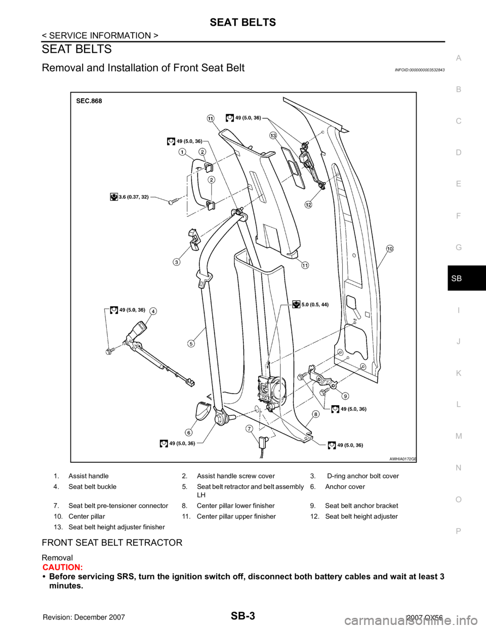
Removal and Installation of Front Seat BeltINFOID:0000000003532843
FRONT SEAT BELT RETRACTOR
Removal
CAUTION:
• Before servicing SRS, turn the ignition switch off, disconnect both battery cables and wait at least 3
minutes.
1. Assist handle 2. Assist handle screw cover 3. D-ring anchor bolt cover
4. Seat belt buckle 5. Seat belt retractor and belt assembly
LH6. Anchor cover
7. Seat belt pre-tensioner connector 8. Center pillar lower finisher 9. Seat belt anchor bracket
10. Center pillar 11. Center pillar upper finisher 12. Seat belt height adjuster
13. Seat belt height adjuster finisher
AWHIA0172GB
Page 2638 of 3061
SB-4
< SERVICE INFORMATION >
SEAT BELTS
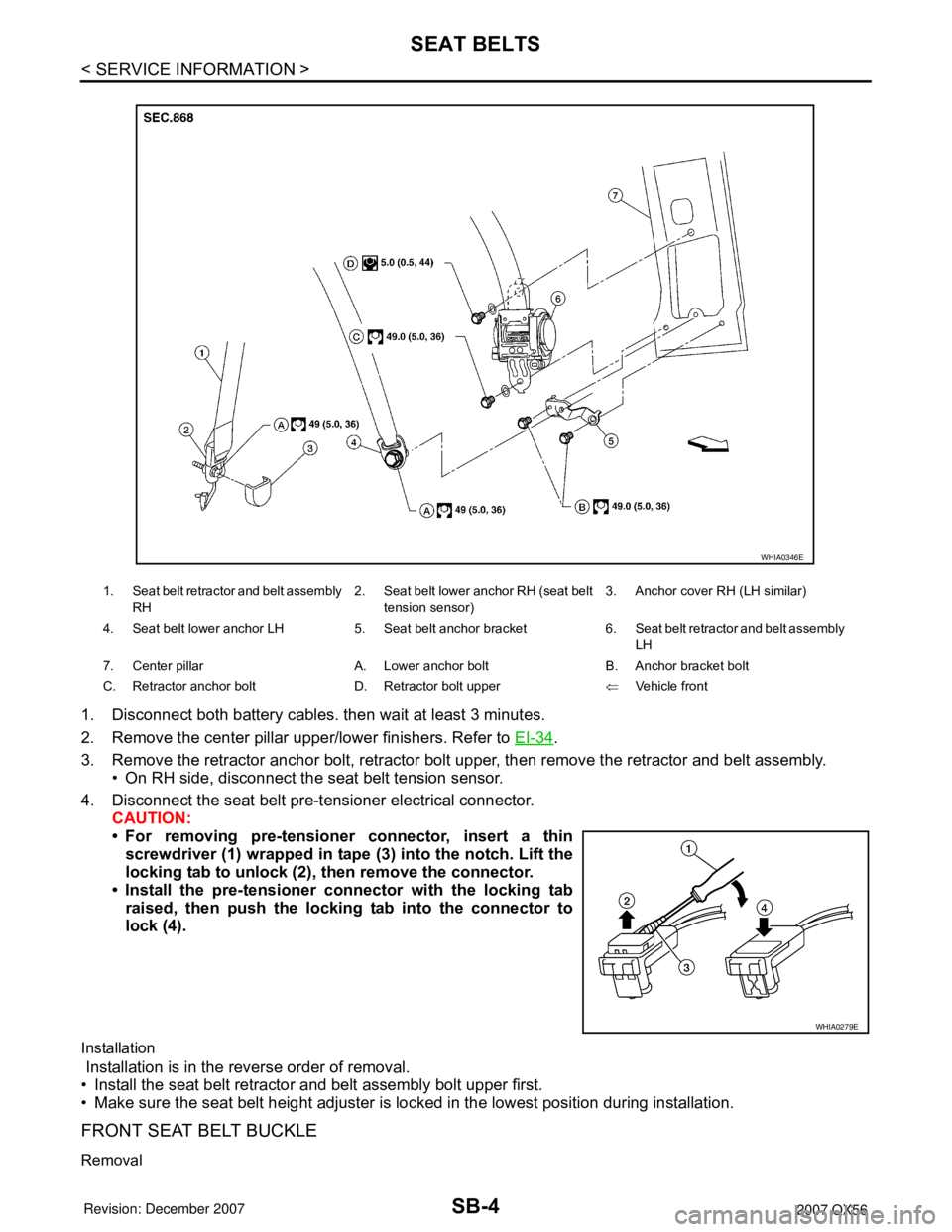
1. Disconnect both battery cables. then wait at least 3 minutes.
2. Remove the center pillar upper/lower finishers. Refer to EI-34
.
3. Remove the retractor anchor bolt, retractor bolt upper, then remove the retractor and belt assembly.
• On RH side, disconnect the seat belt tension sensor.
4. Disconnect the seat belt pre-tensioner electrical connector.
CAUTION:
• For removing pre-tensioner connector, insert a thin
screwdriver (1) wrapped in tape (3) into the notch. Lift the
locking tab to unlock (2), then remove the connector.
• Install the pre-tensioner connector with the locking tab
raised, then push the locking tab into the connector to
lock (4).
Installation
Installation is in the reverse order of removal.
• Install the seat belt retractor and belt assembly bolt upper first.
• Make sure the seat belt height adjuster is locked in the lowest position during installation.
FRONT SEAT BELT BUCKLE
Removal
1. Seat belt retractor and belt assembly
RH2. Seat belt lower anchor RH (seat belt
tension sensor)3. Anchor cover RH (LH similar)
4. Seat belt lower anchor LH 5. Seat belt anchor bracket 6. Seat belt retractor and belt assembly
LH
7. Center pillar A. Lower anchor bolt B. Anchor bracket bolt
C. Retractor anchor bolt D. Retractor bolt upper⇐Vehicle front
WHIA0346E
WHIA0279E
Page 2639 of 3061
SEAT BELTS
SB-5
< SERVICE INFORMATION >
C
D
E
F
G
I
J
K
L
MA
B
SB
N
O
P
1. Disconnect both battery cables, then wait at least 3 minutes.
2. Remove the front seat. Refer to SE-83
.
3. Remove the seat cushion. Refer to SE-85, "
Disassembly and Assembly".
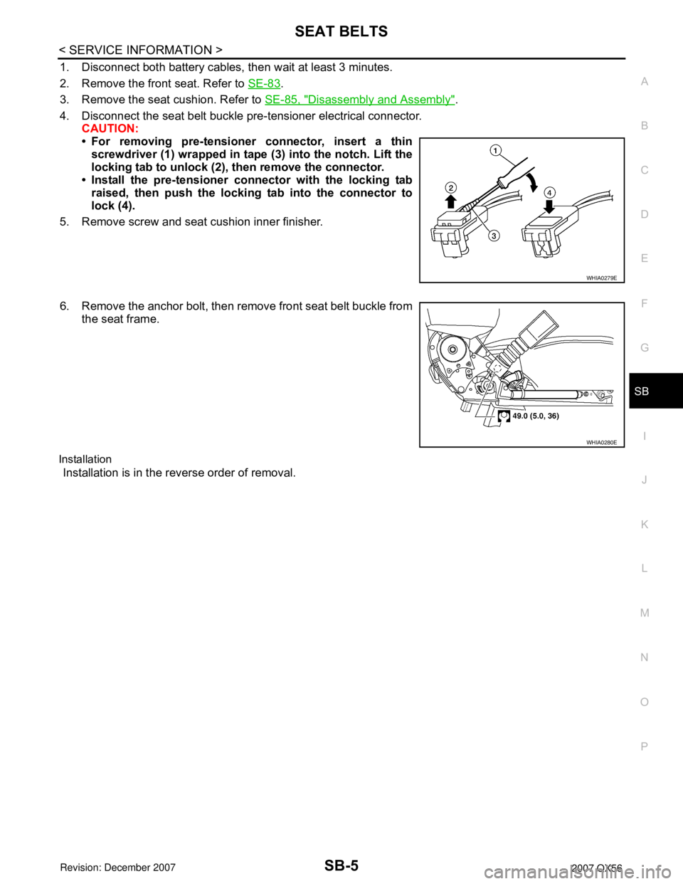
4. Disconnect the seat belt buckle pre-tensioner electrical connector.
CAUTION:
• For removing pre-tensioner connector, insert a thin
screwdriver (1) wrapped in tape (3) into the notch. Lift the
locking tab to unlock (2), then remove the connector.
• Install the pre-tensioner connector with the locking tab
raised, then push the locking tab into the connector to
lock (4).
5. Remove screw and seat cushion inner finisher.
6. Remove the anchor bolt, then remove front seat belt buckle from
the seat frame.
Installation
Installation is in the reverse order of removal.
WHIA0279E
WHIA0280E
Page 2649 of 3061

SC-1
ELECTRICAL
C
D
E
F
G
H
I
J
L
M
SECTION SC
A
B
SC
N
O
P
CONTENTS
STARTING & CHARGING SYSTEM
SERVICE INFORMATION ............................2
PRECAUTIONS ...................................................2
Precaution for Supplemental Restraint System
(SRS) "AIR BAG" and "SEAT BELT PRE-TEN-
SIONER" ...................................................................
2
Precaution for Power Generation Variable Voltage
Control System ..........................................................
2
PREPARATION ...................................................3
Special Service Tool .................................................3
Commercial Service Tool ..........................................3
BATTERY ............................................................4
How to Handle Battery ..............................................4
Trouble Diagnosis with Battery/Starting/Charging
System Tester ...........................................................
6
Removal and Installation ...........................................8
STARTING SYSTEM ..........................................9
System Description ...................................................9
Wiring Diagram - START - .......................................10
Trouble Diagnosis with Battery/Starting/Charging
System Tester .........................................................
10
Removal and Installation .........................................14
CHARGING SYSTEM .......................................15
System Description ..................................................15
Wiring Diagram - CHARGE - ...................................17
Trouble Diagnosis with Battery/Starting/Charging
System Tester .........................................................
17
Removal and Installation .........................................22
SERVICE DATA AND SPECIFICATIONS
(SDS) .................................................................
24
Battery .....................................................................24
Starter ......................................................................24
Generator ................................................................24
Page 2650 of 3061
SC-2
< SERVICE INFORMATION >
PRECAUTIONS
SERVICE INFORMATION
PRECAUTIONS
Precaution for Supplemental Restraint System (SRS) "AIR BAG" and "SEAT BELT
PRE-TENSIONER"
INFOID:0000000003533312
The Supplemental Restraint System such as “AIR BAG” and “SEAT BELT PRE-TENSIONER”, used along
with a front seat belt, helps to reduce the risk or severity of injury to the driver and front passenger for certain
types of collision. This system includes seat belt switch inputs and dual stage front air bag modules. The SRS
system uses the seat belt switches to determine the front air bag deployment, and may only deploy one front
air bag, depending on the severity of a collision and whether the front occupants are belted or unbelted.
Information necessary to service the system safely is included in the SRS and SB section of this Service Man-
ual.
WARNING:
• To avoid rendering the SRS inoperative, which could increase the risk of personal injury or death in
the event of a collision which would result in air bag inflation, all maintenance must be performed by
an authorized NISSAN/INFINITI dealer.
• Improper maintenance, including incorrect removal and installation of the SRS, can lead to personal
injury caused by unintentional activation of the system. For removal of Spiral Cable and Air Bag
Module, see the SRS section.
• Do not use electrical test equipment on any circuit related to the SRS unless instructed to in this
Service Manual. SRS wiring harnesses can be identified by yellow and/or orange harnesses or har-
ness connectors.
Precaution for Power Generation Variable Voltage Control SystemINFOID:0000000003533313
CAUTION:
For this model, the battery current sensor that is installed to the negative battery cable measures the
charging/discharging current of the battery and performs various engine controls. If an electrical com-
ponent is connected directly to the negative battery terminal, the current flowing through that compo-
nent will not be measured by the battery current sensor. This condition may cause a malfunction of
the engine control system and battery discharge may occur. Do not connect an electrical component
or ground wire directly to the battery terminal.
Page 2651 of 3061
PREPARATION
SC-3
< SERVICE INFORMATION >
C
D
E
F
G
H
I
J
L
MA
B
SC
N
O
P
PREPARATION
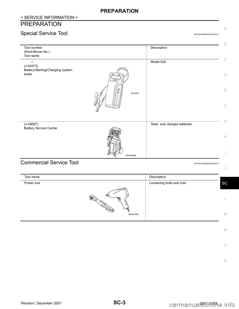
Special Service ToolINFOID:0000000003533314
Commercial Service ToolINFOID:0000000003533315
Tool number
(Kent-Moore No.)
Tool nameDescription
—
(J-44373)
Battery/Starting/Charging system
testerModel 620
(J-48087)
Battery Service CenterTests and charges batteries
SEL403X
WKIA5280E
Tool nameDescription
Power toolLoosening bolts and nuts
PBIC0190E
Page 2652 of 3061
SC-4
< SERVICE INFORMATION >
BATTERY
BATTERY
How to Handle BatteryINFOID:0000000003533316
CAUTION:
• If it becomes necessary to start the engine with a booster battery and jumper cables, use a 12-volt
booster battery.
• After connecting battery cables, ensure that they are tightly clamped to battery terminals for good
contact.
• Never add distilled water through the hole used to check specific gravity.
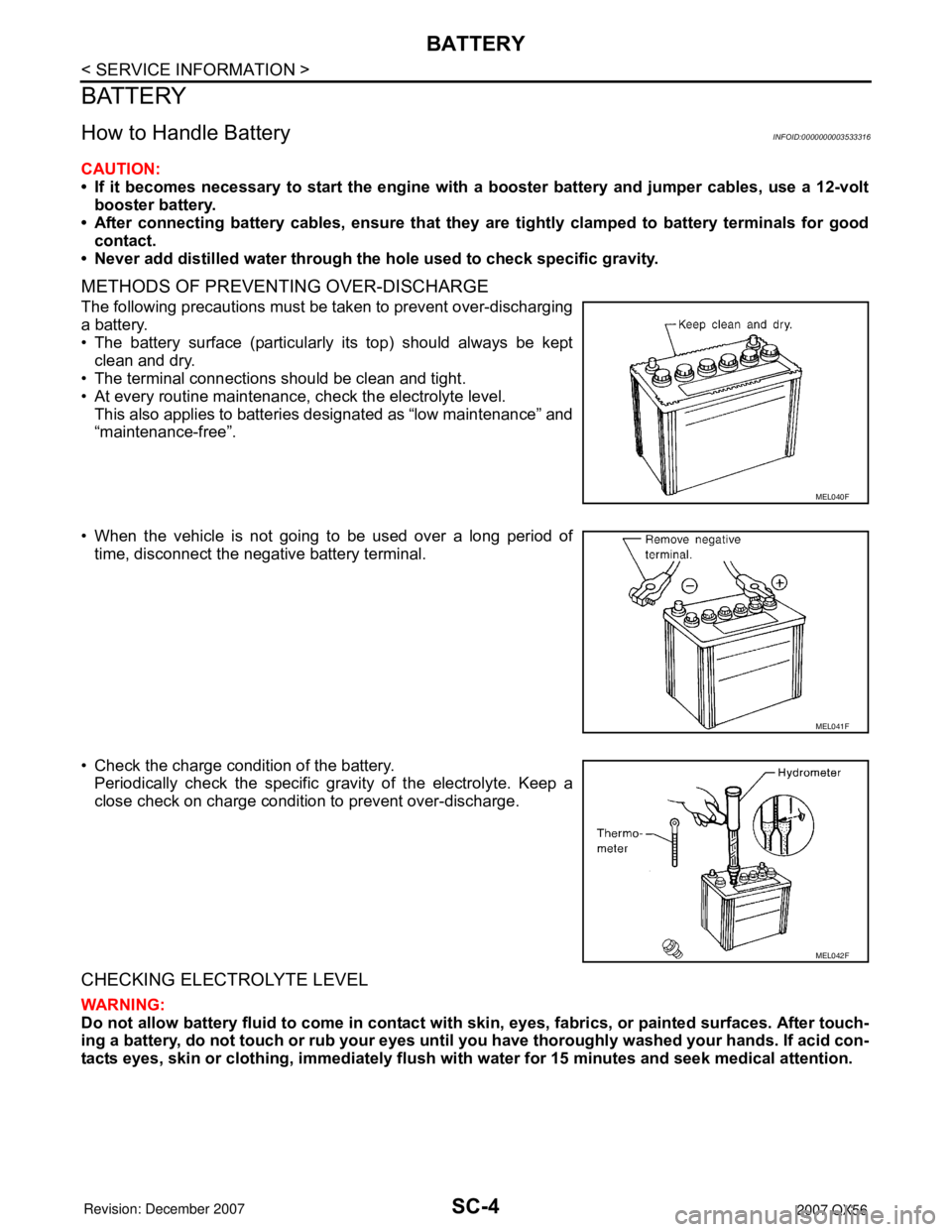
METHODS OF PREVENTING OVER-DISCHARGE
The following precautions must be taken to prevent over-discharging
a battery.
• The battery surface (particularly its top) should always be kept
clean and dry.
• The terminal connections should be clean and tight.
• At every routine maintenance, check the electrolyte level.
This also applies to batteries designated as “low maintenance” and
“maintenance-free”.
• When the vehicle is not going to be used over a long period of
time, disconnect the negative battery terminal.
• Check the charge condition of the battery.
Periodically check the specific gravity of the electrolyte. Keep a
close check on charge condition to prevent over-discharge.
CHECKING ELECTROLYTE LEVEL
WARNING:
Do not allow battery fluid to come in contact with skin, eyes, fabrics, or painted surfaces. After touch-
ing a battery, do not touch or rub your eyes until you have thoroughly washed your hands. If acid con-
tacts eyes, skin or clothing, immediately flush with water for 15 minutes and seek medical attention.
MEL040F
MEL041F
MEL042F