2007 INFINITI QX56 battery
[x] Cancel search: batteryPage 2257 of 3061

LT-50
< SERVICE INFORMATION >
FRONT FOG LAMP
With the fog lamp switch in the ON position, the CPU of the IPDM E/R grounds the coil side of the fog lamp
relay. The fog lamp relay then directs power
• through 20A fuse (No. 56, located in the IPDM E/R)
• through IPDM E/R terminal 50
• to front turn/fog lamp LH terminal 1, and
• through IPDM E/R terminal 51
• to front turn/fog lamp RH terminal 1.
Ground is supplied
• to front turn/fog lamp LH and RH terminal 3
• through grounds E9, E15 and E24.
With power and ground supplied, the front fog lamps illuminate.
COMBINATION SWITCH READING FUNCTION
Refer to BCS-3, "System Description" .
EXTERIOR LAMP BATTERY SAVER CONTROL
When the combination switch (lighting switch) is in the 2ND position (ON), the fog lamp switch is ON, and the
ignition switch is turned from ON or ACC to OFF, the battery saver control feature is activated.
Under this condition, the fog lamps (and headlamps) remain illuminated for 5 minutes, then the fog lamps (and
headlamps) are turned off.
Exterior lamp battery saver control mode can be changed by the function setting of CONSULT-II.
CAN Communication System DescriptionINFOID:0000000003533390
Refer to LAN-4, "CAN Communication System" .
Page 2261 of 3061

LT-54
< SERVICE INFORMATION >
FRONT FOG LAMP
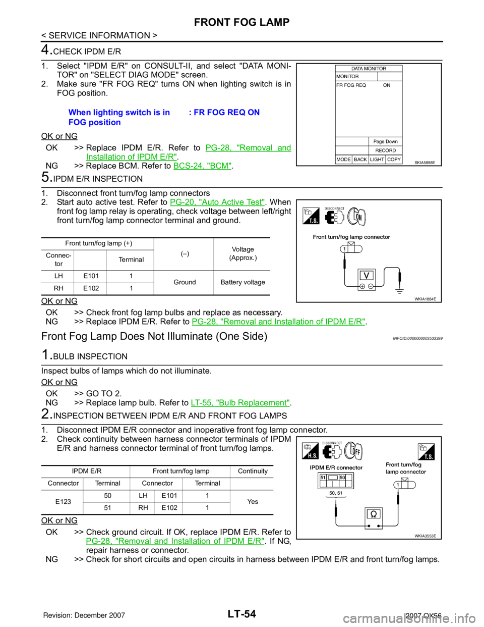
4.CHECK IPDM E/R
1. Select "IPDM E/R" on CONSULT-II, and select "DATA MONI-
TOR" on "SELECT DIAG MODE" screen.
2. Make sure "FR FOG REQ" turns ON when lighting switch is in
FOG position.
OK or NG
OK >> Replace IPDM E/R. Refer to PG-28, "Removal and
Installation of IPDM E/R".
NG >> Replace BCM. Refer to BCS-24, "
BCM".
5.IPDM E/R INSPECTION
1. Disconnect front turn/fog lamp connectors
2. Start auto active test. Refer to PG-20, "
Auto Active Test". When
front fog lamp relay is operating, check voltage between left/right
front turn/fog lamp connector terminal and ground.
OK or NG
OK >> Check front fog lamp bulbs and replace as necessary.
NG >> Replace IPDM E/R. Refer to PG-28, "
Removal and Installation of IPDM E/R".
Front Fog Lamp Does Not Illuminate (One Side)INFOID:0000000003533399
1.BULB INSPECTION
Inspect bulbs of lamps which do not illuminate.
OK or NG
OK >> GO TO 2.
NG >> Replace lamp bulb. Refer to LT-55, "
Bulb Replacement".
2.INSPECTION BETWEEN IPDM E/R AND FRONT FOG LAMPS
1. Disconnect IPDM E/R connector and inoperative front fog lamp connector.
2. Check continuity between harness connector terminals of IPDM
E/R and harness connector terminal of front turn/fog lamps.
OK or NG
OK >> Check ground circuit. If OK, replace IPDM E/R. Refer to
PG-28, "
Removal and Installation of IPDM E/R". If NG,
repair harness or connector.
NG >> Check for short circuits and open circuits in harness between IPDM E/R and front turn/fog lamps. When lighting switch is in
FOG position: FR FOG REQ ON
SKIA5898E
Front turn/fog lamp (+)
(–)Vo l ta g e
(Approx.) Connec-
torTe r m i n a l
LH E101 1
Ground Battery voltage
RH E102 1
WKIA1884E
IPDM E/R Front turn/fog lamp Continuity
Connector Terminal Connector Terminal
E12350 LH E101 1
Ye s
51 RH E102 1
WKIA3553E
Page 2290 of 3061

PARKING, LICENSE PLATE AND TAIL LAMPS
LT-83
< SERVICE INFORMATION >
C
D
E
F
G
H
I
J
L
MA
B
LT
N
O
P
• through 10 A fuse (No. 37, located in the IPDM E/R)
• through IPDM E/R terminal 57
• to front combination lamp LH and RH terminal 3
• to license plate lamps terminal 1 and
• to rear combination lamp LH and RH terminal 3.
Ground is supplied
• to front combination lamp LH and RH terminal 4
• through grounds E9, E15 and E24,
• to rear combination lamp LH terminal 1
• through grounds B7 and B19,
• to rear combination lamp RH terminal 1 and
• to license plate lamps terminal 2
• through grounds B117 and B132.
With power and ground supplied, the parking, license plate and tail lamps illuminate.
COMBINATION SWITCH READING FUNCTION
Refer to BCS-3, "System Description" .
EXTERIOR LAMP BATTERY SAVER CONTROL
When the combination switch (lighting switch) is in the 1ST (or 2ND) position, and the ignition switch is turned
from ON or ACC to OFF, the battery saver control feature is activated.
Under this condition, the parking, license and tail lamps remain illuminated for 5 minutes, then the parking,
license plate and tail lamps are turned off.
Exterior lamp battery saver control mode can be changed by the function setting of CONSULT-II.
CAN Communication System DescriptionINFOID:0000000003533436
Refer to LAN-4, "CAN Communication System".
Page 2296 of 3061

PARKING, LICENSE PLATE AND TAIL LAMPS
LT-89
< SERVICE INFORMATION >
C
D
E
F
G
H
I
J
L
MA
B
LT
N
O
P
OK >> GO TO 3.
NG >> GO TO 4.
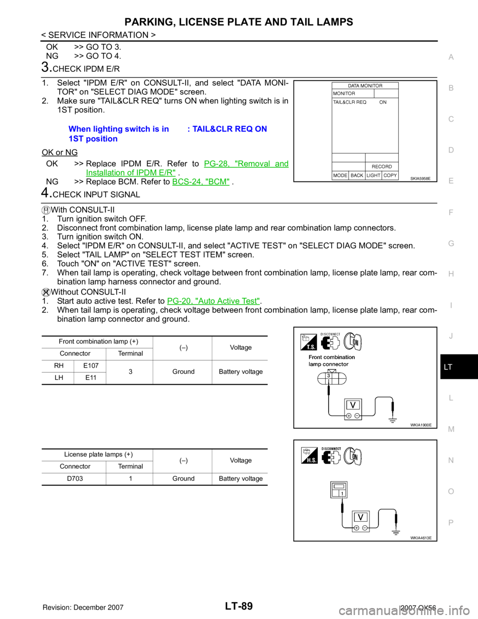
3.CHECK IPDM E/R
1. Select "IPDM E/R" on CONSULT-II, and select "DATA MONI-
TOR" on "SELECT DIAG MODE" screen.
2. Make sure "TAIL&CLR REQ" turns ON when lighting switch is in
1ST position.
OK or NG
OK >> Replace IPDM E/R. Refer to PG-28, "Removal and
Installation of IPDM E/R" .
NG >> Replace BCM. Refer to BCS-24, "
BCM" .
4.CHECK INPUT SIGNAL
With CONSULT-II
1. Turn ignition switch OFF.
2. Disconnect front combination lamp, license plate lamp and rear combination lamp connectors.
3. Turn ignition switch ON.
4. Select "IPDM E/R" on CONSULT-II, and select "ACTIVE TEST" on "SELECT DIAG MODE" screen.
5. Select "TAIL LAMP" on "SELECT TEST ITEM" screen.
6. Touch "ON" on "ACTIVE TEST" screen.
7. When tail lamp is operating, check voltage between front combination lamp, license plate lamp, rear com-
bination lamp harness connector and ground.
Without CONSULT-II
1. Start auto active test. Refer to PG-20, "
Auto Active Test".
2. When tail lamp is operating, check voltage between front combination lamp, license plate lamp, rear com-
bination lamp connector and ground.When lighting switch is in
1ST position: TAIL&CLR REQ ON
SKIA5958E
Front combination lamp (+)
(–) Voltage
Connector Terminal
RH E107
3 Ground Battery voltage
LH E11
WKIA1900E
License plate lamps (+)
(–) Voltage
Connector Terminal
D703 1 Ground Battery voltage
WKIA4613E
Page 2297 of 3061

LT-90
< SERVICE INFORMATION >
PARKING, LICENSE PLATE AND TAIL LAMPS
OK or NG
OK >> GO TO 6.
NG >> GO TO 5.
5.CHECK PARKING, LICENSE PLATE AND TAIL LAMP CIRCUIT
1. Turn ignition switch OFF.
2. Disconnect IPDM E/R connector.
3. Check continuity between IPDM E/R harness connector and
front combination lamp harness connector.
4. Check continuity between IPDM E/R connector E124 (A) and
license plate lamps connector D703 (B).
5. Check continuity between IPDM E/R harness connector and
rear combination lamp harness connector.
OK or NG
OK >> Replace IPDM E/R. Refer to PG-28, "Removal and
Installation of IPDM E/R" .
NG >> Repair harness or connector.
6.CHECK GROUND
Rear combination lamp (+)
(–) Voltage
Connector Terminal
RH B130
3 Ground Battery voltage
LH B70
WKIA1901E
IPDM E/R Front combination lamp
Continuity
Connector Terminal Connector Terminal
E124 57RH E107
3Yes
LH E11
WKIA1902E
IPDM E/R License plate lamps
Continuity
Connector Terminal Connector Terminal
A: E124 57 B: D703 1 Yes
WKIA4614E
IPDM E/R Rear combination lamp
Continuity
Connector Terminal Connector Terminal
E124 57RH B130
3 Yes
LH B70
WKIA1903E
Page 2301 of 3061

LT-94
< SERVICE INFORMATION >
TRAILER TOW
TRAILER TOW
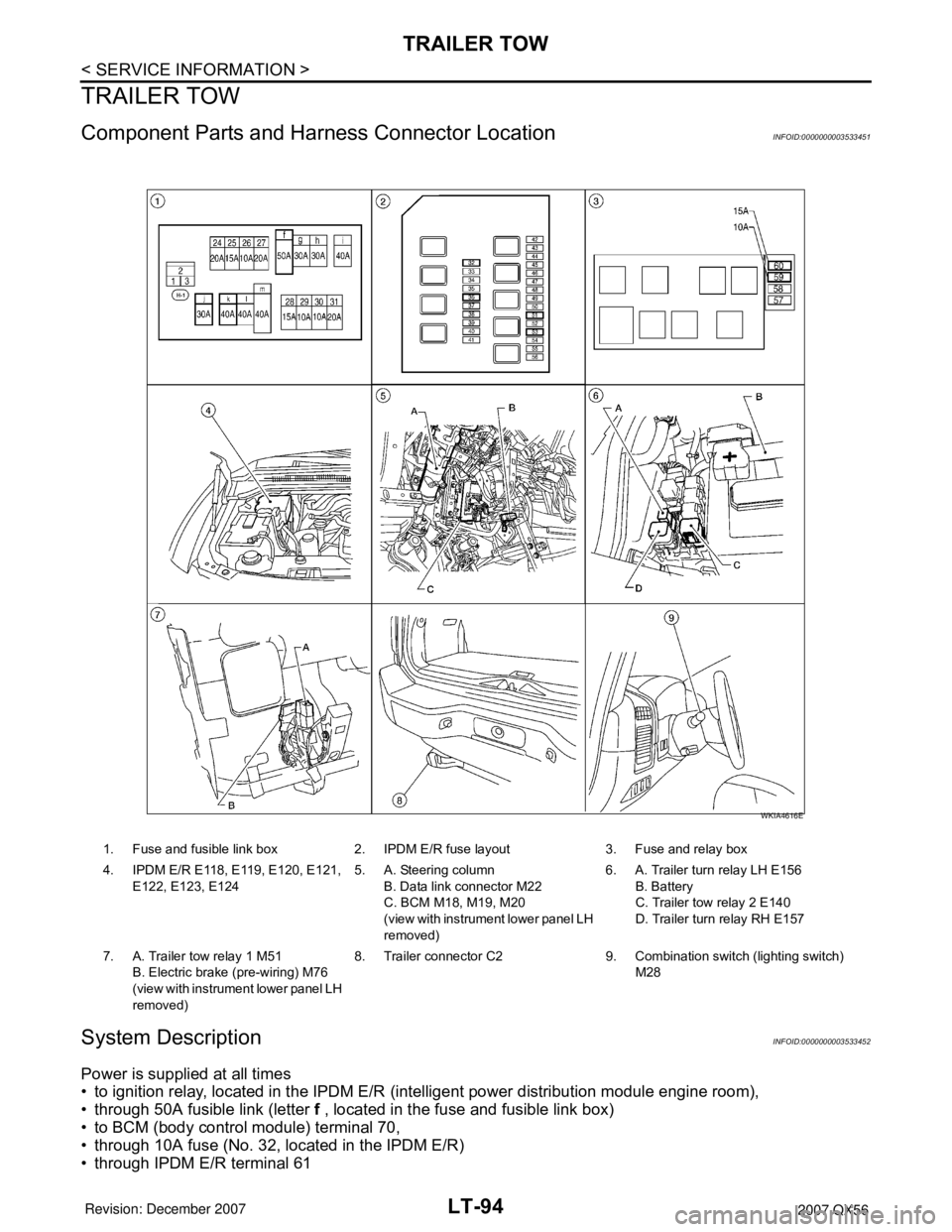
Component Parts and Harness Connector LocationINFOID:0000000003533451
System DescriptionINFOID:0000000003533452
Power is supplied at all times
• to ignition relay, located in the IPDM E/R (intelligent power distribution module engine room),
• through 50A fusible link (letter f , located in the fuse and fusible link box)
• to BCM (body control module) terminal 70,
• through 10A fuse (No. 32, located in the IPDM E/R)
• through IPDM E/R terminal 61
1. Fuse and fusible link box 2. IPDM E/R fuse layout 3. Fuse and relay box
4. IPDM E/R E118, E119, E120, E121,
E122, E123, E1245. A. Steering column
B. Data link connector M22
C. BCM M18, M19, M20
(view with instrument lower panel LH
removed)6. A. Trailer turn relay LH E156
B. Battery
C. Trailer tow relay 2 E140
D. Trailer turn relay RH E157
7. A. Trailer tow relay 1 M51
B. Electric brake (pre-wiring) M76
(view with instrument lower panel LH
removed)8. Trailer connector C2 9. Combination switch (lighting switch)
M28
WKIA4616E
Page 2310 of 3061

INTERIOR ROOM LAMP
LT-103
< SERVICE INFORMATION >
C
D
E
F
G
H
I
J
L
MA
B
LT
N
O
P
• through grounds M57, M61 and M79.
When a signal, or combination of signals is received by BCM, ground is supplied
• through BCM terminal 63
• to door mirror LH and RH terminal 13
• to front room/map lamp assembly terminal 1
• through front room/map lamp assembly terminal 2
• to personal lamps terminal 1, and
• through BCM terminal 49
• to cargo lamp terminal 1.
With power and ground supplied, the lamps illuminate.
SWITCH OPERATION
When any door switch is ON (door is opened), ground is supplied
• to front and rear step lamps LH and RH and foot lamp LH and RH terminal –
• through BCM terminal 62.
And power is supplied
• through BCM terminal 56
• to front and rear step lamps LH and RH terminal +
• to ignition keyhole illumination terminal +
• to door mirror LH and RH terminal 12
• to front room/map lamp assembly terminal 6
• to vanity lamp LH and RH terminal 1
• to personal lamp 2nd row and 3rd row terminal 3
• to cargo lamp terminal 2, and
• to foot lamp LH and RH terminal +.
When map lamp switch is ON, ground is supplied
• to front room/map lamp assembly terminal 5
• through grounds M57, M61 and M79.
When vanity lamp (LH and RH) is ON, ground is supplied
• to vanity lamp (LH and RH) terminal 2
• through grounds M57, M61 and M79.
When cargo lamp is ON, ground is supplied through cargo lamp case ground.
ROOM LAMP TIMER OPERATION
When lamp switch is in DOOR position and all conditions below are met, BCM performs timer control (maxi-
mum 30 seconds) for interior room lamp and map lamp ON/OFF.
Power is supplied
• through 10A fuse [No. 19, located in the fuse block (J/B)]
• to key switch and key lock solenoid terminal 3.
Key is removed from ignition key cylinder (key switch OFF), power will not be supplied to BCM terminal 37.
Serial data is supplied
• to BCM terminal 22
• through main power window and door lock/unlock switch terminal 14.
At the time that front door LH is opened, BCM detects that front door LH is unlocked. It determines that interior
room lamp and map lamp timer operation conditions are met, and turns the interior room lamps ON for 30 sec-
onds.
Key is in ignition key cylinder (key switch ON), power is supplied
• through key switch and key lock solenoid terminal 4
• to BCM terminal 37.
When key is removed from key switch and key lock solenoid (key switch OFF), power supply to BCM terminal
37 is terminated. BCM detects that key has been removed, determines that interior room lamp and map lamp
timer conditions are met, and turns the interior room lamps ON for 30 seconds.
When front door LH opens → closes, and the key is not inserted in the key switch and key lock solenoid (key
switch OFF), BCM terminal 47 changes between 0V (door open) → 12V (door closed). The BCM determines
that conditions for interior room lamp operation are met and turns the interior room lamp ON for 30 seconds.
Timer control is canceled under the following conditions.
• Front door LH is locked [when locked by keyfob, main power window and door lock/unlock switch, or front
door lock assembly LH (key cylinder switch)]
• Front door LH is opened (front door switch LH turns ON)
• Ignition switch ON.
INTERIOR LAMP BATTERY SAVER CONTROL
Page 2311 of 3061

LT-104
< SERVICE INFORMATION >
INTERIOR ROOM LAMP
If interior lamp is left “ON”, it will not be turned off even when door is closed.
BCM turns off interior lamp automatically to save battery 30 minutes after ignition switch is turned off.
BCM controls interior lamps listed below:
• Vanity lamp
• Room/map lamp
• Cargo lamp
• Personal lamp
• Step lamps
• Puddle lamps
• Foot lamps
• Ignition keyhole illumination
After lamps turn OFF by the battery saver system, the lamps illuminate again when
• signal received from keyfob, or main power window and door lock/unlock switch or front door lock assembly
LH (key cylinder switch) is locked or unlocked
• door is opened or closed
• key is removed from ignition key cylinder (key switch OFF) or inserted in ignition key cylinder (key switch
ON).
Interior lamp battery saver control period can be changed by the function setting of CONSULT-II.