2007 INFINITI QX56 battery
[x] Cancel search: batteryPage 2424 of 3061

PG-22
< SERVICE INFORMATION >
IPDM E/R (INTELLIGENT POWER DISTRIBUTION MODULE ENGINE ROOM)
Terminal and Reference Value for IPDM E/R
INFOID:0000000003533840
Symptom Inspection contents Possible cause
Rear window defogger
does not operate.Perform auto active
test. Does rear win-
dow defogger oper-
ate?YES • BCM signal input circuit
NO• Rear window defogger relay
• Open circuit of rear window defogger
•IPDM E/R malfunction
• Harness or connector malfunction between IPDM E/R and rear window
defogger
Any of front wipers, tail
and parking lamps, front
fog lamps, and head-
lamps (Hi, Lo) do not op-
erate.Perform auto active
test. Does system in
question operate?YES • BCM signal input system
NO• Lamp/wiper motor malfunction
• Lamp/wiper motor ground circuit malfunction
• Harness/connector malfunction between IPDM E/R and system in ques-
tion
• IPDM E/R (integrated relay) malfunction
A/C compressor does
not operate.Perform auto active
test. Does magnet
clutch operate?YES• BCM signal input circuit
• CAN communication signal between BCM and ECM
• CAN communication signal between ECM and IPDM E/R
NO• Magnet clutch malfunction
• Harness/connector malfunction between IPDM E/R and magnet clutch
• IPDM E/R (integrated relay) malfunction
Cooling fan does not op-
erate.Perform auto active
test. Does cooling fan
operate?YES• ECM signal input circuit
• CAN communication signal between ECM and IPDM E/R
NO• Cooling fan motor malfunction
• Harness/connector malfunction between IPDM E/R and cooling fan mo-
tor
• IPDM E/R (integrated relay) malfunction
Te r m i n a lWire
colorSignal nameSignal
input/
outputMeasuring condition
Reference value
(Approx.) Igni-
tion
switchOperation or condition
1 B/Y Battery power supply Input OFF — Battery voltage
2 R Battery power supply Input OFF — Battery voltage
3 BR ECM relay Output —Ignition switch ON or START Battery voltage
Ignition switch OFF or ACC 0V
4 W/L ECM relay Output —Ignition switch ON or START Battery voltage
Ignition switch OFF or ACC 0V
6LThrottle control motor
relayOutput —Ignition switch ON or START Battery voltage
Ignition switch OFF or ACC 0V
7 W/B ECM relay control Input —Ignition switch ON or START 0V
Ignition switch OFF or ACC Battery voltage
8 R/B Fuse 54 Output —Ignition switch ON or START Battery voltage
Ignition switch OFF or ACC 0V
10 GDaytime light relay
controlOutput ONDaytime light system active 0V
Daytime light system inactive Battery voltage
11 Y/B A/C compressor OutputON or
STARTA/C switch ON or defrost A/C
switchBattery voltage
A/C switch OFF or defrost A/C
switch0V
Page 2425 of 3061

IPDM E/R (INTELLIGENT POWER DISTRIBUTION MODULE ENGINE ROOM)
PG-23
< SERVICE INFORMATION >
C
D
E
F
G
H
I
J
L
MA
B
PG
N
O
P
12 L/WIgnition switch sup-
plied powerInput —OFF or ACC 0V
ON or START Battery voltage
13 B/Y Fuel pump relay Output —Ignition switch ON or START Battery voltage
Ignition switch OFF or ACC 0V
14 Y/R Fuse 49 Output —Ignition switch ON or START Battery voltage
Ignition switch OFF or ACC 0V
15 LG/B Fuse 50 Output —Ignition switch ON or START Battery voltage
Ignition switch OFF or ACC 0V
16 G Fuse 51 Output —Ignition switch ON or START Battery voltage
Ignition switch OFF or ACC 0V
17 W Fuse 55 Output —Ignition switch ON or START Battery voltage
Ignition switch OFF or ACC 0V
19 W/R Starter motor Output START — Battery voltage
21 BRIgnition switch sup-
plied powerInput —OFF or ACC 0V
START Battery voltage
22 G Battery power supply Output OFF — Battery voltage
23 GR/WDoor mirror defogger
output signalOutput —When rear defogger switch is
ONBattery voltage
When rear defogger switch is
OFF0V
24 L/B Cooling fan relay Output —Conditions correct for cooling
fan operationBattery voltage
Conditions not correct for
cooling fan operation0V
26 P/LHeadlamp aiming mo-
torsOutput —Lighting
switch 2nd
position, or
AUTO, head-
lamp aiming
switch in po-
sitionOFF Battery voltage
ON 0V
27 W/B Fuse 38 Output —Ignition switch ON or START Battery voltage
Ignition switch OFF or ACC 0V
30 W Fuse 53 Output —Ignition switch ON or START Battery voltage
Ignition switch OFF or ACC 0V
32 LWiper low speed sig-
nalOutputON or
STARTWiper switchOFF Battery voltage
LO or INT 0V
35 L/BWiper high speed sig-
nalOutputON or
STARTWiper switchOFF, LO, INT Battery voltage
HI 0V
38 B Ground Input — — 0V
39 L CAN-L — ON — —
40 P CAN-H — ON — —
41 Y/B Hood switch Input —Hood closed OFF 0V
Hood open ON Battery voltage Te r m i n a lWire
colorSignal nameSignal
input/
outputMeasuring condition
Reference value
(Approx.) Igni-
tion
switchOperation or condition
Page 2426 of 3061

PG-24
< SERVICE INFORMATION >
IPDM E/R (INTELLIGENT POWER DISTRIBUTION MODULE ENGINE ROOM)
43 L/Y Wiper auto stop signal InputON or
STARTWiper switch OFF, LO, INT Battery voltage
44 BRDaytime light relay
controlInput ONDaytime light system active 0V
Daytime light system inactive Battery voltage
45 G/W Horn relay control Input ONWhen door locks are operated
using key fob (OFF → ON)*1Battery voltage → 0V
46 GRFuel pump relay con-
trolInput —Ignition switch ON or START 0V
Ignition switch OFF or ACC Battery voltage
47 OThrottle control motor
relay controlInput —Ignition switch ON or START 0V
Ignition switch OFF or ACC Battery voltage
48 B/RStarter relay (inhibit
switch)InputON or
STARTSelector lever in "P" or "N" 0V
Selector lever any other posi-
tionBattery voltage
49 R/L Trailer tow relay Output ONLighting
switch must
be in the 1st
positionOFF 0V
ON Battery voltage
50 W/R Front fog lamp (LH) OutputON or
STARTLighting
switch must
be in the 2nd
position
(LOW beam
is ON) and
the front fog
lamp switchOFF 0V
ON Battery voltage
51 W/R Front fog lamp (RH) OutputON or
STARTLighting
switch must
be in the 2nd
position
(LOW beam
is ON) and
the front fog
lamp switchOFF 0V
ON Battery voltage
52 LLH low beam head-
lampOutput — Lighting switch in 2nd position Battery voltage
54 R/YRH low beam head-
lampOutput — Lighting switch in 2nd position Battery voltage
55 GLH high beam head-
lampOutput —Lighting switch in 2nd position
and placed in HIGH or PASS
positionBattery voltage
56L/W*2
Y*3LH high beam head-
lampOutput —Lighting switch in 2nd position
and placed in HIGH or PASS
positionBattery voltage
57 R/LParking, license, and
tail lampOutput ONLighting
switch 1st po-
sitionOFF 0V
ON Battery voltage
59 B Ground Input — — 0V
60 B/WRear window defog-
ger relayOutputON or
STARTRear defogger switch ON Battery voltage
Rear defogger switch OFF 0V Te r m i n a lWire
colorSignal nameSignal
input/
outputMeasuring condition
Reference value
(Approx.) Igni-
tion
switchOperation or condition
Page 2427 of 3061

IPDM E/R (INTELLIGENT POWER DISTRIBUTION MODULE ENGINE ROOM)
PG-25
< SERVICE INFORMATION >
C
D
E
F
G
H
I
J
L
MA
B
PG
N
O
P
*1: When horn reminder is ON
*2: L/W is for U.S.A.
*3: Y is for Canada61 BR Fuse 32 Output —Ignition switch ON or START Battery voltage
Ignition switch OFF or ACC 0V Te r m i n a lWire
colorSignal nameSignal
input/
outputMeasuring condition
Reference value
(Approx.) Igni-
tion
switchOperation or condition
Page 2429 of 3061

IPDM E/R (INTELLIGENT POWER DISTRIBUTION MODULE ENGINE ROOM)
PG-27
< SERVICE INFORMATION >
C
D
E
F
G
H
I
J
L
MA
B
PG
N
O
P
OK or NG
OK >> GO TO 2.
NG >> Replace fuse or fusible link.
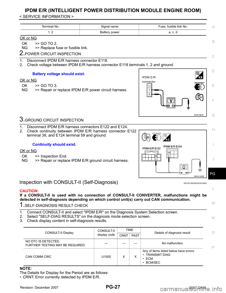
2.POWER CIRCUIT INSPECTION
1. Disconnect IPDM E/R harness connector E118.
2. Check voltage between IPDM E/R harness connector E118 terminals 1, 2 and ground.
OK or NG
OK >> GO TO 3.
NG >> Repair or replace IPDM E/R power circuit harness.
3.GROUND CIRCUIT INSPECTION
1. Disconnect IPDM E/R harness connectors E122 and E124.
2. Check continuity between IPDM E/R harness connector E122
terminal 38, and E124 terminal 59 and ground.
OK or NG
OK >> Inspection End.
NG >> Repair or replace IPDM E/R ground circuit harness.
Inspection with CONSULT-II (Self-Diagnosis)INFOID:0000000003533843
CAUTION:
If a CONSULT-II is used with no connection of CONSULT-II CONVERTER, malfunctions might be
detected in self-diagnosis depending on which control unit(s) carry out CAN communication.
1.SELF-DIAGNOSIS RESULT CHECK
1. Connect CONSULT-II and select "IPDM E/R" on the Diagnosis System Selection screen.
2. Select "SELF-DIAG RESULTS" on the diagnosis mode selection screen.
3. Check display content in self-diagnosis results.
NOTE:
The Details for Display for the Period are as follows:
• CRNT: Error currently detected by IPDM E/R.
Terminal No. Signal name Fuse, fusible link No.
1, 2 Battery power a, c, d
Battery voltage should exist.
SKIA1987E
Continuity should exist.
WKIA1453E
CONSULT-II DisplayCONSULT-II
display codeTIME
Details of diagnosis result
CRNT PAST
NO DTC IS DETECTED.
FURTHER TESTING MAY BE REQUIRED.——— No malfunction
CAN COMM CIRC U1000 X XAny of items listed below have errors:
• TRANSMIT DIAG
•ECM
• BCM/SEC
Page 2430 of 3061

PG-28
< SERVICE INFORMATION >
IPDM E/R (INTELLIGENT POWER DISTRIBUTION MODULE ENGINE ROOM)
• PAST: Error detected in the past and stored in IPDM E/R memory.
Contents displayed
NO DTC DETECTED. FURTHER TESTING MAY BE REQUIRED.>>Inspection End.
CAN COMM CIRC>>Print out the self-diagnosis result and refer to LAN-40
.
Removal and Installation of IPDM E/RINFOID:0000000003533844
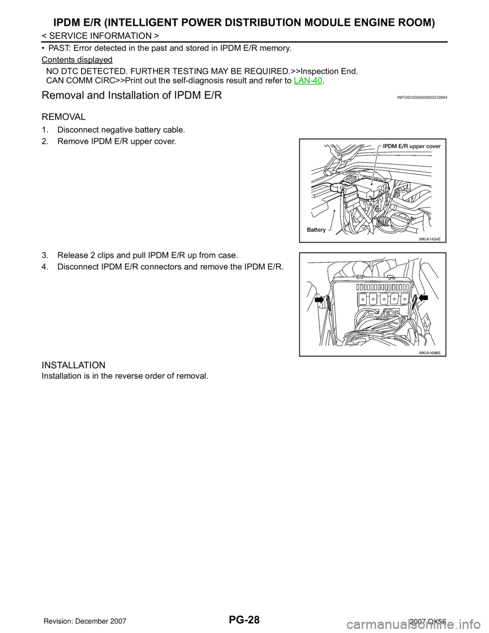
REMOVAL
1. Disconnect negative battery cable.
2. Remove IPDM E/R upper cover.
3. Release 2 clips and pull IPDM E/R up from case.
4. Disconnect IPDM E/R connectors and remove the IPDM E/R.
INSTALLATION
Installation is in the reverse order of removal.
WKIA1454E
WKIA1696E
Page 2534 of 3061

RF-2
< SERVICE INFORMATION >
PRECAUTIONS
SERVICE INFORMATION
PRECAUTIONS
Precaution for Supplemental Restraint System (SRS) "AIR BAG" and "SEAT BELT
PRE-TENSIONER"
INFOID:0000000003533088
The Supplemental Restraint System such as “AIR BAG” and “SEAT BELT PRE-TENSIONER”, used along
with a front seat belt, helps to reduce the risk or severity of injury to the driver and front passenger for certain
types of collision. This system includes seat belt switch inputs and dual stage front air bag modules. The SRS
system uses the seat belt switches to determine the front air bag deployment, and may only deploy one front
air bag, depending on the severity of a collision and whether the front occupants are belted or unbelted.
Information necessary to service the system safely is included in the SRS and SB section of this Service Man-
ual.
WARNING:
• To avoid rendering the SRS inoperative, which could increase the risk of personal injury or death in
the event of a collision which would result in air bag inflation, all maintenance must be performed by
an authorized NISSAN/INFINITI dealer.
• Improper maintenance, including incorrect removal and installation of the SRS, can lead to personal
injury caused by unintentional activation of the system. For removal of Spiral Cable and Air Bag
Module, see the SRS section.
• Do not use electrical test equipment on any circuit related to the SRS unless instructed to in this
Service Manual. SRS wiring harnesses can be identified by yellow and/or orange harnesses or har-
ness connectors.
PrecautionINFOID:0000000003533089
• Disconnect both battery cables in advance.
• Never tamper with or force air bag lid open, as this may adversely affect air bag performance.
• Be careful not to scratch pad and other parts.
• When removing or disassembling any part, be careful not to damage or deform it. Protect parts which may
get in the way with cloth.
• When removing parts with a screwdriver or other tool, protect parts by wrapping them with vinyl or tape.
• Keep removed parts protected with cloth.
• If a clip is deformed or damaged, replace it.
• If an unreusable part is removed, replace it with a new one.
• Tighten bolts and nuts firmly to the specified torque.
• After re-assembly has been completed, make sure each part functions correctly.
• Remove stains in the following way.
Water-soluble stains:
Dip a soft cloth in warm water, and then squeeze it tightly. After wiping the stain, wipe with a soft dry cloth.
Oil stain:
Dissolve a synthetic detergent in warm water (density of 2 to 3% or less), dip the cloth, then clean off the stain
with the cloth. Next, dip the cloth in fresh water and squeeze it tightly. Then clean off the detergent completely.
Then wipe the area with a soft dry cloth.
• Do not use any organic solvent, such as thinner or benzine.
Page 2546 of 3061

RF-14
< SERVICE INFORMATION >
SUNROOF
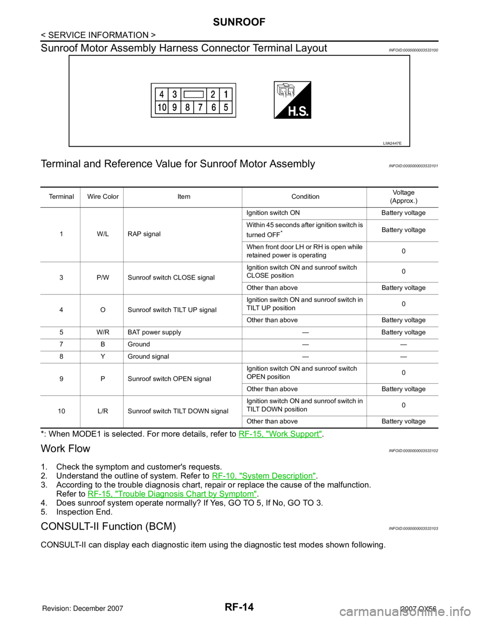
Sunroof Motor Assembly Harness Connector Terminal Layout
INFOID:0000000003533100
Terminal and Reference Value for Sunroof Motor AssemblyINFOID:0000000003533101
*: When MODE1 is selected. For more details, refer to RF-15, "Work Support".
Work FlowINFOID:0000000003533102
1. Check the symptom and customer's requests.
2. Understand the outline of system. Refer to RF-10, "
System Description".
3. According to the trouble diagnosis chart, repair or replace the cause of the malfunction.
Refer to RF-15, "
Trouble Diagnosis Chart by Symptom".
4. Does sunroof system operate normally? If Yes, GO TO 5, If No, GO TO 3.
5. Inspection End.
CONSULT-II Function (BCM)INFOID:0000000003533103
CONSULT-II can display each diagnostic item using the diagnostic test modes shown following.
LIIA2447E
Terminal Wire Color Item ConditionVol tag e
(Approx.)
1 W/L RAP signalIgnition switch ON Battery voltage
Within 45 seconds after ignition switch is
turned OFF
*Battery voltage
When front door LH or RH is open while
retained power is operating0
3 P/W Sunroof switch CLOSE signalIgnition switch ON and sunroof switch
CLOSE position0
Other than above Battery voltage
4 O Sunroof switch TILT UP signalIgnition switch ON and sunroof switch in
TILT UP position0
Other than above Battery voltage
5 W/R BAT power supply — Battery voltage
7 B Ground — —
8 Y Ground signal — —
9 P Sunroof switch OPEN signalIgnition switch ON and sunroof switch
OPEN position0
Other than above Battery voltage
10 L/R Sunroof switch TILT DOWN signalIgnition switch ON and sunroof switch in
TILT DOWN position0
Other than above Battery voltage