Page 2841 of 3061

ALL-MODE 4WD SYSTEM
TF-19
< SERVICE INFORMATION >
C
E
F
G
H
I
J
K
L
MA
B
TF
N
O
P
*: When 4WD warning lamp is ON, all the 4WD shift indicator lamps turn OFF.
ATP WARNING LAMP
Even if A/T selector lever is in “P” position, vehicle may move because A/T parking mechanism does not oper-
ate when transfer is under neutral condition. ATP warning lamp is turned on so as to indicate this condition to
the driver.
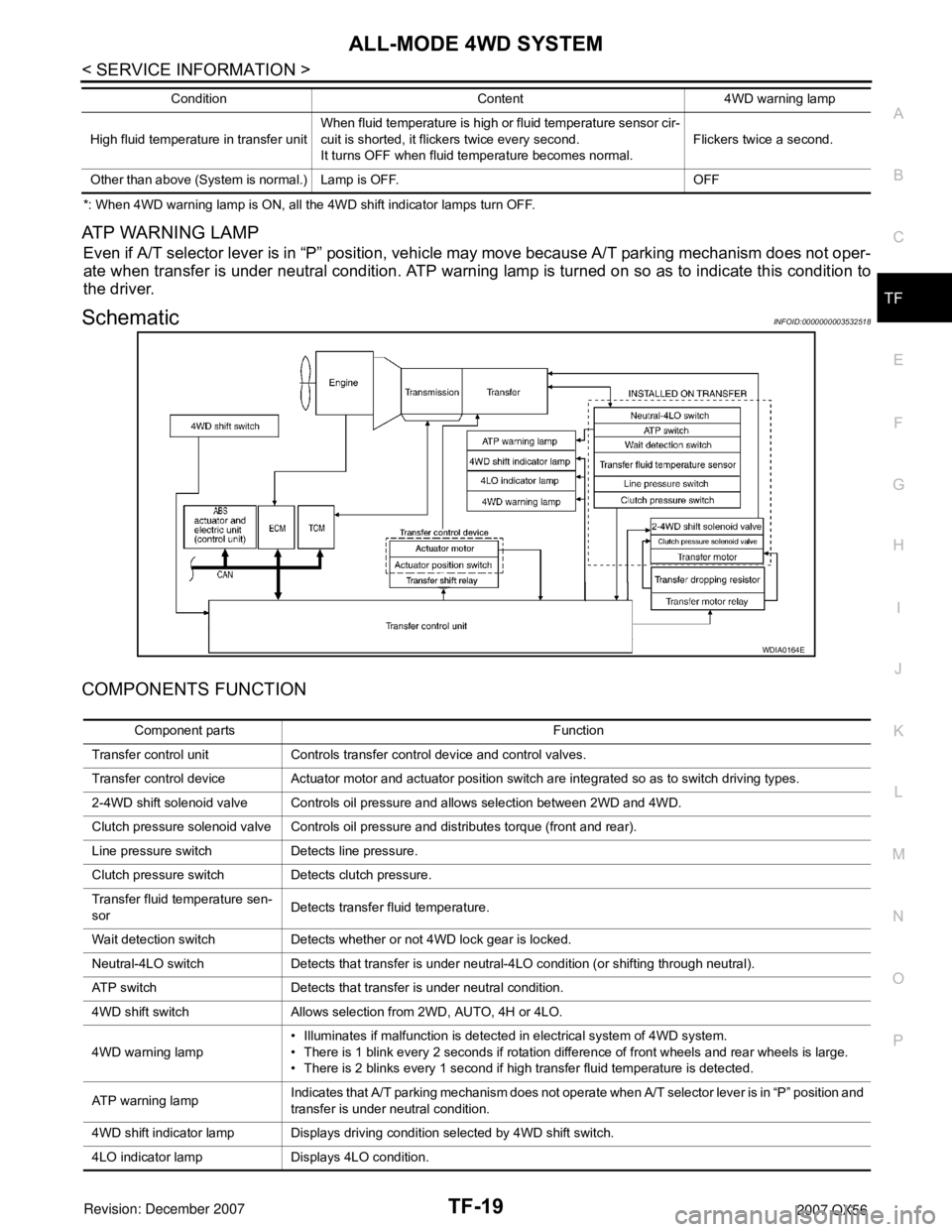
SchematicINFOID:0000000003532518
COMPONENTS FUNCTION
High fluid temperature in transfer unitWhen fluid temperature is high or fluid temperature sensor cir-
cuit is shorted, it flickers twice every second.
It turns OFF when fluid temperature becomes normal.Flickers twice a second.
Other than above (System is normal.) Lamp is OFF. OFFCondition Content 4WD warning lamp
WDIA0164E
Component parts Function
Transfer control unit Controls transfer control device and control valves.
Transfer control device Actuator motor and actuator position switch are integrated so as to switch driving types.
2-4WD shift solenoid valve Controls oil pressure and allows selection between 2WD and 4WD.
Clutch pressure solenoid valve Controls oil pressure and distributes torque (front and rear).
Line pressure switch Detects line pressure.
Clutch pressure switch Detects clutch pressure.
Transfer fluid temperature sen-
sorDetects transfer fluid temperature.
Wait detection switch Detects whether or not 4WD lock gear is locked.
Neutral-4LO switch Detects that transfer is under neutral-4LO condition (or shifting through neutral).
ATP switch Detects that transfer is under neutral condition.
4WD shift switch Allows selection from 2WD, AUTO, 4H or 4LO.
4WD warning lamp• Illuminates if malfunction is detected in electrical system of 4WD system.
• There is 1 blink every 2 seconds if rotation difference of front wheels and rear wheels is large.
• There is 2 blinks every 1 second if high transfer fluid temperature is detected.
AT P w a r n i n g l a m pIndicates that A/T parking mechanism does not operate when A/T selector lever is in “P” position and
transfer is under neutral condition.
4WD shift indicator lamp Displays driving condition selected by 4WD shift switch.
4LO indicator lamp Displays 4LO condition.
Page 2866 of 3061
![INFINITI QX56 2007 Factory Service Manual TF-44
< SERVICE INFORMATION >
TROUBLE DIAGNOSIS
CAUTION:
• If “CAN COMM CIRCUIT [U1000]” is displayed with other DTCs, first perform the trouble diagnosis for CAN communication
line.
• If “V INFINITI QX56 2007 Factory Service Manual TF-44
< SERVICE INFORMATION >
TROUBLE DIAGNOSIS
CAUTION:
• If “CAN COMM CIRCUIT [U1000]” is displayed with other DTCs, first perform the trouble diagnosis for CAN communication
line.
• If “V](/manual-img/42/57029/w960_57029-2865.png)
TF-44
< SERVICE INFORMATION >
TROUBLE DIAGNOSIS
CAUTION:
• If “CAN COMM CIRCUIT [U1000]” is displayed with other DTCs, first perform the trouble diagnosis for CAN communication
line.
• If “VHCL SPEED SEN·AT [P1808]”, “ABS OP SIG [P1830]”, “VDC OP SIG [P1831]” or “TCS OP SIG [P1832]” is displayed, first
perform the trouble diagnosis for ABS system.
• If “VHCL SPEED SEN·AT [P1808]”, is displayed, first perform the trouble diagnosis for A/T system.
NOTE:
• If "SHIFT ACT POSI SW [P1818]" or “SHIFT ACT CIR [P1819]” is displayed, first erase self-diagnostic results. ("SHIFT ACT POSI SW
[P1818]" or “SHIFT ACT CIR [P1819]” may be displayed after installing transfer control unit or transfer assembly.)
• If “CL PRES SW [P1827]” or “LINE PRES SW [P1828]” is displayed only while driving in reverse, check the continuity of “R” position
on A/T PNP switch. When there is nothing wrong with the electrical system, check the hydraulic system.
How to Erase Self-diagnostic Results
1. Perform applicable inspection of malfunctioning item and then repair or replace.
SHIFT ACT CIR
[P1819]• Transfer control device actuator circuit is shorted or open. (Mal-
functions are detected when transfer shift relay circuit is open/
shorted or relay monitor circuit is open/shorted.)
• Malfunction occurs in transfer control device drive circuit.
• Malfunction is detected in transfer shut off relay.TF-72, "Transfer Control Device"
Malfunction is detected in transfer shut off relay.TF-51, "Power Supply Circuit for
Transfer Control Unit"
ENGINE SPEED SIG
[P1820]• Malfunction is detected in engine speed signal that is output from
ECM through CAN communication.
• Improper signal is input while driving.TF-76, "Engine Speed Signal
(ECM)"
DUTY SOLENOID
[P1822]• Proper voltage is not applied to clutch pressure solenoid valve
due to open or short circuit.TF-76, "Clutch Pressure Sole-
noid"
2-4WD SOLENOID
[P1823]• Proper voltage is not applied to 2-4WD solenoid valve due to open
or short circuit.TF-80, "2-4WD Solenoid"
MOTOR RELAY
[P1824]• Motor does not operate properly due to open or short circuit in
transfer motor or motor relay.TF-84, "Transfer Motor"
OIL TEMP SEN
[P1826]• Signal voltage from fluid temperature sensor is abnormally high
(Transfer fluid temperature is abnormally low) while driving.TF-90, "Transfer Fluid Tempera-
ture"
CLUTCH PRES SW
[P1827]• Improper signal from clutch pressure switch is input due to open or
short circuit.
• Malfunction occurs in clutch pressure switch or hydraulic circuit.TF-92, "Clutch Pressure Switch"
LINE PRES SW
[P1828]• Improper signal from line pressure switch is input due to open or
short circuit.
• Malfunction occurs in line pressure switch or hydraulic circuit.TF-94, "Line Pressure Switch"
THROTTLE POSI SEN
[P1829]• Malfunction is detected in accelerator pedal position signal that is
output from ECM through CAN communication.
• Signal voltage from accelerator pedal position sensor is abnormal-
ly high or low.TF-97, "Throttle Position Signal
(ECM)"
ABS OP SIG
[P1830]• Malfunction is detected in ABS operation signal that is output from
ABS actuator and electric unit (control unit) through CAN commu-
nication.TF-97, "ABS Operation Signal
(ABS)"
VDC OP SIG
[P1831]• Malfunction is detected in VDC operation signal that is output from
ABS actuator and electric unit (control unit) through CAN commu-
nication.TF-98, "VDC Operation Signal
(ABS)"
TCS OP SIG
[P1832]• Malfunction is detected in TCS operation signal that is output from
ABS through CAN communication.TF-98, "TCS Operation Signal
(ABS)"
CAN COMM CIRCUIT
[U1000]• Malfunction has been detected from CAN communication line.TF-99, "CAN Communication
Line"
NO DTC IS DETECTED.
FURTHER TESTING MAY
BE REQUIRED.• No NG item has been detected. — Items (CONSULT-II screen
terms)Diagnostic item is detected when... Check item
Page 2938 of 3061
TF-116
< SERVICE INFORMATION >
FRONT OIL SEAL
FRONT OIL SEAL
Removal and InstallationINFOID:0000000003532563
REMOVAL
1. Partially drain the transfer fluid. Refer to TF-11, "Replacement".
2. Remove the front propeller shaft. Refer to PR-4, "
Removal and Installation".
3. Remove the companion flange self-lock nut using Tool.
4. Put a matching mark on top of the front drive shaft in line with
the mark on the companion flange.
CAUTION:
Use paint to make the matching mark on the front drive
shaft. Do not damage the front drive shaft.
5. Remove the companion flange using suitable tool.
6. Remove the oil seal from the front case using Tool.
CAUTION:
Do not damage front case.
INSTALLATION
Tool number : KV40104000 ( — )
SDIA2657E
SDIA2658E
WDIA0193E
Tool number : KV381054S0 (J-34286)
LDIA0144E
Page 2939 of 3061
FRONT OIL SEAL
TF-117
< SERVICE INFORMATION >
C
E
F
G
H
I
J
K
L
MA
B
TF
N
O
P
1. Install the new oil seal until it is flush with the end face of the
front case using Tool.
CAUTION:
• Do not reuse oil seal.
• Apply petroleum jelly to oil seal.
2. Align the matching mark of the front drive shaft with the match-
ing mark of the companion flange, then install the companion
flange.
3. Install the new self-lock nut. Tighten to the specified torque
using Tool. Refer to TF-128, "
Disassembly and Assembly".
CAUTION:
Do not reuse self-lock nut.
4. Install the front propeller shaft. Refer to PR-4, "
Removal and
Installation".
5. Refill the transfer with fluid and check fluid level. Refer to TF-11
.
6. Check the transfer for fluid leakage. Refer to TF-11, "
Inspec-
tion". Tool number : KV38100500 ( — )
SDIA2662E
SDIA2658E
Tool number : KV40104000 ( — )
LDIA0147E
Page 2940 of 3061
TF-118
< SERVICE INFORMATION >
REAR OIL SEAL
REAR OIL SEAL
Removal and InstallationINFOID:0000000003532564
REMOVAL
1. Partially drain the transfer fluid. Refer to TF-11, "Replacement".
2. Remove the rear propeller shaft. Refer to PR-8, "
Removal and Installation".
3. Remove the dust cover from the rear case.
CAUTION:
Do not damage the rear case.
4. Remove the rear oil seal from the rear case using Tool.
CAUTION:
Do not damage the rear case.
INSTALLATION
1. Install the new oil seal until it is flush with the end face of the rear
case using Tool.
CAUTION:
• Do not reuse oil seal.
• Apply petroleum jelly to oil seal.
2. Apply petroleum jelly to the circumference of the new dust cover.
Position the new dust cover using the identification mark as
shown.
CAUTION:
• Do not reuse dust cover.
• Position the identification mark at the position shown.
WDIA0127E
Tool number : KV381054S0 (J-34286)
LDIA0139E
Tool number : ST30720000 (J-25405)
LDIA0140E
SDIA3436E
Page 2941 of 3061
REAR OIL SEAL
TF-119
< SERVICE INFORMATION >
C
E
F
G
H
I
J
K
L
MA
B
TF
N
O
P
3. Install the new dust cover to the rear case using Tool.
CAUTION:
• Do not reuse dust cover.
• Apply petroleum jelly to dust cover.
4. Install the rear propeller shaft. Refer to PR-8, "
Removal and
Installation".
5. Refill the transfer with fluid and check fluid level. Refer to TF-11,
"Replacement".
6. Check the transfer for fluid leakage. Refer to TF-11, "
Inspec-
tion". Tool number : KV40105310 ( — )
PDIA0116E
Page 2942 of 3061
TF-120
< SERVICE INFORMATION >
SIDE OIL SEAL
SIDE OIL SEAL
Removal and InstallationINFOID:0000000003532565
REMOVAL
1. Remove the front propeller shaft. Refer to PR-4, "Removal and Installation".
2. Remove the companion flange. Refer to TF-116, "
Removal and Installation".
3. Remove the transfer control device from the transfer assembly. Refer to TF-121, "
Removal and Installa-
tion".
4. Remove the side oil seal using suitable tool.
CAUTION:
Do not damage shift cross.
INSTALLATION
1. Install the new side oil seal until it is flush with the end face of
case using Tool.
CAUTION:
• Do not reuse oil seal.
• Apply petroleum jelly to oil seal.
2. Install the transfer control device to the transfer assembly. Refer
to TF-121, "
Removal and Installation".
3. Install the companion flange. Refer to TF-116, "
Removal and
Installation".
4. Install the front propeller shaft. Refer to PR-4, "
Removal and Installation".
SDIA2666E
Tool number : ST22360002 (J-25679-01)
SDIA2665E
Page 2947 of 3061

TRANSFER MOTOR
TF-125
< SERVICE INFORMATION >
C
E
F
G
H
I
J
K
L
MA
B
TF
N
O
P
TRANSFER MOTOR
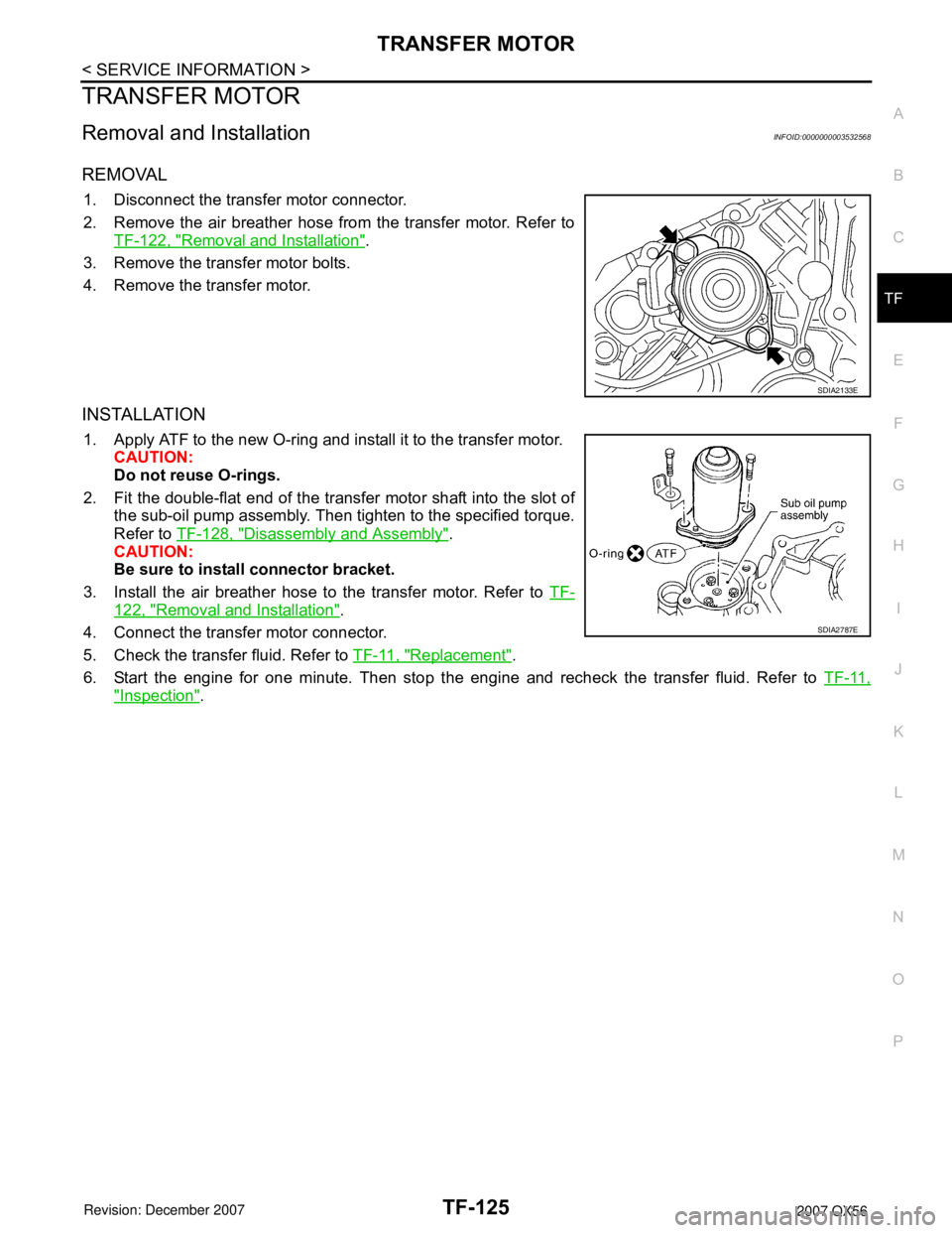
Removal and InstallationINFOID:0000000003532568
REMOVAL
1. Disconnect the transfer motor connector.
2. Remove the air breather hose from the transfer motor. Refer to
TF-122, "
Removal and Installation".
3. Remove the transfer motor bolts.
4. Remove the transfer motor.
INSTALLATION
1. Apply ATF to the new O-ring and install it to the transfer motor.
CAUTION:
Do not reuse O-rings.
2. Fit the double-flat end of the transfer motor shaft into the slot of
the sub-oil pump assembly. Then tighten to the specified torque.
Refer to TF-128, "
Disassembly and Assembly".
CAUTION:
Be sure to install connector bracket.
3. Install the air breather hose to the transfer motor. Refer to TF-
122, "Removal and Installation".
4. Connect the transfer motor connector.
5. Check the transfer fluid. Refer to TF-11, "
Replacement".
6. Start the engine for one minute. Then stop the engine and recheck the transfer fluid. Refer to TF-11,
"Inspection".
SDIA2133E
SDIA2787E