Page 2984 of 3061
TF-162
< SERVICE INFORMATION >
TRANSFER ASSEMBLY
15. Install the 2-4 sleeve and L-H sleeve to each fork.
16. Install the shift cross to the front case.
17. While aligning the L-H sleeve with the planetary carrier, install
the shift rod assembly to the front case.
18. Apply liquid gasket to the entire center case mating surface of
the front case assembly as shown.
•Use Genuine Anaerobic Liquid Gasket or equivalent.
Refer to GI-45
.
CAUTION:
Remove all foreign materials such as water, oil and grease
from center case and front case mating surfaces.
19. Install the center case assembly to the front case assembly.
CAUTION:
Do not damage mainshaft end.
20. Tap the center case lightly and press-fit the front drive shaft
bearing into the front case.
SMT992C
SDIA2140E
WDIA0157E
SDIA2138E
Page 2985 of 3061

TRANSFER ASSEMBLY
TF-163
< SERVICE INFORMATION >
C
E
F
G
H
I
J
K
L
MA
B
TF
N
O
P
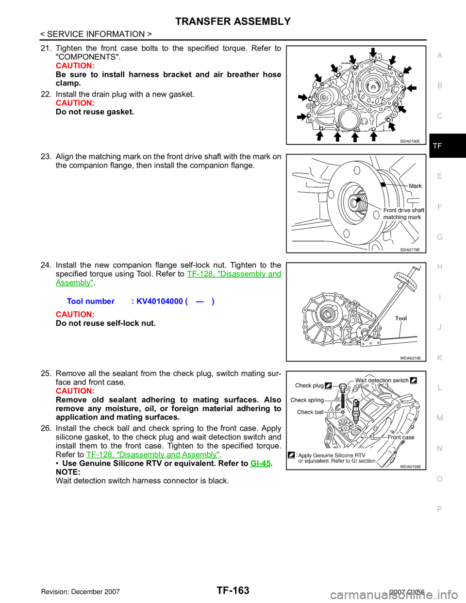
21. Tighten the front case bolts to the specified torque. Refer to
"COMPONENTS".
CAUTION:
Be sure to install harness bracket and air breather hose
clamp.
22. Install the drain plug with a new gasket.
CAUTION:
Do not reuse gasket.
23. Align the matching mark on the front drive shaft with the mark on
the companion flange, then install the companion flange.
24. Install the new companion flange self-lock nut. Tighten to the
specified torque using Tool. Refer to TF-128, "
Disassembly and
Assembly".
CAUTION:
Do not reuse self-lock nut.
25. Remove all the sealant from the check plug, switch mating sur-
face and front case.
CAUTION:
Remove old sealant adhering to mating surfaces. Also
remove any moisture, oil, or foreign material adhering to
application and mating surfaces.
26. Install the check ball and check spring to the front case. Apply
silicone gasket, to the check plug and wait detection switch and
install them to the front case. Tighten to the specified torque.
Refer to TF-128, "
Disassembly and Assembly".
•Use Genuine Silicone RTV or equivalent. Refer to GI-45
.
NOTE:
Wait detection switch harness connector is black.
SDIA2100E
SDIA2779E
Tool number : KV40104000 ( — )
WDIA0219E
WDIA0158E
Page 2986 of 3061

TF-164
< SERVICE INFORMATION >
TRANSFER ASSEMBLY
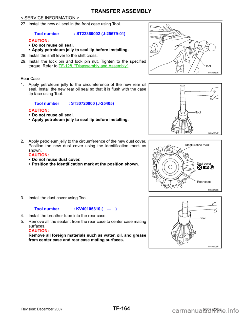
27. Install the new oil seal in the front case using Tool.
CAUTION:
• Do not reuse oil seal.
• Apply petroleum jelly to seal lip before installing.
28. Install the shift lever to the shift cross.
29. Install the lock pin and lock pin nut. Tighten to the specified
torque. Refer to TF-128, "
Disassembly and Assembly".
Rear Case
1. Apply petroleum jelly to the circumference of the new rear oil
seal. Install the new rear oil seal so that it is flush with the case
tip face using Tool.
CAUTION:
• Do not reuse oil seal.
• Apply petroleum jelly to seal lip before installing.
2. Apply petroleum jelly to the circumference of the new dust cover.
Position the new dust cover using the identification mark as
shown.
CAUTION:
• Do not reuse dust cover.
• Position the identification mark at the position shown.
3. Install the dust cover using Tool.
4. Install the breather tube into the rear case.
5. Remove all the sealant from the rear case to center case mating
surfaces.
CAUTION:
Remove all foreign materials such as water, oil, and grease
from center case and rear case mating surfaces.Tool number : ST22360002 (J-25679-01)
SDIA2182E
Tool number : ST30720000 (J-25405)
SDIA2204E
SDIA3436E
Tool number : KV40105310 ( — )
SDIA2205E
Page 2988 of 3061

TF-166
< SERVICE INFORMATION >
SERVICE DATA AND SPECIFICATIONS (SDS)
SERVICE DATA AND SPECIFICATIONS (SDS)
General SpecificationINFOID:0000000003532572
Inspection and AdjustmentINFOID:0000000003532573
CLEARANCE BETWEEN INNER GEAR AND OUTER GEAR
Unit: mm (in)
CLUTCH
Unit: mm (in)
PINION GEAR END PLAY
Unit: mm (in)
CLEARANCE BETWEEN SHIFT FORK AND SLEEVE
Unit: mm (in)
SELECTIVE PARTS
Sub-oil Pump
Unit: mm (in)
*: Always check with the Parts Department for the latest parts information.
Main Oil Pump
Applied modelVK56DE
Transfer modelAT X 1 4 B
Fluid capacity (Approx.)
(US qt, lmp qt)3.0 (3-1/8, 2-5/8)
Gear ratioHigh 1.000
Low 2.596
Number of teethSun gear 57
Internal gear 91
Front drive sprocket 38
Front drive shaft 38
Item Specification
Main oil pump 0.015 - 0.035 (0.0006 - 0.0014)
Sub-oil pump 0.015 - 0.035 (0.0006 - 0.0014)
Item Limit value
Drive plate1.4 (0.055)
Item Standard
Pinion gear end play 0.1 - 0.7 (0.004 - 0.028)
Item Standard
Shift fork and sleeve Less than 0.36 (0.0142)
Gear thicknessPart number*
Inner gear Outer gear
9.27 - 9.28 (0.3650 - 0.3654) 31346 0W462 31347 0W462
9.28 - 9.29 (0.3654 - 0.3657) 31346 0W461 31347 0W461
9.29 - 9.30 (0.3657 - 0.3661) 31346 0W460 31347 0W460
Page 3056 of 3061
REAR WIPER AND WASHER SYSTEM
WW-39
< SERVICE INFORMATION >
C
D
E
F
G
H
I
J
L
MA
B
WW
N
O
P
Rear Washer Tube LayoutINFOID:0000000003533585
NOTE:
Connect the check valve (2) to the washer fluid reservoir tube (1) so
that the directional arrow on the check valve (2) points towards the
washer nozzle tube (3).
Rear Washer NozzleINFOID:0000000003533586
REMOVAL AND INSTALLATION
Removal
1. Remove the rear spoiler. Refer to EI-25.
2. Release retaining clips, and remove washer nozzle.
Installation
Installation is in the reverse order of removal.
Rear Wiper and Washer SwitchINFOID:0000000003533587
REMOVAL AND INSTALLATION
Refer to IP-10, "Removal and Installation".
WKIA4566E
1. Rear washer nozzle 2. Washer fluid reservoir 3. Check valve
WKIA4242E
LKIA0418E