2007 INFINITI QX56 display
[x] Cancel search: displayPage 2240 of 3061
HEADLAMP (FOR CANADA) - DAYTIME LIGHT SYSTEM -
LT-33
< SERVICE INFORMATION >
C
D
E
F
G
H
I
J
L
MA
B
LT
N
O
P
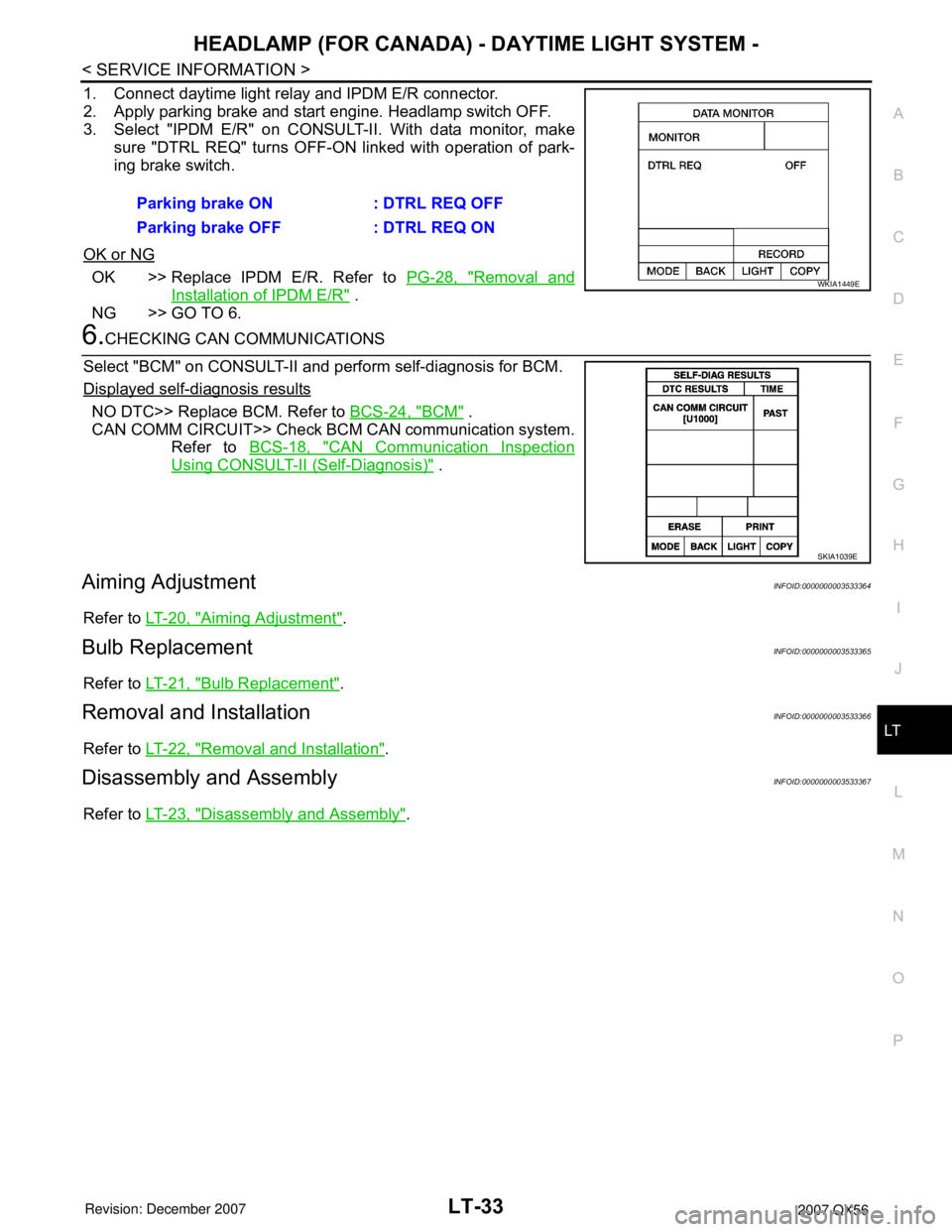
1. Connect daytime light relay and IPDM E/R connector.
2. Apply parking brake and start engine. Headlamp switch OFF.
3. Select "IPDM E/R" on CONSULT-II. With data monitor, make
sure "DTRL REQ" turns OFF-ON linked with operation of park-
ing brake switch.
OK or NG
OK >> Replace IPDM E/R. Refer to PG-28, "Removal and
Installation of IPDM E/R" .
NG >> GO TO 6.
6.CHECKING CAN COMMUNICATIONS
Select "BCM" on CONSULT-II and perform self-diagnosis for BCM.
Displayed self-diagnosis results
NO DTC>> Replace BCM. Refer to BCS-24, "BCM" .
CAN COMM CIRCUIT>> Check BCM CAN communication system.
Refer to BCS-18, "
CAN Communication Inspection
Using CONSULT-II (Self-Diagnosis)" .
Aiming AdjustmentINFOID:0000000003533364
Refer to LT-20, "Aiming Adjustment".
Bulb ReplacementINFOID:0000000003533365
Refer to LT-21, "Bulb Replacement".
Removal and InstallationINFOID:0000000003533366
Refer to LT-22, "Removal and Installation".
Disassembly and AssemblyINFOID:0000000003533367
Refer to LT-23, "Disassembly and Assembly". Parking brake ON : DTRL REQ OFF
Parking brake OFF : DTRL REQ ON
WKIA1449E
SKIA1039E
Page 2247 of 3061

LT-40
< SERVICE INFORMATION >
AUTO LIGHT SYSTEM
How to Proceed with Trouble Diagnosis
INFOID:0000000003533376
1. Confirm the symptom or customer complaint.
2. Understand operation description and function description. Refer to LT-34, "
System Description" .
3. Carry out the Preliminary Check. Refer to LT-40, "
Preliminary Check" .
4. Check symptom and repair or replace the component. Refer to LT-42, "
Trouble Diagnosis Chart by Symp-
tom" .
5. Does the auto light system operate normally? If YES: GO TO 6. If NO: GO TO 4.
6. Inspection End.
Preliminary CheckINFOID:0000000003533377
SETTING CHANGE FUNCTIONS
• Sensitivity of auto light system can be adjusted using CONSULT-II. Refer to LT-40, "CONSULT-II Function
(BCM)" .
CHECK POWER SUPPLY AND GROUND CIRCUIT FOR BCM
Refer to BCS-15, "BCM Power Supply and Ground Circuit Inspection" .
CHECK POWER SUPPLY AND GROUND CIRCUIT FOR IPDM E/R
Refer to PG-26, "IPDM E/R Power/Ground Circuit Inspection" .
CONSULT-II Function (BCM)INFOID:0000000003533378
Refer to BCS-16, "CONSULT-II Function (BCM)".
CONSULT-II START PROCEDURE
Refer to GI-36, "CONSULT-II Start Procedure" .
WORK SUPPORT
Work Support Setting Item
• Delay timer setting can be selected and set from eight modes.
• Sensitivity of auto light can be selected and set from four modes.
DATA MONITOR
Display Item List
Work item Description
CUSTOM A/LIGHT SETTINGAuto light sensitivity can be changed in this mode. Sensitivity can be adjusted in four modes.
• MODE 1 (Normal-default)/ MODE 2 (Desensitized)/MODE 3 (Sensitive)/MODE4 (Insensitive)
ILL DELAY SETAuto light delay off timer period can be changed in this mode. Selects auto light delay off timer period
among eight modes.
• MODE 1 (45 sec.)/MODE 2 (OFF)/MODE 3 (30 sec.)/MODE 4 (60 sec.)/MODE 5 (90 sec.)/MODE
6 (120 sec.)/MODE 7 (150 sec.)/MODE 8 (180 sec.)
Monitor item Contents
IGN ON SW "ON/OFF" Displays "IGN position (ON)/OFF, ACC position (OFF)" judged from the ignition switch signal.
ACC ON SW "ON/OFF" Displays "ACC (ON)/OFF, Ignition OFF (OFF)" status judged from ignition switch signal.
HI BEAM SW "ON/OFF"Displays status (high beam switch: ON/Others: OFF) of high beam switch judged from lighting
switch signal.
HEAD LAMP SW 1 "ON/OFF"Displays status (headlamp switch 1: ON/Others: OFF) of headlamp switch 2 judged from light-
ing switch signal.
HEAD LAMP SW 2 "ON/OFF"Displays status (headlamp switch 2: ON/Others: OFF) of headlamp switch 2 judged from light-
ing switch signal.
LIGHT SW 1ST "ON/OFF"Displays status (lighting switch 1st position: ON/Others: OFF) of lighting switch judged from
lighting switch signal.
Page 2248 of 3061
AUTO LIGHT SYSTEM
LT-41
< SERVICE INFORMATION >
C
D
E
F
G
H
I
J
L
MA
B
LT
N
O
P
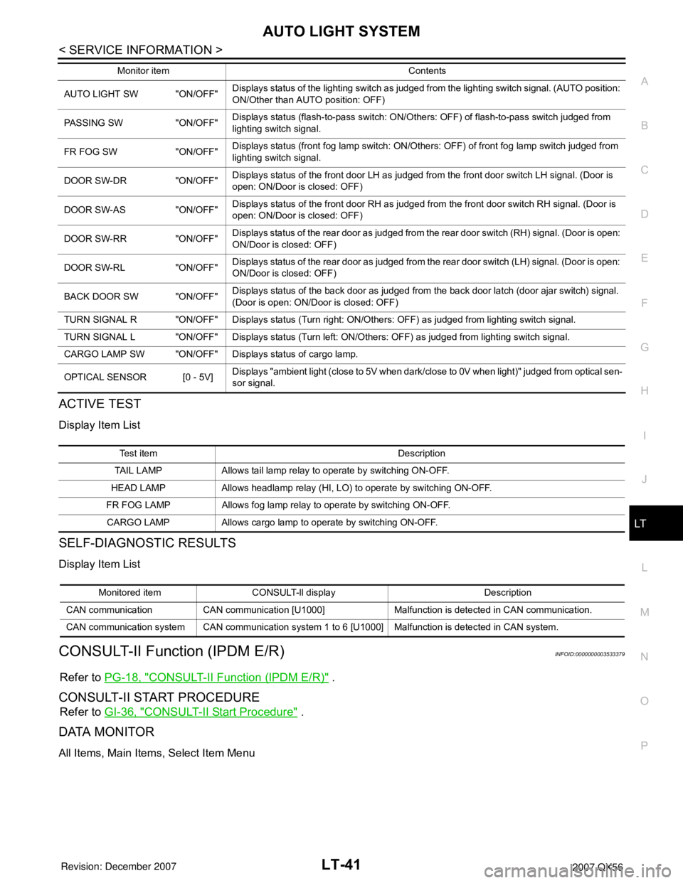
ACTIVE TEST
Display Item List
SELF-DIAGNOSTIC RESULTS
Display Item List
CONSULT-II Function (IPDM E/R)INFOID:0000000003533379
Refer to PG-18, "CONSULT-II Function (IPDM E/R)" .
CONSULT-II START PROCEDURE
Refer to GI-36, "CONSULT-II Start Procedure" .
DATA MONITOR
All Items, Main Items, Select Item Menu
AUTO LIGHT SW "ON/OFF"Displays status of the lighting switch as judged from the lighting switch signal. (AUTO position:
ON/Other than AUTO position: OFF)
PASSING SW "ON/OFF"Displays status (flash-to-pass switch: ON/Others: OFF) of flash-to-pass switch judged from
lighting switch signal.
FR FOG SW "ON/OFF"Displays status (front fog lamp switch: ON/Others: OFF) of front fog lamp switch judged from
lighting switch signal.
DOOR SW-DR "ON/OFF"Displays status of the front door LH as judged from the front door switch LH signal. (Door is
open: ON/Door is closed: OFF)
DOOR SW-AS "ON/OFF"Displays status of the front door RH as judged from the front door switch RH signal. (Door is
open: ON/Door is closed: OFF)
DOOR SW-RR "ON/OFF"Displays status of the rear door as judged from the rear door switch (RH) signal. (Door is open:
ON/Door is closed: OFF)
DOOR SW-RL "ON/OFF"Displays status of the rear door as judged from the rear door switch (LH) signal. (Door is open:
ON/Door is closed: OFF)
BACK DOOR SW "ON/OFF"Displays status of the back door as judged from the back door latch (door ajar switch) signal.
(Door is open: ON/Door is closed: OFF)
TURN SIGNAL R "ON/OFF" Displays status (Turn right: ON/Others: OFF) as judged from lighting switch signal.
TURN SIGNAL L "ON/OFF" Displays status (Turn left: ON/Others: OFF) as judged from lighting switch signal.
CARGO LAMP SW "ON/OFF" Displays status of cargo lamp.
OPTICAL SENSOR [0 - 5V] Displays "ambient light (close to 5V when dark/close to 0V when light)" judged from optical sen-
sor signal. Monitor item Contents
Te s t i t e m D e s c r i p t i o n
TAIL LAMP Allows tail lamp relay to operate by switching ON-OFF.
HEAD LAMP Allows headlamp relay (HI, LO) to operate by switching ON-OFF.
FR FOG LAMP Allows fog lamp relay to operate by switching ON-OFF.
CARGO LAMP Allows cargo lamp to operate by switching ON-OFF.
Monitored item CONSULT-ll display Description
CAN communication CAN communication [U1000] Malfunction is detected in CAN communication.
CAN communication system CAN communication system 1 to 6 [U1000] Malfunction is detected in CAN system.
Page 2249 of 3061
LT-42
< SERVICE INFORMATION >
AUTO LIGHT SYSTEM
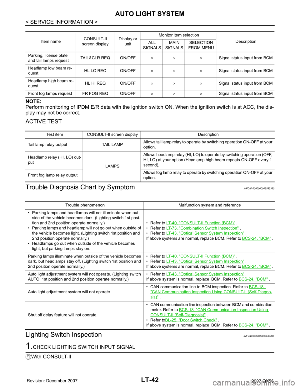
NOTE:
Perform monitoring of IPDM E/R data with the ignition switch ON. When the ignition switch is at ACC, the dis-
play may not be correct.
ACTIVE TEST
Trouble Diagnosis Chart by SymptomINFOID:0000000003533380
Lighting Switch InspectionINFOID:0000000003533381
1.CHECK LIGHTING SWITCH INPUT SIGNAL
With CONSULT-II
Item nameCONSULT-II
screen displayDisplay or
unitMonitor item selection
Description
ALL
SIGNALSMAIN
SIGNALSSELECTION
FROM MENU
Parking, license plate
and tail lamps requestTAIL&CLR REQ ON/OFF×× ×Signal status input from BCM
Headlamp low beam re-
questHL LO REQ ON/OFF×× ×Signal status input from BCM
Headlamp high beam re-
questHL HI REQ ON/OFF×× ×Signal status input from BCM
Front fog lamps request FR FOG REQ ON/OFF×× ×Signal status input from BCM
Test item CONSULT-II screen display Description
Tail lamp relay output TAIL LAMPAllows tail lamp relay to operate by switching operation ON-OFF at your
option.
Headlamp relay (HI, LO) out-
put
LAMPSAllows headlamp relay (HI, LO) to operate by switching operation (OFF,
HI, LO) at your option (Headlamp high beam repeats ON-OFF every 1
second).
Front fog lamp relay outputAllows fog lamp relay to operate by switching operation ON-OFF at your
option.
Trouble phenomenon Malfunction system and reference
• Parking lamps and headlamps will not illuminate when out-
side of the vehicle becomes dark. (Lighting switch 1st posi-
tion and 2nd position operate normally.)
• Parking lamps and headlamp will not go out when outside of
the vehicle becomes light. (Lighting switch 1st position and
2nd position operate normally.)
• Headlamps go out when outside of the vehicle becomes
light, but parking lamps stay on.•Refer to LT- 4 0 , "
CONSULT-II Function (BCM)" .
•Refer to LT- 7 3 , "
Combination Switch Inspection" .
•Refer to LT- 4 3 , "
Optical Sensor System Inspection" .
If above systems are normal, replace BCM. Refer to BCS-24, "
BCM" .
Parking lamps illuminate when outside of the vehicle becomes
dark, but headlamps stay off. (Lighting switch 1st position and
2nd position operate normally.)•Refer to LT- 4 0 , "
CONSULT-II Function (BCM)" .
•Refer to LT- 4 3 , "
Optical Sensor System Inspection" .
If above systems are normal, replace BCM. Refer to BCS-24, "
BCM" .
Auto light adjustment system will not operate. (Lighting switch
AUTO, 1st position and 2nd position operate normally.)•Refer to LT- 4 3 , "
Optical Sensor System Inspection" .
If above system is normal, replace BCM. Refer to BCS-24, "
BCM" .
Auto light adjustment system will not operate.• CAN communication line to BCM inspection. Refer to BCS-18,
"CAN Communication Inspection Using CONSULT-II (Self-Diagno-
sis)" .
Shut off delay feature will not operate.• CAN communication line inspection between BCM and combination
meter. Refer to BCS-18, "
CAN Communication Inspection Using
CONSULT-II (Self-Diagnosis)" .
•Refer toBL-25, "
Door Switch Check" .
If above system is normal, replace BCM. Refer to BCS-24, "
BCM" .
Page 2271 of 3061

LT-64
< SERVICE INFORMATION >
TURN SIGNAL AND HAZARD WARNING LAMPS
3. Perform preliminary check. Refer to LT-64, "Preliminary Check" .
4. Check symptom and repair or replace the component.
5. Do turn signal and hazard warning lamps operate normally? If YES: GO TO 6. If NO: GO TO 4.
6. Inspection End.
Preliminary CheckINFOID:0000000003533410
CHECK POWER SUPPLY AND GROUND CIRCUIT FOR BCM
Refer to BCS-15, "BCM Power Supply and Ground Circuit Inspection".
CONSULT-II Function (BCM)INFOID:0000000003533411
Refer to BCS-16, "CONSULT-II Function (BCM)".
CONSULT-II START PROCEDURE
Refer to GI-36, "CONSULT-II Start Procedure".
DATA MONITOR
Display Item List
ACTIVE TEST
Display Item List
Front Turn Signal Lamp Does Not OperateINFOID:0000000003533412
1.CHECK COMBINATION SWITCH INPUT SIGNAL
With CONSULT-II
Select "BCM" on CONSULT-II. With "FLASHER" data monitor, make
sure "TURN SIGNAL R" and "TURN SIGNAL L" turns ON-OFF
linked with operation of lighting switch.
Without CONSULT-II
Refer to LT-73, "
Combination Switch Inspection" .
OK or NG
OK >> GO TO 2.
NG >> Check lighting switch. Refer to LT-73, "
Combination Switch Inspection".
2.ACTIVE TEST
With CONSULT-II
Monitor item Contents
IGN ON SW "ON/OFF" Displays "IGN position (ON)/OFF, ACC position (OFF)" judged from the ignition switch signal.
HAZARD SW "ON/OFF" Displays "Hazard ON (ON)/Hazard OFF (OFF)" status, determined from hazard switch signal.
TURN SIGNAL R "ON/OFF" Displays "Turn right (ON)/Other (OFF)" status, determined from lighting switch signal.
TURN SIGNAL L "ON/OFF" Displays "Turn left (ON)/Other (OFF)" status, determined from lighting switch signal.
BRAKE SW "ON/OFF" Displays status of stop lamp switch.
Test item Description
FLASHER (RH) Turn signal lamp (right) can be operated by any ON-OFF operations.
FLASHER (LH) Turn signal lamp (left) can be operated by any ON-OFF operations.
When lighting switch is in
TURN RH position: TURN SIGNAL R ON
When lighting switch is in
TURN LH position: TURN SIGNAL L ON
SKIA4499E
Page 2280 of 3061
COMBINATION SWITCH
LT-73
< SERVICE INFORMATION >
C
D
E
F
G
H
I
J
L
MA
B
LT
N
O
P
CONSULT-II Function (BCM)INFOID:0000000003533423
Refer to BCS-16, "CONSULT-II Function (BCM)" .
CONSULT-II START PROCEDURE
Refer to GI-36, "CONSULT-II Start Procedure" .
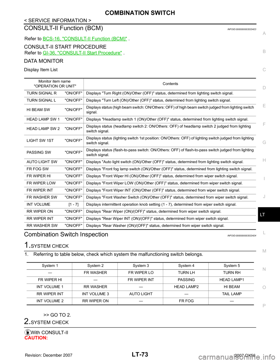
DATA MONITOR
Display Item List
Combination Switch InspectionINFOID:0000000003533424
1.SYSTEM CHECK
1. Referring to table below, check which system the malfunctioning switch belongs.
>> GO TO 2.
2.SYSTEM CHECK
With CONSULT-II
CAUTION:
Monitor item name
"OPERATION OR UNIT"Contents
TURN SIGNAL R "ON/OFF" Displays "Turn Right (ON)/Other (OFF)" status, determined from lighting switch signal.
TURN SIGNAL L "ON/OFF" Displays "Turn Left (ON)/Other (OFF)" status, determined from lighting switch signal.
HI BEAM SW "ON/OFF"Displays status (high beam switch: ON/Others: OFF) of high beam switch judged from lighting switch
signal.
HEAD LAMP SW 1 "ON/OFF" Displays "Headlamp switch 1 (ON)/Other (OFF)" status, determined from lighting switch signal.
HEAD LAMP SW 2 "ON/OFF"Displays status (headlamp switch 2: ON/Others: OFF) of headlamp switch 2 judged from lighting
switch signal.
LIGHT SW 1ST "ON/OFF"Displays status (lighting switch 1st position: ON/Others: OFF) of lighting switch judged from lighting
switch signal.
PASSING SW "ON/OFF"Displays status (flash-to-pass switch: ON/Others: OFF) of flash-to-pass switch judged from lighting
switch signal.
AUTO LIGHT SW "ON/OFF" Displays "Auto light switch (ON)/Other (OFF)" status, determined from lighting switch signal.
FR FOG SW "ON/OFF" Displays "Front fog lamp switch (ON)/Other (OFF)" status, determined from lighting switch signal.
FR WIPER HI "ON/OFF" Displays "Front Wiper HI (ON)/Other (OFF)" status, determined from wiper switch signal.
FR WIPER LOW "ON/OFF" Displays "Front Wiper LOW (ON)/Other (OFF)" status, determined from wiper switch signal.
FR WIPER INT "ON/OFF" Displays "Front Wiper INT (ON)/Other (OFF)" status, determined from wiper switch signal.
FR WASHER SW "ON/OFF" Displays "Front Washer Switch (ON)/Other (OFF)" status, determined from wiper switch signal.
INT VOLUME [1 - 7] Displays intermittent operation knob setting (1 - 7), determined from wiper switch signal.
RR WIPER ON "ON/OFF" Displays "Rear Wiper (ON)/(OFF)" status, determined from wiper switch signal.
RR WIPER INT "ON/OFF" Displays "Rear Wiper INT (ON)/(OFF)" status, determined from wiper switch signal.
RR WASHER SW "ON/OFF" Displays "Rear Washer (ON)/(OFF)" status, determined from wiper switch signal.
System 1 System 2 System 3 System 4 System 5
— FR WASHER FR WIPER LO TURN LH TURN RH
FR WIPER HI — FR WIPER INT PASSING HEAD LAMP1
INT VOLUME 1 RR WASHER — HEAD LAMP2 HI BEAM
RR WIPER INT INT VOLUME 3 AUTO LIGHT — TAIL LAMP
INT VOLUME 2 RR WIPER ON — FR FOG —
Page 2321 of 3061
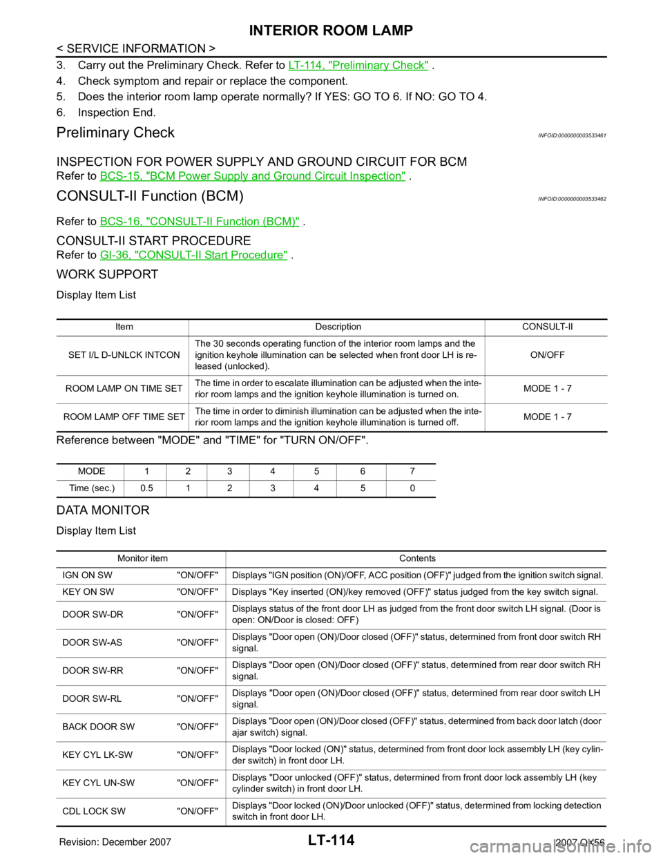
LT-114
< SERVICE INFORMATION >
INTERIOR ROOM LAMP
3. Carry out the Preliminary Check. Refer to LT-114, "Preliminary Check" .
4. Check symptom and repair or replace the component.
5. Does the interior room lamp operate normally? If YES: GO TO 6. If NO: GO TO 4.
6. Inspection End.
Preliminary CheckINFOID:0000000003533461
INSPECTION FOR POWER SUPPLY AND GROUND CIRCUIT FOR BCM
Refer to BCS-15, "BCM Power Supply and Ground Circuit Inspection" .
CONSULT-II Function (BCM)INFOID:0000000003533462
Refer to BCS-16, "CONSULT-II Function (BCM)" .
CONSULT-II START PROCEDURE
Refer to GI-36, "CONSULT-II Start Procedure" .
WORK SUPPORT
Display Item List
Reference between "MODE" and "TIME" for "TURN ON/OFF".
DATA MONITOR
Display Item List
Item Description CONSULT-II
SET I/L D-UNLCK INTCONThe 30 seconds operating function of the interior room lamps and the
ignition keyhole illumination can be selected when front door LH is re-
leased (unlocked). ON/OFF
ROOM LAMP ON TIME SETThe time in order to escalate illumination can be adjusted when the inte-
rior room lamps and the ignition keyhole illumination is turned on.MODE 1 - 7
ROOM LAMP OFF TIME SETThe time in order to diminish illumination can be adjusted when the inte-
rior room lamps and the ignition keyhole illumination is turned off.MODE 1 - 7
MODE 123 4 5 6 7
Time (sec.) 0.5 1 2 3 4 5 0
Monitor item Contents
IGN ON SW "ON/OFF" Displays "IGN position (ON)/OFF, ACC position (OFF)" judged from the ignition switch signal.
KEY ON SW "ON/OFF" Displays "Key inserted (ON)/key removed (OFF)" status judged from the key switch signal.
DOOR SW-DR "ON/OFF"Displays status of the front door LH as judged from the front door switch LH signal. (Door is
open: ON/Door is closed: OFF)
DOOR SW-AS "ON/OFF"Displays "Door open (ON)/Door closed (OFF)" status, determined from front door switch RH
signal.
DOOR SW-RR "ON/OFF"Displays "Door open (ON)/Door closed (OFF)" status, determined from rear door switch RH
signal.
DOOR SW-RL "ON/OFF"Displays "Door open (ON)/Door closed (OFF)" status, determined from rear door switch LH
signal.
BACK DOOR SW "ON/OFF"Displays "Door open (ON)/Door closed (OFF)" status, determined from back door latch (door
ajar switch) signal.
KEY CYL LK-SW "ON/OFF"Displays "Door locked (ON)" status, determined from front door lock assembly LH (key cylin-
der switch) in front door LH.
KEY CYL UN-SW "ON/OFF"Displays "Door unlocked (OFF)" status, determined from front door lock assembly LH (key
cylinder switch) in front door LH.
CDL LOCK SW "ON/OFF"Displays "Door locked (ON)/Door unlocked (OFF)" status, determined from locking detection
switch in front door LH.
Page 2322 of 3061
INTERIOR ROOM LAMP
LT-115
< SERVICE INFORMATION >
C
D
E
F
G
H
I
J
L
MA
B
LT
N
O
P
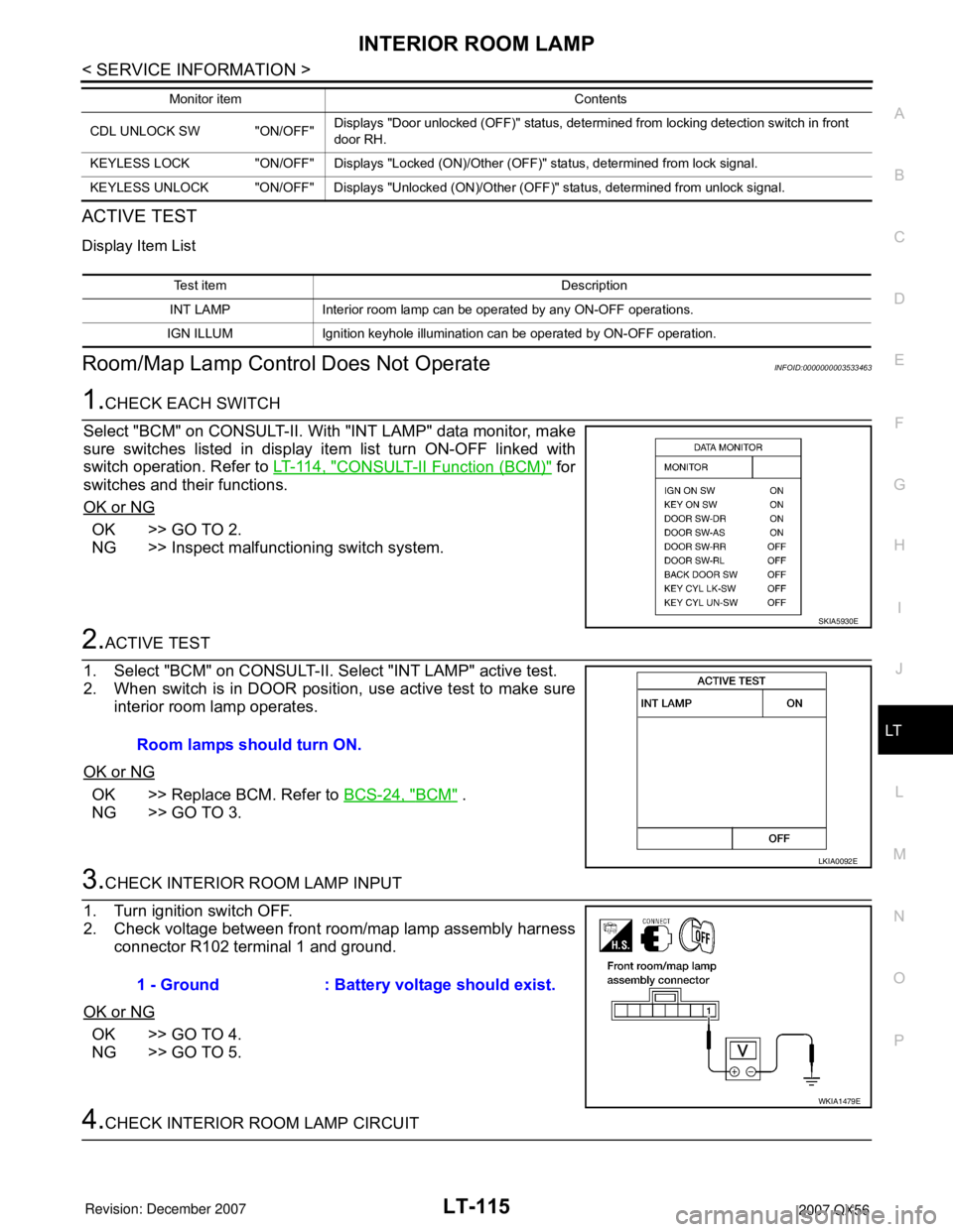
ACTIVE TEST
Display Item List
Room/Map Lamp Control Does Not OperateINFOID:0000000003533463
1.CHECK EACH SWITCH
Select "BCM" on CONSULT-II. With "INT LAMP" data monitor, make
sure switches listed in display item list turn ON-OFF linked with
switch operation. Refer to LT-114, "
CONSULT-II Function (BCM)" for
switches and their functions.
OK or NG
OK >> GO TO 2.
NG >> Inspect malfunctioning switch system.
2.ACTIVE TEST
1. Select "BCM" on CONSULT-II. Select "INT LAMP" active test.
2. When switch is in DOOR position, use active test to make sure
interior room lamp operates.
OK or NG
OK >> Replace BCM. Refer to BCS-24, "BCM" .
NG >> GO TO 3.
3.CHECK INTERIOR ROOM LAMP INPUT
1. Turn ignition switch OFF.
2. Check voltage between front room/map lamp assembly harness
connector R102 terminal 1 and ground.
OK or NG
OK >> GO TO 4.
NG >> GO TO 5.
4.CHECK INTERIOR ROOM LAMP CIRCUIT
CDL UNLOCK SW "ON/OFF"Displays "Door unlocked (OFF)" status, determined from locking detection switch in front
door RH.
KEYLESS LOCK "ON/OFF" Displays "Locked (ON)/Other (OFF)" status, determined from lock signal.
KEYLESS UNLOCK "ON/OFF" Displays "Unlocked (ON)/Other (OFF)" status, determined from unlock signal.Monitor item Contents
Test item Description
INT LAMP Interior room lamp can be operated by any ON-OFF operations.
IGN ILLUM Ignition keyhole illumination can be operated by ON-OFF operation.
SKIA5930E
Room lamps should turn ON.
LKIA0092E
1 - Ground : Battery voltage should exist.
WKIA1479E