2007 INFINITI QX56 display
[x] Cancel search: displayPage 2429 of 3061
IPDM E/R (INTELLIGENT POWER DISTRIBUTION MODULE ENGINE ROOM)
PG-27
< SERVICE INFORMATION >
C
D
E
F
G
H
I
J
L
MA
B
PG
N
O
P
OK or NG
OK >> GO TO 2.
NG >> Replace fuse or fusible link.
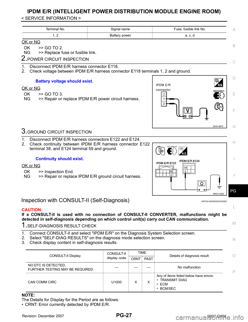
2.POWER CIRCUIT INSPECTION
1. Disconnect IPDM E/R harness connector E118.
2. Check voltage between IPDM E/R harness connector E118 terminals 1, 2 and ground.
OK or NG
OK >> GO TO 3.
NG >> Repair or replace IPDM E/R power circuit harness.
3.GROUND CIRCUIT INSPECTION
1. Disconnect IPDM E/R harness connectors E122 and E124.
2. Check continuity between IPDM E/R harness connector E122
terminal 38, and E124 terminal 59 and ground.
OK or NG
OK >> Inspection End.
NG >> Repair or replace IPDM E/R ground circuit harness.
Inspection with CONSULT-II (Self-Diagnosis)INFOID:0000000003533843
CAUTION:
If a CONSULT-II is used with no connection of CONSULT-II CONVERTER, malfunctions might be
detected in self-diagnosis depending on which control unit(s) carry out CAN communication.
1.SELF-DIAGNOSIS RESULT CHECK
1. Connect CONSULT-II and select "IPDM E/R" on the Diagnosis System Selection screen.
2. Select "SELF-DIAG RESULTS" on the diagnosis mode selection screen.
3. Check display content in self-diagnosis results.
NOTE:
The Details for Display for the Period are as follows:
• CRNT: Error currently detected by IPDM E/R.
Terminal No. Signal name Fuse, fusible link No.
1, 2 Battery power a, c, d
Battery voltage should exist.
SKIA1987E
Continuity should exist.
WKIA1453E
CONSULT-II DisplayCONSULT-II
display codeTIME
Details of diagnosis result
CRNT PAST
NO DTC IS DETECTED.
FURTHER TESTING MAY BE REQUIRED.——— No malfunction
CAN COMM CIRC U1000 X XAny of items listed below have errors:
• TRANSMIT DIAG
•ECM
• BCM/SEC
Page 2430 of 3061
PG-28
< SERVICE INFORMATION >
IPDM E/R (INTELLIGENT POWER DISTRIBUTION MODULE ENGINE ROOM)
• PAST: Error detected in the past and stored in IPDM E/R memory.
Contents displayed
NO DTC DETECTED. FURTHER TESTING MAY BE REQUIRED.>>Inspection End.
CAN COMM CIRC>>Print out the self-diagnosis result and refer to LAN-40
.
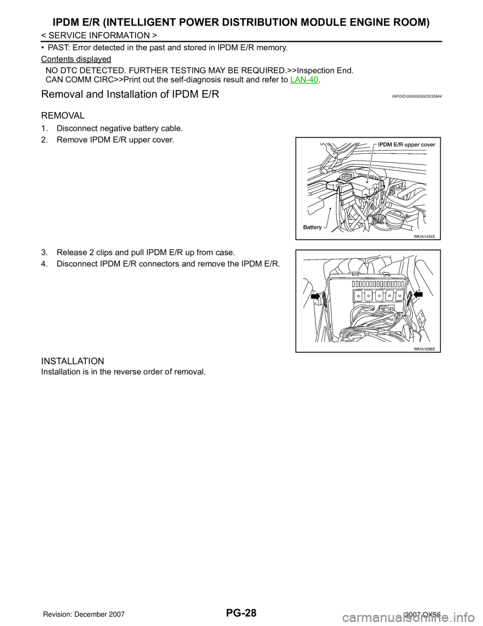
Removal and Installation of IPDM E/RINFOID:0000000003533844
REMOVAL
1. Disconnect negative battery cable.
2. Remove IPDM E/R upper cover.
3. Release 2 clips and pull IPDM E/R up from case.
4. Disconnect IPDM E/R connectors and remove the IPDM E/R.
INSTALLATION
Installation is in the reverse order of removal.
WKIA1454E
WKIA1696E
Page 2546 of 3061
RF-14
< SERVICE INFORMATION >
SUNROOF
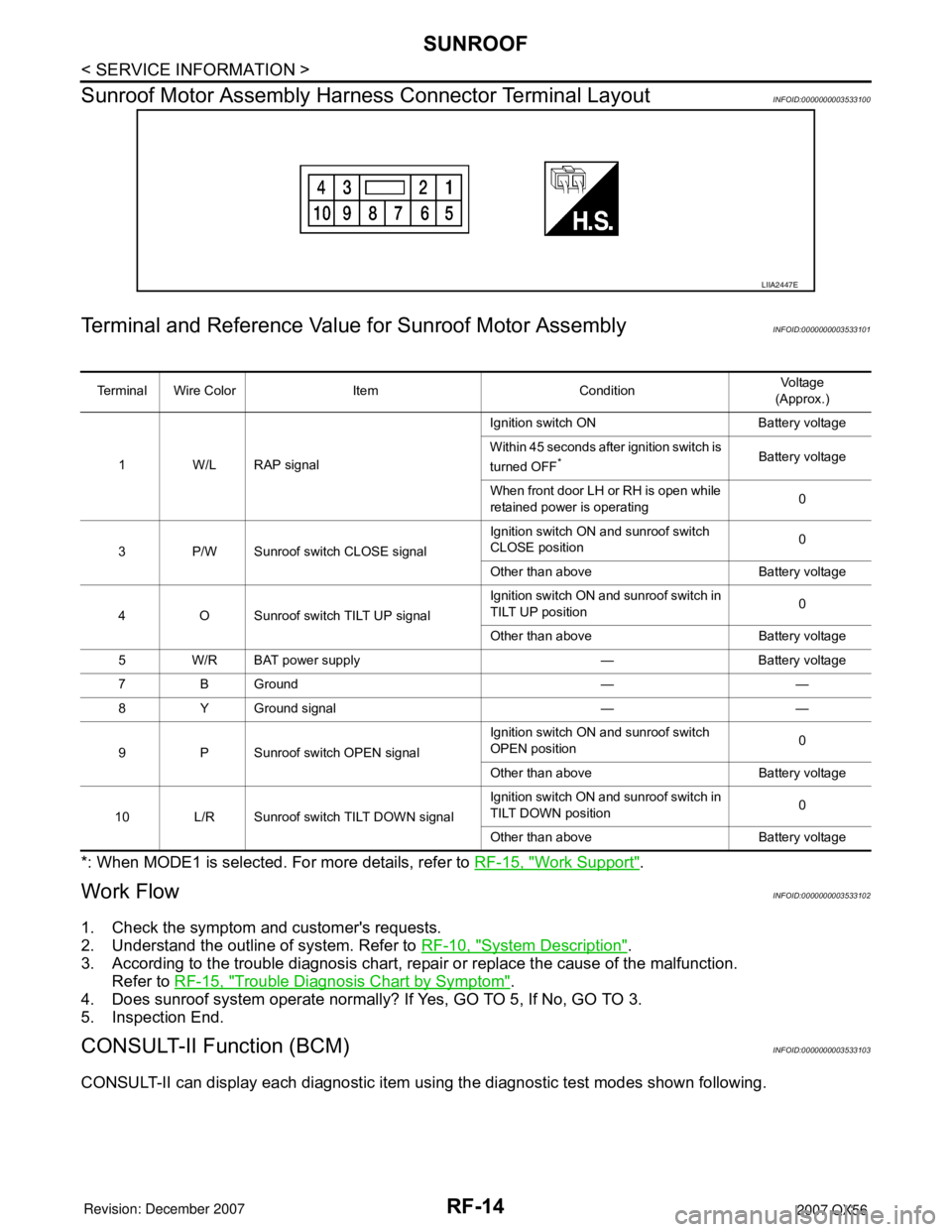
Sunroof Motor Assembly Harness Connector Terminal Layout
INFOID:0000000003533100
Terminal and Reference Value for Sunroof Motor AssemblyINFOID:0000000003533101
*: When MODE1 is selected. For more details, refer to RF-15, "Work Support".
Work FlowINFOID:0000000003533102
1. Check the symptom and customer's requests.
2. Understand the outline of system. Refer to RF-10, "
System Description".
3. According to the trouble diagnosis chart, repair or replace the cause of the malfunction.
Refer to RF-15, "
Trouble Diagnosis Chart by Symptom".
4. Does sunroof system operate normally? If Yes, GO TO 5, If No, GO TO 3.
5. Inspection End.
CONSULT-II Function (BCM)INFOID:0000000003533103
CONSULT-II can display each diagnostic item using the diagnostic test modes shown following.
LIIA2447E
Terminal Wire Color Item ConditionVol tag e
(Approx.)
1 W/L RAP signalIgnition switch ON Battery voltage
Within 45 seconds after ignition switch is
turned OFF
*Battery voltage
When front door LH or RH is open while
retained power is operating0
3 P/W Sunroof switch CLOSE signalIgnition switch ON and sunroof switch
CLOSE position0
Other than above Battery voltage
4 O Sunroof switch TILT UP signalIgnition switch ON and sunroof switch in
TILT UP position0
Other than above Battery voltage
5 W/R BAT power supply — Battery voltage
7 B Ground — —
8 Y Ground signal — —
9 P Sunroof switch OPEN signalIgnition switch ON and sunroof switch
OPEN position0
Other than above Battery voltage
10 L/R Sunroof switch TILT DOWN signalIgnition switch ON and sunroof switch in
TILT DOWN position0
Other than above Battery voltage
Page 2547 of 3061
SUNROOF
RF-15
< SERVICE INFORMATION >
C
D
E
F
G
H
J
K
L
MA
B
RF
N
O
P
CONSULT-II START PROCEDURE
Refer to GI-36, "CONSULT-II Start Procedure".
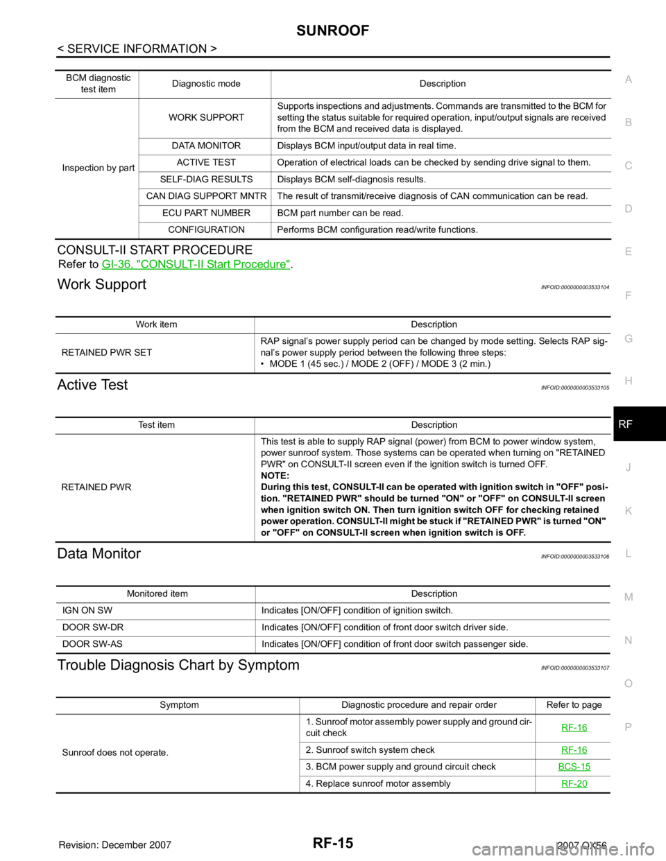
Work SupportINFOID:0000000003533104
Active TestINFOID:0000000003533105
Data MonitorINFOID:0000000003533106
Trouble Diagnosis Chart by SymptomINFOID:0000000003533107
BCM diagnostic
test itemDiagnostic mode Description
Inspection by partWORK SUPPORTSupports inspections and adjustments. Commands are transmitted to the BCM for
setting the status suitable for required operation, input/output signals are received
from the BCM and received data is displayed.
DATA MONITOR Displays BCM input/output data in real time.
ACTIVE TEST Operation of electrical loads can be checked by sending drive signal to them.
SELF-DIAG RESULTS Displays BCM self-diagnosis results.
CAN DIAG SUPPORT MNTR The result of transmit/receive diagnosis of CAN communication can be read.
ECU PART NUMBER BCM part number can be read.
CONFIGURATION Performs BCM configuration read/write functions.
Work item Description
RETAINED PWR SETRAP signal’s power supply period can be changed by mode setting. Selects RAP sig-
nal’s power supply period between the following three steps:
• MODE 1 (45 sec.) / MODE 2 (OFF) / MODE 3 (2 min.)
Test item Description
RETAINED PWRThis test is able to supply RAP signal (power) from BCM to power window system,
power sunroof system. Those systems can be operated when turning on "RETAINED
PWR" on CONSULT-II screen even if the ignition switch is turned OFF.
NOTE:
During this test, CONSULT-II can be operated with ignition switch in "OFF" posi-
tion. "RETAINED PWR" should be turned "ON" or "OFF" on CONSULT-II screen
when ignition switch ON. Then turn ignition switch OFF for checking retained
power operation. CONSULT-II might be stuck if "RETAINED PWR" is turned "ON"
or "OFF" on CONSULT-II screen when ignition switch is OFF.
Monitored item Description
IGN ON SW Indicates [ON/OFF] condition of ignition switch.
DOOR SW-DR Indicates [ON/OFF] condition of front door switch driver side.
DOOR SW-AS Indicates [ON/OFF] condition of front door switch passenger side.
Symptom Diagnostic procedure and repair order Refer to page
Sunroof does not operate.1. Sunroof motor assembly power supply and ground cir-
cuit checkRF-16
2. Sunroof switch system checkRF-16
3. BCM power supply and ground circuit checkBCS-15
4. Replace sunroof motor assemblyRF-20
Page 2601 of 3061
TROUBLE DIAGNOSIS
RSU-11
< SERVICE INFORMATION >
C
D
F
G
H
I
J
K
L
MA
B
RSU
N
O
P
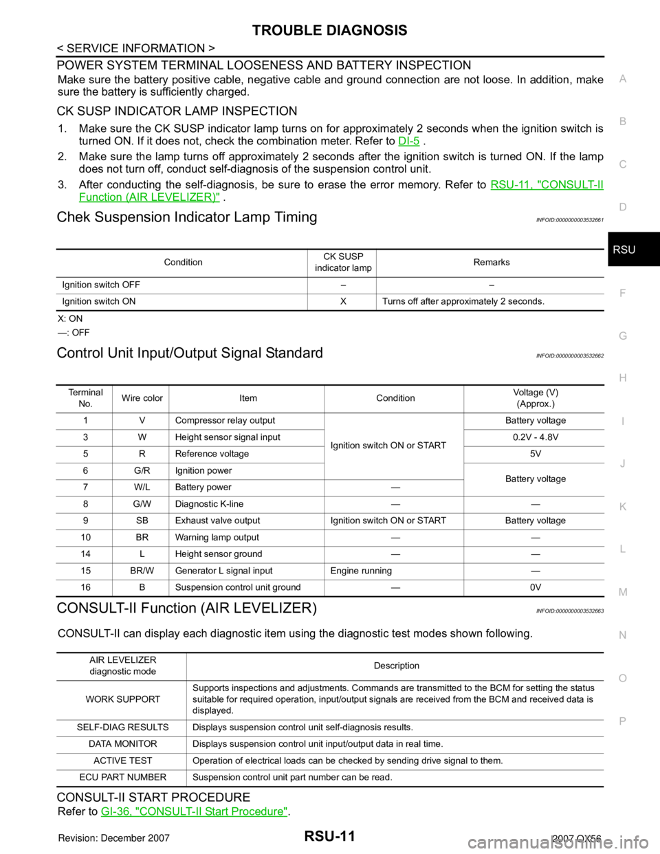
POWER SYSTEM TERMINAL LOOSENESS AND BATTERY INSPECTION
Make sure the battery positive cable, negative cable and ground connection are not loose. In addition, make
sure the battery is sufficiently charged.
CK SUSP INDICATOR LAMP INSPECTION
1. Make sure the CK SUSP indicator lamp turns on for approximately 2 seconds when the ignition switch is
turned ON. If it does not, check the combination meter. Refer to DI-5
.
2. Make sure the lamp turns off approximately 2 seconds after the ignition switch is turned ON. If the lamp
does not turn off, conduct self-diagnosis of the suspension control unit.
3. After conducting the self-diagnosis, be sure to erase the error memory. Refer to RSU-11, "
CONSULT-II
Function (AIR LEVELIZER)" .
Chek Suspension Indicator Lamp TimingINFOID:0000000003532661
X: ON
—: OFF
Control Unit Input/Output Signal StandardINFOID:0000000003532662
CONSULT-II Function (AIR LEVELIZER)INFOID:0000000003532663
CONSULT-II can display each diagnostic item using the diagnostic test modes shown following.
CONSULT-II START PROCEDURE
Refer to GI-36, "CONSULT-II Start Procedure".
ConditionCK SUSP
indicator lampRemarks
Ignition switch OFF – –
Ignition switch ON X Turns off after approximately 2 seconds.
Te r m i n a l
No.Wire color Item ConditionVoltage (V)
(Approx.)
1 V Compressor relay output
Ignition switch ON or STARTBattery voltage
3 W Height sensor signal input 0.2V - 4.8V
5 R Reference voltage 5V
6 G/R Ignition power
Battery voltage
7W/LBattery power —
8 G/W Diagnostic K-line — —
9 SB Exhaust valve output Ignition switch ON or START Battery voltage
10 BR Warning lamp output — —
14 L Height sensor ground — —
15 BR/W Generator L signal input Engine running —
16 B Suspension control unit ground — 0V
AIR LEVELIZER
diagnostic modeDescription
WORK SUPPORTSupports inspections and adjustments. Commands are transmitted to the BCM for setting the status
suitable for required operation, input/output signals are received from the BCM and received data is
displayed.
SELF-DIAG RESULTS Displays suspension control unit self-diagnosis results.
DATA MONITOR Displays suspension control unit input/output data in real time.
ACTIVE TEST Operation of electrical loads can be checked by sending drive signal to them.
ECU PART NUMBER Suspension control unit part number can be read.
Page 2602 of 3061
RSU-12
< SERVICE INFORMATION >
TROUBLE DIAGNOSIS
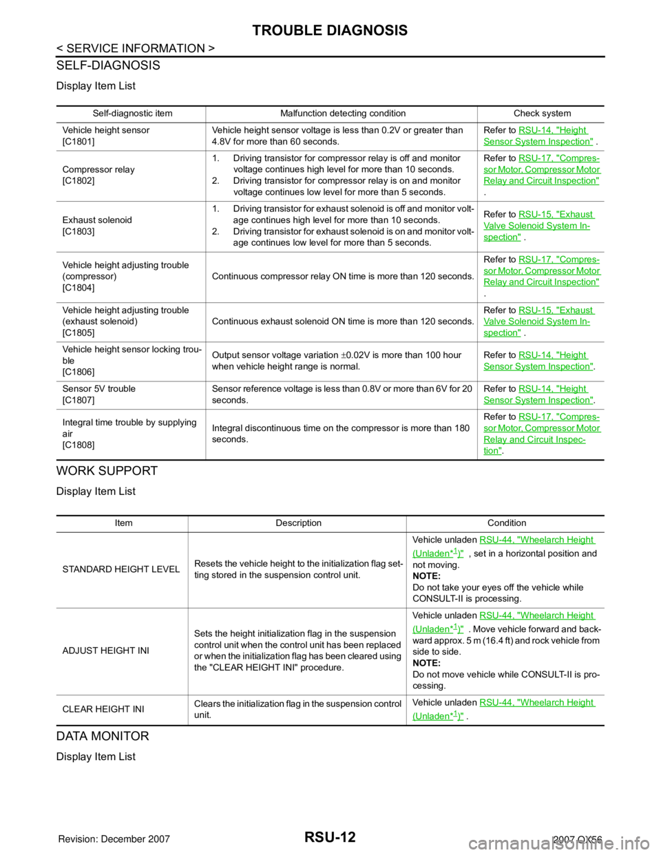
SELF-DIAGNOSIS
Display Item List
WORK SUPPORT
Display Item List
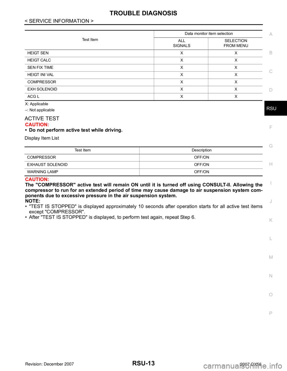
DATA MONITOR
Display Item List
Self-diagnostic item Malfunction detecting condition Check system
Vehicle height sensor
[C1801]Vehicle height sensor voltage is less than 0.2V or greater than
4.8V for more than 60 seconds.Refer to RSU-14, "
Height
Sensor System Inspection" .
Compressor relay
[C1802]1. Driving transistor for compressor relay is off and monitor
voltage continues high level for more than 10 seconds.
2. Driving transistor for compressor relay is on and monitor
voltage continues low level for more than 5 seconds.Refer to RSU-17, "
Compres-
sor Motor, Compressor Motor
Relay and Circuit Inspection"
.
Exhaust solenoid
[C1803]1. Driving transistor for exhaust solenoid is off and monitor volt-
age continues high level for more than 10 seconds.
2. Driving transistor for exhaust solenoid is on and monitor volt-
age continues low level for more than 5 seconds.Refer to RSU-15, "
Exhaust
Valve Solenoid System In-
spection" .
Vehicle height adjusting trouble
(compressor)
[C1804]Continuous compressor relay ON time is more than 120 seconds.Refer to RSU-17, "
Compres-
sor Motor, Compressor Motor
Relay and Circuit Inspection"
.
Vehicle height adjusting trouble
(exhaust solenoid)
[C1805]Continuous exhaust solenoid ON time is more than 120 seconds.Refer to RSU-15, "
Exhaust
Valve Solenoid System In-
spection" .
Vehicle height sensor locking trou-
ble
[C1806]Output sensor voltage variation ±0.02V is more than 100 hour
when vehicle height range is normal.Refer to RSU-14, "
Height
Sensor System Inspection".
Sensor 5V trouble
[C1807]Sensor reference voltage is less than 0.8V or more than 6V for 20
seconds.Refer to RSU-14, "
Height
Sensor System Inspection".
Integral time trouble by supplying
air
[C1808]Integral discontinuous time on the compressor is more than 180
seconds.Refer to RSU-17, "
Compres-
sor Motor, Compressor Motor
Relay and Circuit Inspec-
tion".
Item Description Condition
STANDARD HEIGHT LEVELResets the vehicle height to the initialization flag set-
ting stored in the suspension control unit.Vehicle unladen RSU-44, "
Wheelarch Height
(Unladen*1)" , set in a horizontal position and
not moving.
NOTE:
Do not take your eyes off the vehicle while
CONSULT-II is processing.
ADJUST HEIGHT INISets the height initialization flag in the suspension
control unit when the control unit has been replaced
or when the initialization flag has been cleared using
the "CLEAR HEIGHT INI" procedure.Vehicle unladen RSU-44, "
Wheelarch Height
(Unladen*1)" . Move vehicle forward and back-
ward approx. 5 m (16.4 ft) and rock vehicle from
side to side.
NOTE:
Do not move vehicle while CONSULT-II is pro-
cessing.
CLEAR HEIGHT INIClears the initialization flag in the suspension control
unit.Vehicle unladen RSU-44, "
Wheelarch Height
(Unladen*1)" .
Page 2603 of 3061
TROUBLE DIAGNOSIS
RSU-13
< SERVICE INFORMATION >
C
D
F
G
H
I
J
K
L
MA
B
RSU
N
O
P
X: Applicable
–: Not applicable
ACTIVE TEST
CAUTION:
• Do not perform active test while driving.
Display Item List
CAUTION:
The "COMPRESSOR" active test will remain ON until it is turned off using CONSULT-II. Allowing the
compressor to run for an extended period of time may cause damage to air suspension system com-
ponents due to excessive pressure in the air suspension system.
NOTE:
• "TEST IS STOPPED" is displayed approximately 10 seconds after operation starts for all active test items
except "COMPRESSOR".
• After "TEST IS STOPPED" is displayed, to perform test again, repeat Step 6.
Test ItemData monitor item selection
ALL
SIGNALSSELECTION
FROM MENU
HEIGT SENXX
HEIGT CALCXX
SEN FIX TIME X X
HEIGT INI VAL X X
COMPRESSOR X X
EXH SOLENOID X X
ACG LXX
Test Item Description
COMPRESSOROFF/ON
EXHAUST SOLENOID OFF/ON
WARNING LAMPOFF/ON
Page 2604 of 3061
RSU-14
< SERVICE INFORMATION >
TROUBLE DIAGNOSIS FOR SELF-DIAGNOSTIC ITEMS
TROUBLE DIAGNOSIS FOR SELF-DIAGNOSTIC ITEMS
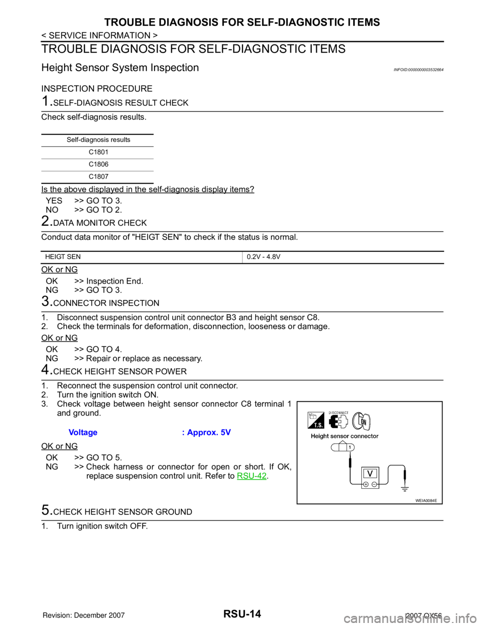
Height Sensor System InspectionINFOID:0000000003532664
INSPECTION PROCEDURE
1.SELF-DIAGNOSIS RESULT CHECK
Check self-diagnosis results.
Is the above displayed in the self-diagnosis display items?
YES >> GO TO 3.
NO >> GO TO 2.
2.DATA MONITOR CHECK
Conduct data monitor of "HEIGT SEN" to check if the status is normal.
OK or NG
OK >> Inspection End.
NG >> GO TO 3.
3.CONNECTOR INSPECTION
1. Disconnect suspension control unit connector B3 and height sensor C8.
2. Check the terminals for deformation, disconnection, looseness or damage.
OK or NG
OK >> GO TO 4.
NG >> Repair or replace as necessary.
4.CHECK HEIGHT SENSOR POWER
1. Reconnect the suspension control unit connector.
2. Turn the ignition switch ON.
3. Check voltage between height sensor connector C8 terminal 1
and ground.
OK or NG
OK >> GO TO 5.
NG >> Check harness or connector for open or short. If OK,
replace suspension control unit. Refer to RSU-42
.
5.CHECK HEIGHT SENSOR GROUND
1. Turn ignition switch OFF.
Self-diagnosis results
C1801
C1806
C1807
HEIGT SEN 0.2V - 4.8V
Voltage : Approx. 5V
WEIA0084E